


Results 301 to 320 of 573
-
05-14-2013 #301

 Registered User
- Join Date
- Jan 2011
- Location
- Boston, MA
- Posts
- 1,180

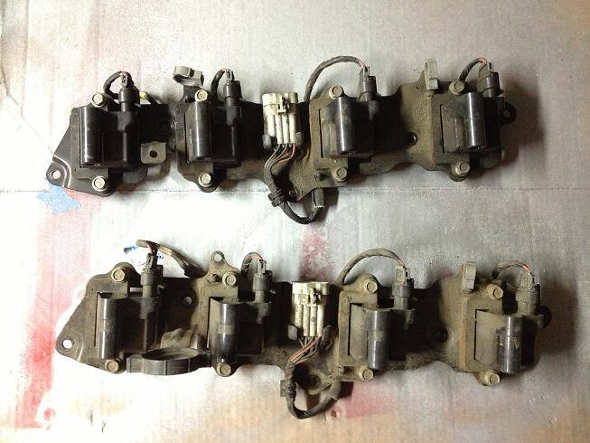
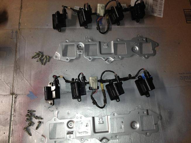
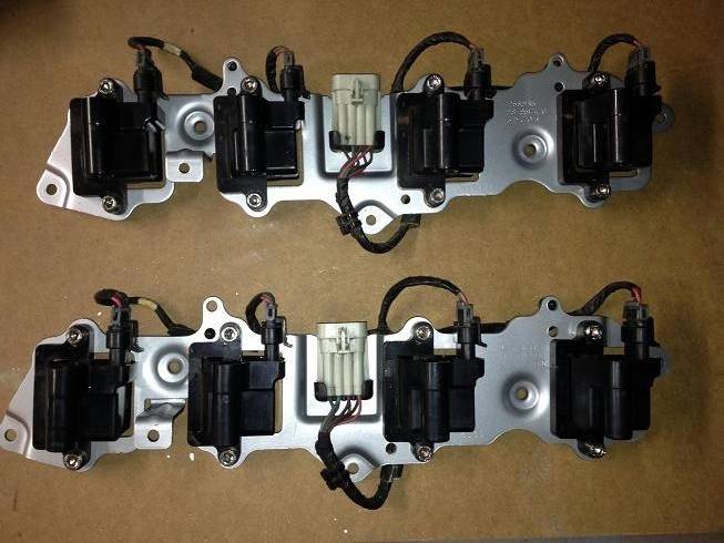
I think I mentioned that I was cleaning up my coil packs and re-painting the bracket a while back, so here are some pics. I cleaned the coils with a dry nylon brush, then went back with a damp towel, and a final cleaning with a cloth with brake cleaner on it. Then I cleaned up the brackets, cleaned them with brake cleaner and then prep spray and hit them with a coat of primer and a couple coats of aluminum colored paint to match the valve covers. I added some new hex head bolts (I'm using them in several locations on the engine), and reassembled them. Eventually I'll hide the coils, but this will do for now.
Before:
Cleaned and Painted:
Re-assembled:
-
05-17-2013 #302
Registered User
- Join Date
- Jul 2005
- Location
- Grain Valley, MO
- Posts
- 92
I have to say thanks to you for all the info you have poured in to this thread. I begin the swap on my 68 Camaro in 2 weeks and you have really helped me nail down some of the details.
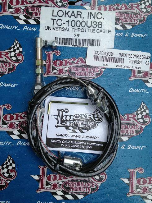
One question though, what cable do you plan on using with the new gas pedal?
-
05-18-2013 #303
Registered User
- Join Date
- Jan 2011
- Location
- Boston, MA
- Posts
- 1,180
Good luck with your swap. I'll keep the pics coming. Originally Posted by Mizzouri

I'm using the Lokar cable, I may try to get to it tomorrow:
-
05-18-2013 #304
Registered User
- Join Date
- Jan 2011
- Location
- Boston, MA
- Posts
- 1,180
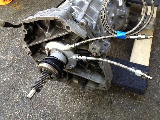
Both fittings arrived for my slave cylinder. I ended up going with the Russell fitting direct to the slave and then -4AN hose to a -4AN union.
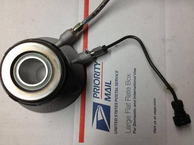
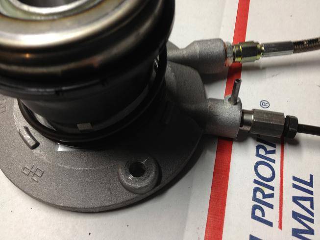
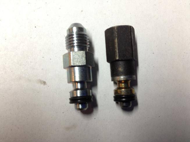
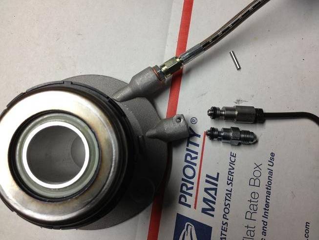
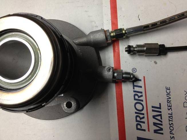
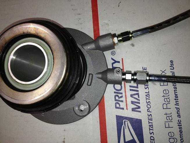
Tick Performance Speed Bleeder on top, and -4AN connection on bottom:
-
05-18-2013 #305
Registered User
- Join Date
- Jan 2011
- Location
- Boston, MA
- Posts
- 1,180
Which meant it was finally time. I'll let the pics do the talking for once...
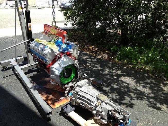
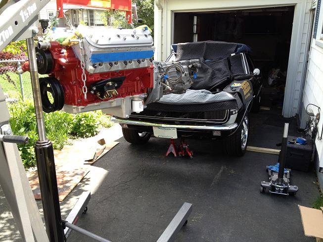
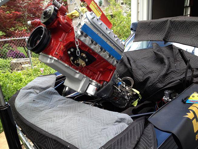
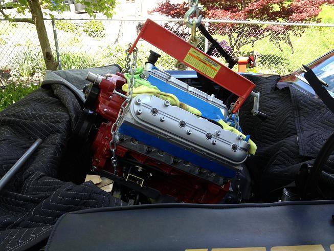
eBay headers needed a little convincing. When these things rust out, I'll buy some decent headers. They hit in three places.:sad:
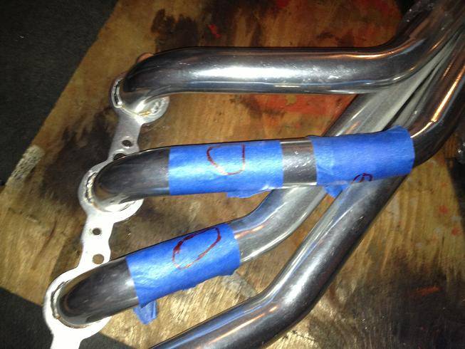
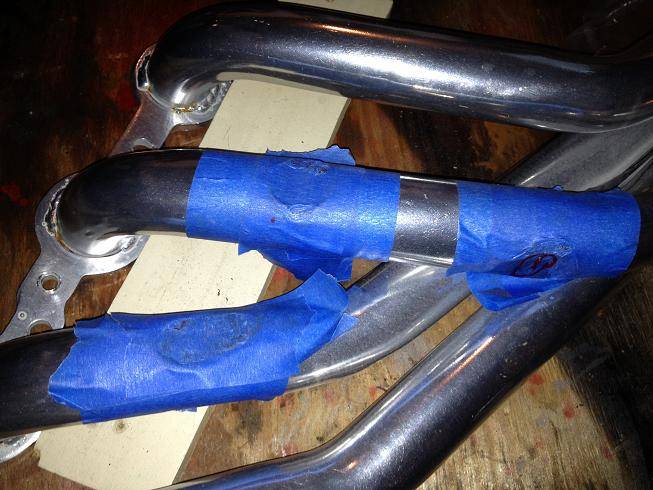
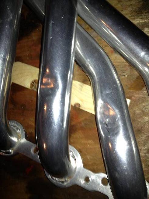
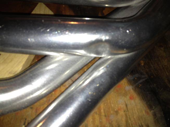
Like a glove:
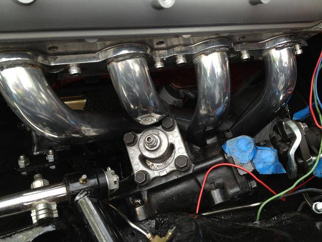
And finally...
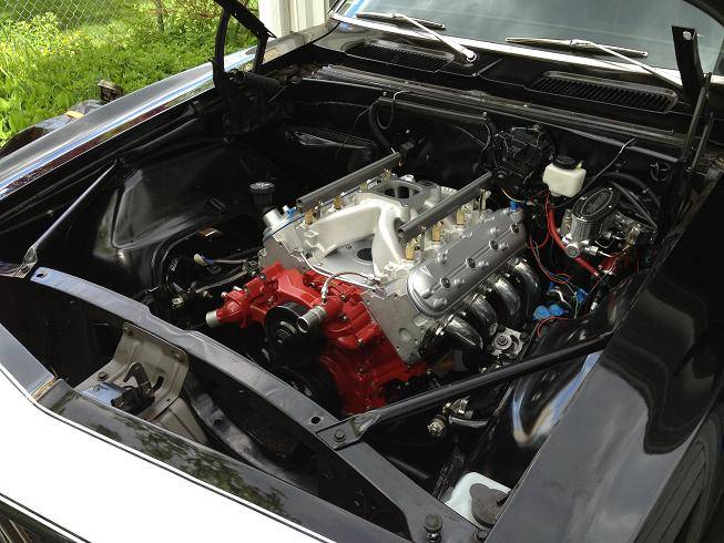
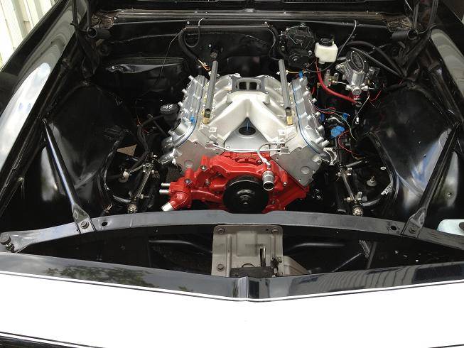
-
05-18-2013 #306
Registered User
- Join Date
- Sep 2012
- Posts
- 108
beatiful!!!
-
05-20-2013 #307
Registered User
- Join Date
- Jan 2011
- Location
- Boston, MA
- Posts
- 1,180
Thanks! Originally Posted by The Am1nal
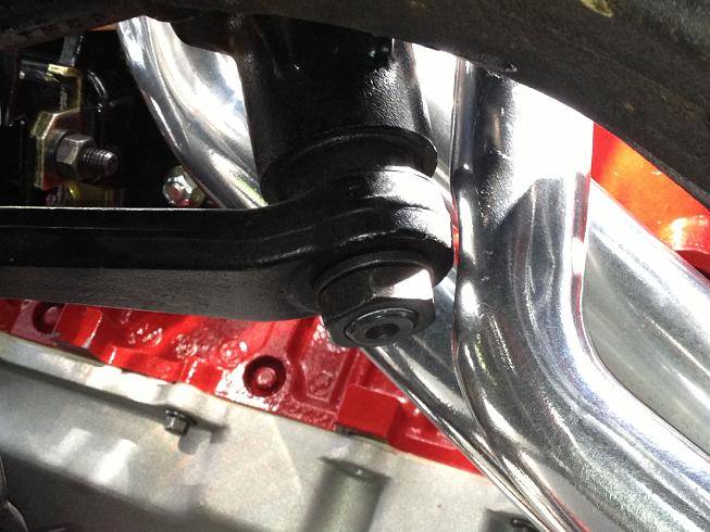
I forgot to mention two things. First is that I had the driver's side motor mount upside down, as you can see in the pics where the engine is still on the hoist. And second is that I ended up using the pre-load plate that Energy Suspension provides. My oil pan was either touching the front subframe crossmember or it was less than a paper width from it, so I used the pre-load plates as a 1/4" spacer. They also bought me some room for the headers (that still needed clearancing).
Here's a pic of the #7 tube in relation to the Pitman arm. As you can see, if I slide the motor forward at all it will hit:
-
05-20-2013 #308
Registered User
- Join Date
- Jan 2011
- Location
- Boston, MA
- Posts
- 1,180
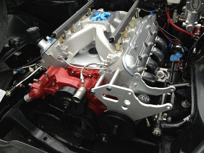
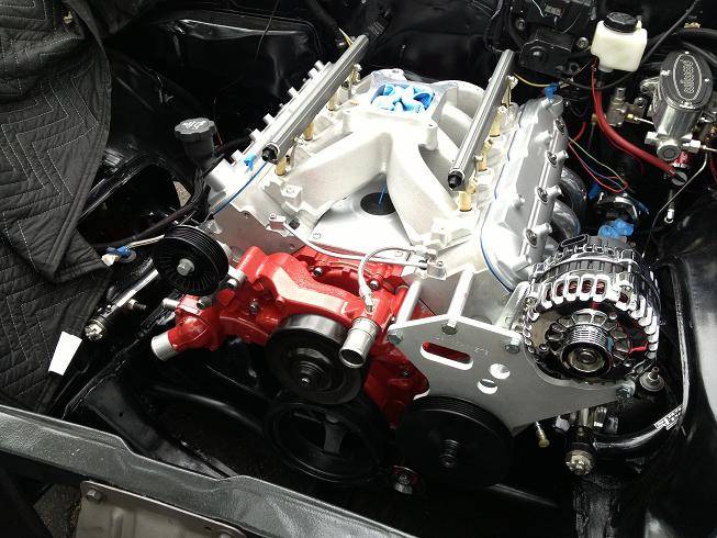
I got some more work done last night. I worked on the accessories. I couldn't stand the stock LQ9 power steering/alt bracket. It stuck the alternator way too high, so I'm using a bracket from LSBrackets.com. This retains the stock PS pump location but moves the alternator to the Corvette location. It comes with all the aluminum brackets, spacers, idler pulley bolts, and fit perfectly.
LQ9 bracket on left vs LSBrackets on right:
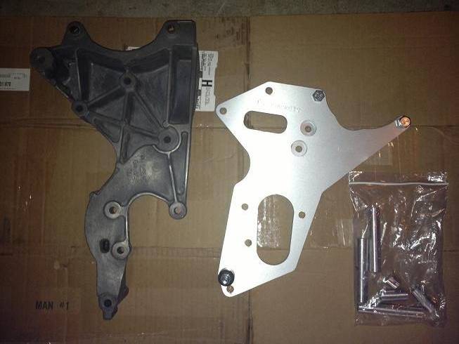
And here's the new bracket on top of the old one for comparison:
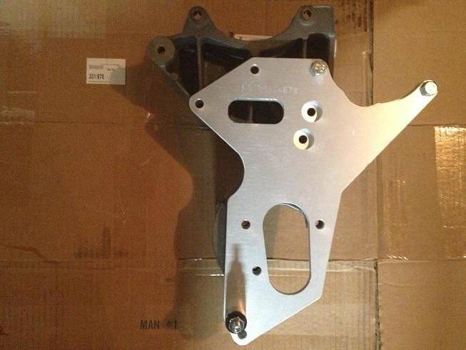
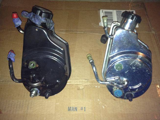
I also picked up a new PS pump from a 6.0 Silverado since it was shiny (LQ9 on left, Silverado on Right):
-
05-20-2013 #309
Registered User
- Join Date
- Jan 2011
- Location
- Boston, MA
- Posts
- 1,180
Here's the bracket mocked up, PS pump and pulley in place and below the PS pulley you can see the new idler pulley:
The new tensioner is installed (in front of passenger side head), and the car wouldn't be complete without a shiny chrome alternator:
-
05-20-2013 #310
Registered User
- Join Date
- Jan 2011
- Location
- Boston, MA
- Posts
- 1,180
And here's what I started on my lunch hour(s) today:
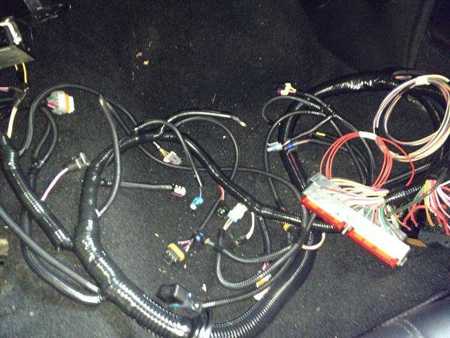
This would have gone quicker with someone pulling the wires from the engine bay side, while I fed them through the firewall. Instead I went back and forth a dozen times to get to this point (I also mounted the coils and coil brackets):
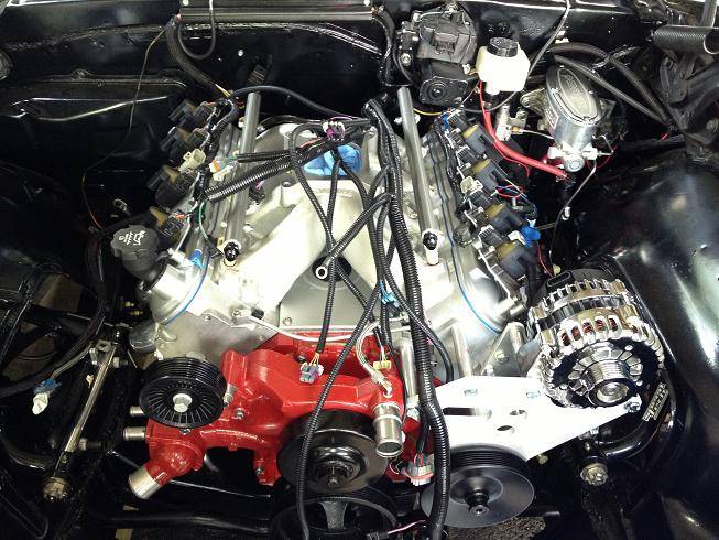
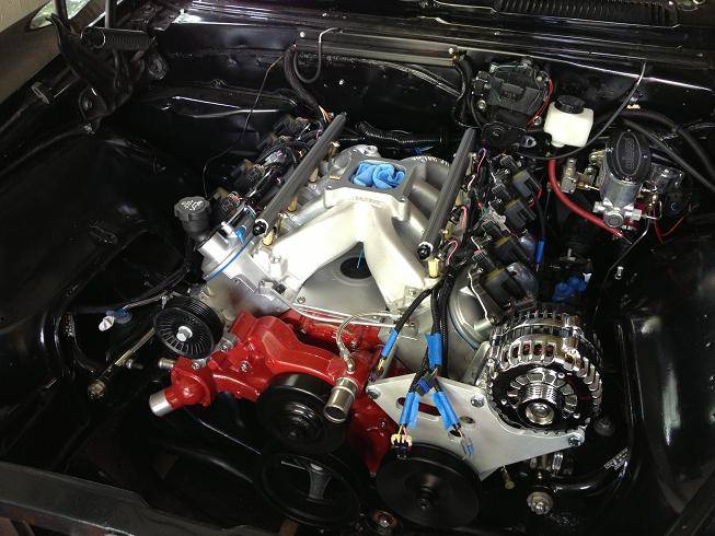
At this point I have about half of the wires hooked up in the engine bay. I will probably have to cut the harness open to re-route some of the sensor wires that go to the throttle body. Those are the wires up front with blue tape on them. Normally the TB would be located directly above the water pump, but because I'm using a 4 barrel TB mounted on top of the Vic Jr., the wires may not reach, and even if they do, they will not look very clean. I just need to remove the electrical tape on the loom, and pull a few of the wires back so they pop out closer to the firewall, then re-tape the loom.
-
05-21-2013 #311
Registered User
- Join Date
- Mar 2009
- Location
- Houston, TX
- Posts
- 1,197
Great progress.
Tu Ho
Firebird V2-LS swap
-
05-22-2013 #312
 Registered User
- Join Date
- Feb 2005
- Location
- Las Vegas, NV
- Posts
- 1,267
Great write up!!
I am in the middle of my LS/ T56 swap in my 68'Couple of questions:
1) did you have to shim your slave cylinder for proper travel?
2) did you have any fitment issues with your trans tunnel with the T56?
3) where are you mounting your engine pcm? I see where you drilled the hole in the firewall for the wires to feed through
Thanks, Jeff
-
05-22-2013 #313
Registered User
- Join Date
- Jan 2011
- Location
- Boston, MA
- Posts
- 1,180
1) No, I didn't need a shim for the slave cylinder. That's one of the reasons I went with the Monster clutch, since they say their clutches don't need shims. Originally Posted by jwcarguy
2) The T56 fit in the tunnel without touching anywhere, but there was one spot near the shifter that was fairly tight and I didn't want to have any vibration issues so I did give the tunnel a little clearance with a block of wood and hammer.
3) I haven't decided on the final location for the PCM. I have plenty of room right now since I don't have Vintage Air yet. I will mount it behind the glove box area, but realize I may have to move it in the future.
As far as the hole for the wires, I think it would have been better placed a few inches towards the passenger side with the PSI harness. It works fine, but the routing would be easier with the hole closer to the midline of the firewall.
-
05-23-2013 #314
Registered User
- Join Date
- May 2012
- Posts
- 19
I feel your pain. Getting headers to fit between the steering box and block has been a source of constant pain for me. I finally found a pair a semi-shorty headers about a year ago that fit fairly well, but still needed just a little convincing. Originally Posted by 67rally
Overall your build looks like it's going great! And considerably faster than mine. Good job! The wiring harness looks like a solid piece of hardware too.- Neil
- 1968 Camaro. Currently: SBC .040 over, 700R4, 10 bolt w/ 3.73's.
-
05-23-2013 #315
Registered User
- Join Date
- Jan 2011
- Location
- Boston, MA
- Posts
- 1,180
Thanks Oramac, the harness is very nice. Originally Posted by Oramac
I've been plugging away (pun intended) at the wiring this week, but haven't had much time. I did have to cut the harness open to move the IAT, IAC, MAP and TPS sensors to the rear/passenger side of the engine, and deleted my MAF sensor altogether since I won't be running it with the Vic Jr.
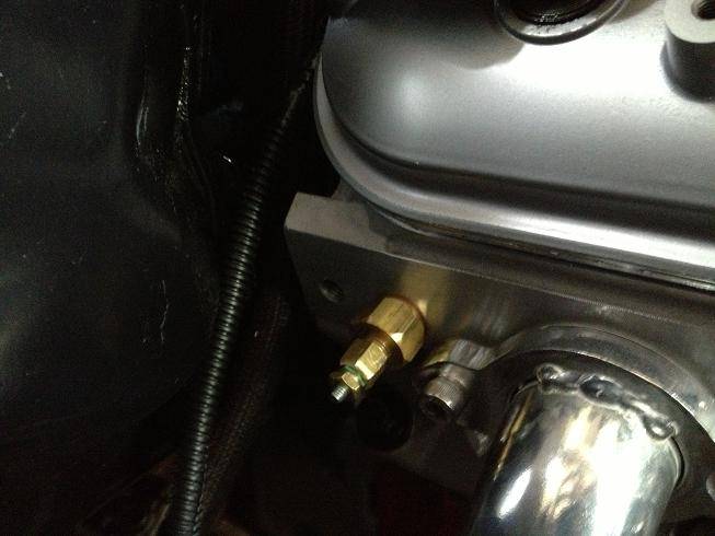
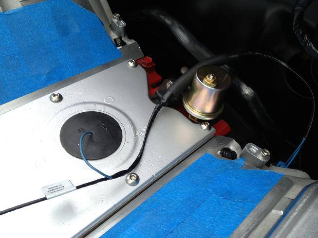
I also need to use my old oil pressure and coolant temp sensor for the gauges. The new coolant sensor in the front of the driver's side head that plugs into the harness will just send info to the PCM (ECU), so I'm actually running two coolant sensors. The coolant sensor for the gauges is in the rear of the passenger side head. Anyways, I ordered some adapters from NVU to go from 1/8"NPT to M12 (coolant) and M16 (oil pressure), since I'm running their gauges.
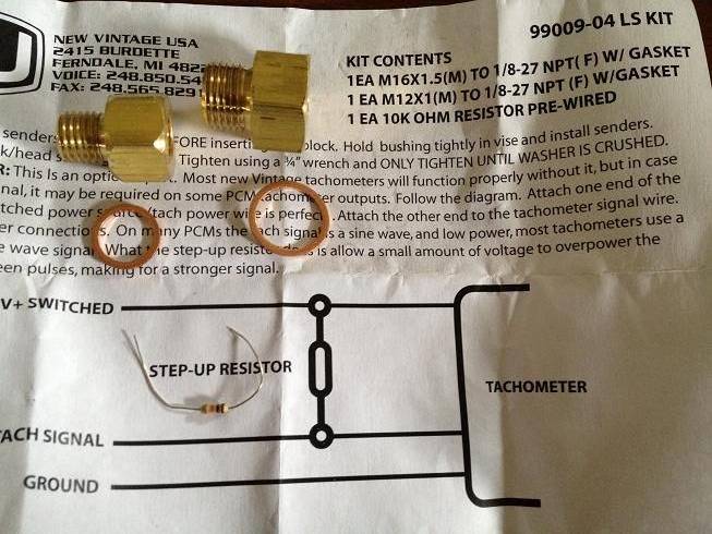
Coolant temp sensor for gauges with M12 adapter:
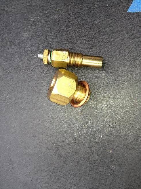
Installed:
Oil pressure sensor installed:
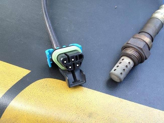
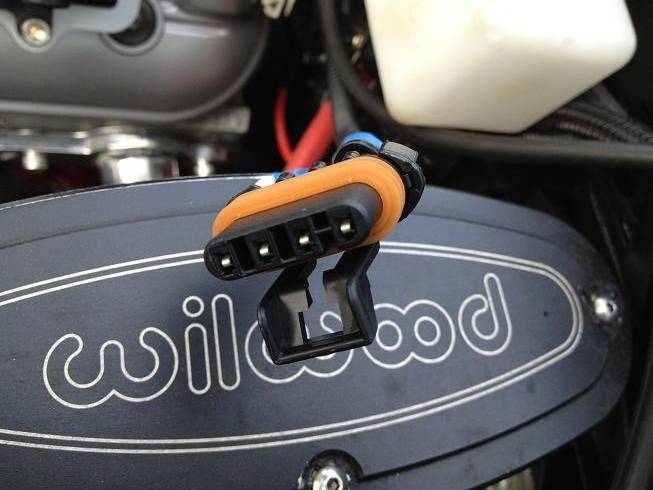
I also found out I can't re-use my LQ9 Oxygen (O2) sensors that screw into the headers. The harness is set up for a 4 wire flat connector and the LQ9 has a 3 wire triangular connector. No big deal, except new sensors are $60 each. I also need to pick up a couple of O2 sensor harness extenders since the sensors are about 8" too far away. Another $20 each. Luckily I know someone who might have a spare set of the right O2 sensors I can pick up for half price.
LQ9 O2 sensor and plug:
Here's the plug on the PSI harness (uses GM# 25312184 / Delco# AFS75):
That's it for a few days. I'm putting down the wrenches and heading North for a long weekend.:beers:
-
05-23-2013 #316
Registered User
- Join Date
- Jul 2005
- Location
- Grain Valley, MO
- Posts
- 92
Again, your pictures are very very helpful. I mounted my NVU gauges after work today since I was dying to have made my first step towards the build. We're running the same PSI harness so let me know how you set up the tach gauge if you would please.
Curious though, does the computer need to see oil pressure from the factory sender or are we ok to ditch it?
-
05-24-2013 #317
Registered User
- Join Date
- Jan 2011
- Location
- Boston, MA
- Posts
- 1,180
Glad I can help. You can ditch the factory oil pressure sender, the computer doesn't need to see it. It just needs to see the coolant temp so it can signal the electric fan(s) to come on at a given temp. Originally Posted by Mizzouri
05-24-2013 #318 Registered User
- Join Date
- Jan 2006
- Location
- Melbourne, Fla
- Posts
- 216
Brent,
Looking great! You should be firing her up this weekend! Post a vid!
TC
05-24-2013 #319
Registered User
- Join Date
- Jan 2011
- Location
- Boston, MA
- Posts
- 1,180
Lol, I wish. I'm 250 miles away from her at the moment. And I still have a lot of loose ends to tie up, plus need a base tune on the ECU as well. Originally Posted by Tango68SS
05-29-2013 #320
Registered User
- Join Date
- Jan 2011
- Location
- Boston, MA
- Posts
- 1,180
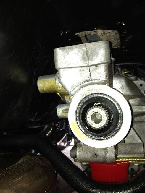
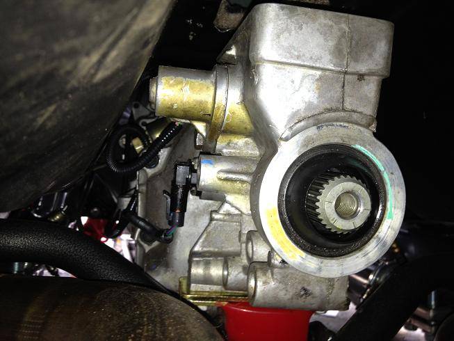
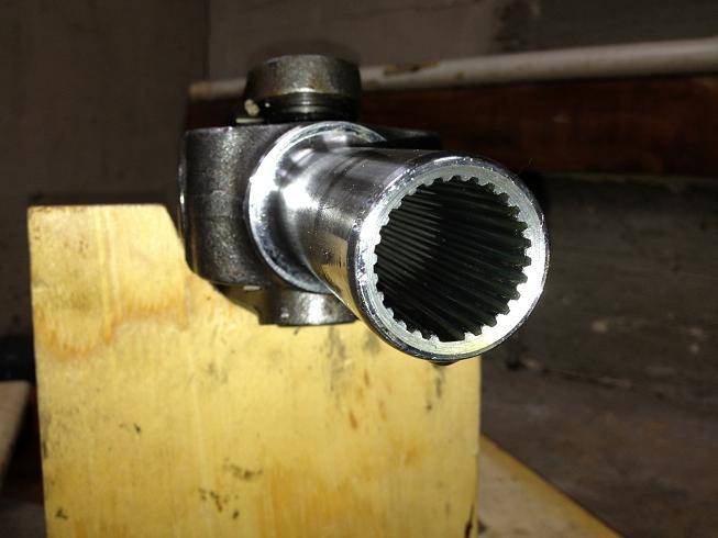
I hit a roadblock in the build today. I spent two hours under the car trying to install my old drive shaft so I could measure to have it shortened. This driveshaft has less than 1000 miles and no real abuse on it. It was mated to a Saginaw tranny which is a 27 spline output shaft. The T56 came out of a running/driving GTO and also has a 27 spline output shaft. From everything I read the two use the same slip yoke.
I couldn't even get the driveshaft to start sliding in. I had cleaned both parts thoroughly with brake cleaner and then lubed them up and got nowhere. I took pics of the output shaft and of the slip yoke and they both look clean. No obvious dings or twisted splines. I ran out of time today, so I'll get back under there tomorrow and see if the tail shaft bushing is a different size in the T56 vs the outer diameter of the yoke. I'm open to any words of wisdom here, apart from "did you try it when it was out of the car?" The answer to that is a resounding no.:sad:


 Reply With Quote


 Tango Charlie





