Results 261 to 280 of 573
-
04-16-2013 #261

 Registered User
- Join Date
- May 2009
- Location
- Elkhart, IN
- Posts
- 54
Man, that motor is going to be awesome in there.
Lots of Neon's
Harley NRS
Trx250r
69 Camaro: Under Construction Small Block (Soon LSxT)
http://www.cardomain.com/id/teamvpneon
Used to be known as teamvpneon
-
04-16-2013 #262
Registered User
- Join Date
- Feb 2013
- Location
- DFW
- Posts
- 8
 You are correct. I used a quick online calculator instead of writing it out and may have typed in a wrong number.
 Originally Posted by 67rally

(231+235)/2 = 233
(2x10⁸) = 216
233-216 = 1709 G8 GT - Daily
68 C10 - Project
04-17-2013 #263 Registered User
- Join Date
- Jan 2011
- Location
- Boston, MA
- Posts
- 1,180
You may have used 235/239 for the intake/exhaust? I remembered coming up with 21 degrees when I was looking at cams and thought that was a bit lumpy! Originally Posted by HammerBuilt
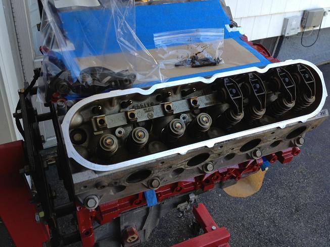
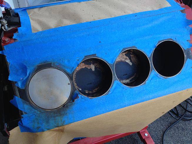
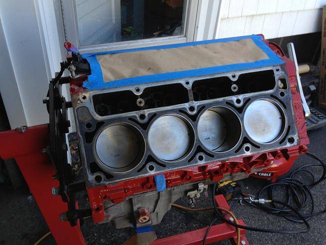
I made a little more progress. If my new cam retainer plate arrives by the weekend, then the new cam, timing chain, oil pump and heads are going on. Today I pulled the old heads, cleaned up the old head gasket and cleaned the pistons. I used brake cleaner and a soft bristled cup brush on my dremel, and they came out nice and clean. I taped everything off so I wouldn't end up with any debris in the engine. The flat top pistons confirm that this is an LQ9 motor. The LQ4 would have had dished pistons and lower compression.
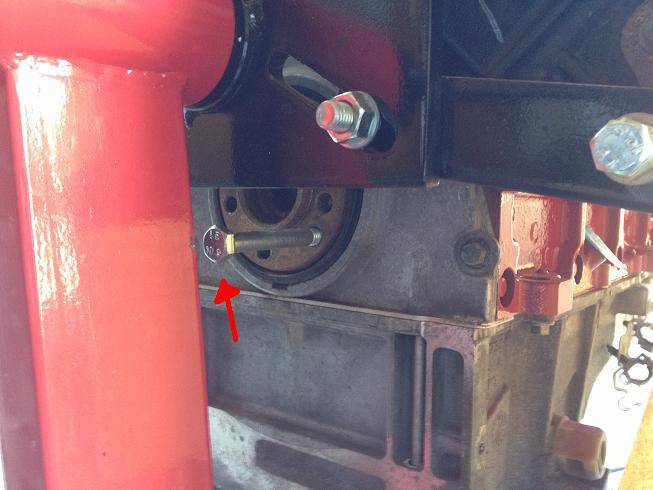
And I forgot I put this bolt in when I was removing the crankshaft bolt last time. I put it there so the bolt would catch on the engine stand and allow me to loosen the crank bolt. Well, when I went to turn over the engine to clean the pistons, I got about a half revolution and the motor felt like it was seized. I backed it off and tried again and had the same result. I went into panic mode for a second, but remembered it turned over fine a few months ago. Well, long story short, the bolt was still there and doing exactly what it was supposed to do. Doh!:o
04-18-2013 #264
Registered User
- Join Date
- Jan 2011
- Location
- Boston, MA
- Posts
- 1,180
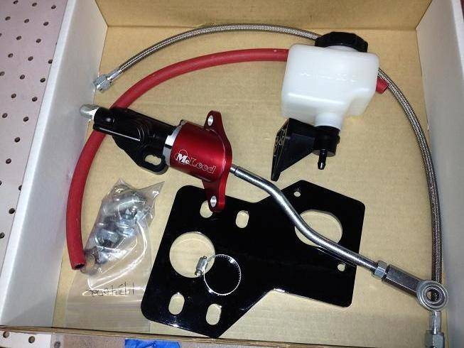
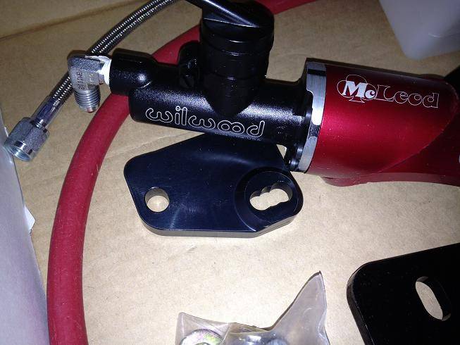
Another package arrived today, this one's from Jegs. This is the 1967-1969 Hydraulic Clutch Conversion Package from McLeod Racing (and Wilwood). Part # 1434002: http://www.mcleodracing.com/info/?id=5514. It's a complete kit to convert from a mechanical to a hydraulic clutch for our cars (master cylinder, reservoir, bracket, bolts, hydraulic line, hose, clamps, etc.)
Here's where I started:
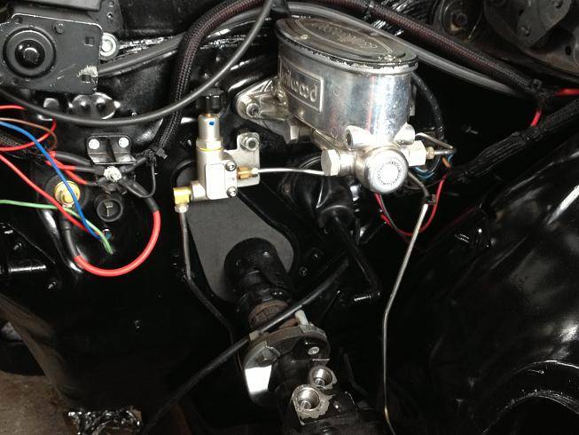
The Wilwood brake master cylider had to come off, and since it's pretty tight under the dash, I pulled the steering column as well:
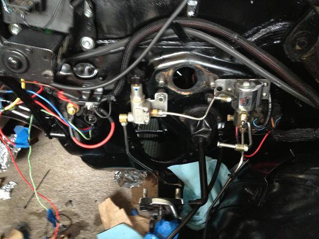
I moved the Wilwood proportioning valve and Hurst Roll Control out of the way. Then I attached the clutch MC to the supplied bracket and mounted it to the firewall:
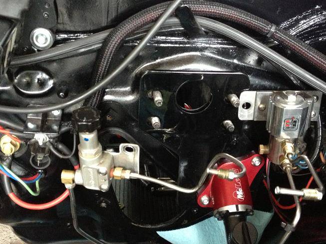
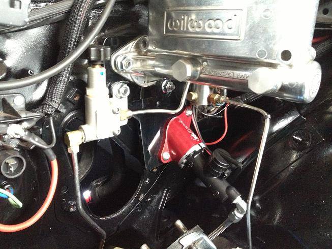
Everything's back together. I'll put the steering column back in tomorrow. I was getting thirsty...:beers:
04-24-2013 #265
Registered User
- Join Date
- Jan 2011
- Location
- Boston, MA
- Posts
- 1,180
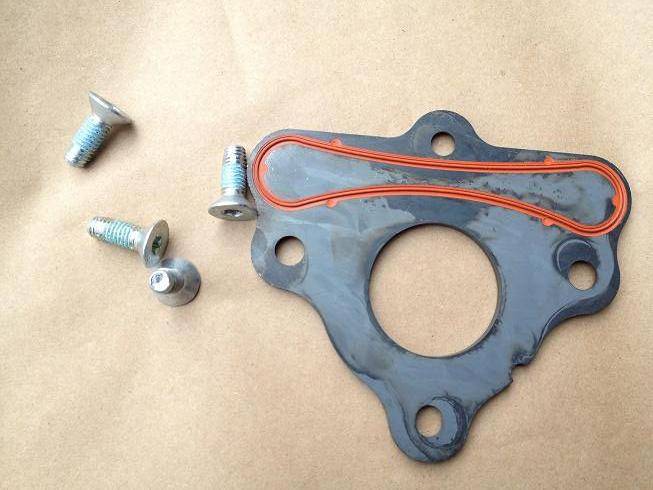
Finally 10 days after I ordered my replacement cam retainer plate, it arrived from gmpartsdirect.com. I don't think I'll use these guys again, I found a lot of bad reviews after ordering from them. Anyways, now I can start the cam swap.
Here's the cam retainer plate and bolts. The new plate has recessed bolts, so the old ones can't be re-used:
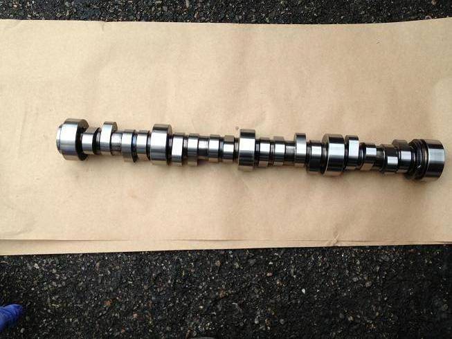
Comp Cams custom grind, 231/235 .617"/.621" on a 108 LSA. Should be lumpy.
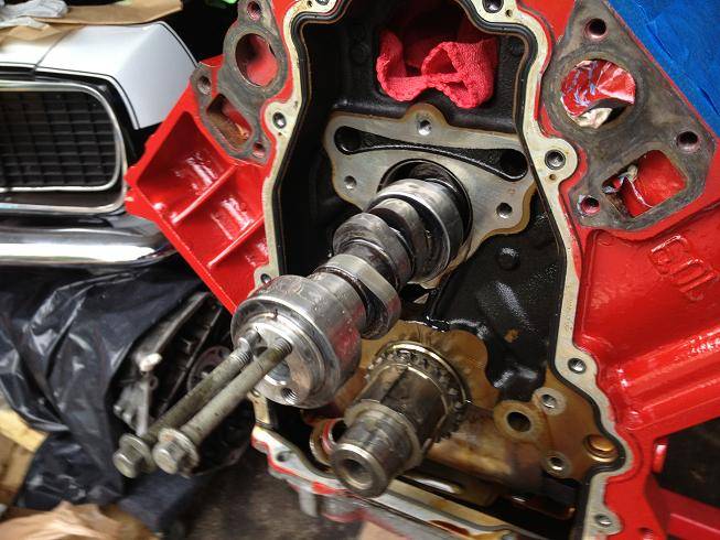
New cam going in, I used the water pump mounting bolts as a handle:
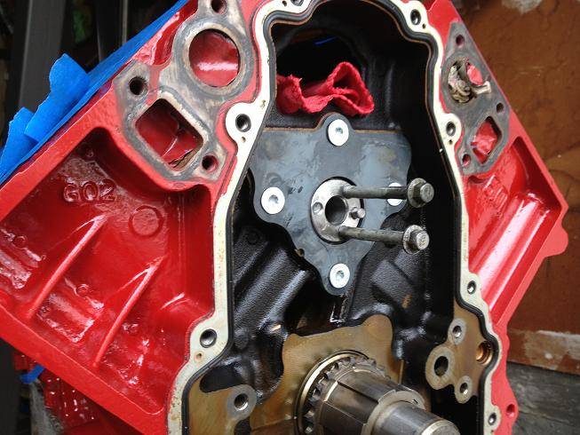
With the retainer plate:
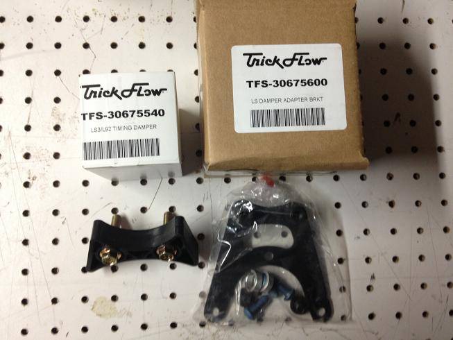
The 6.0 LQ engines don't have any bolt hole provisions for a timing belt tensioner, but the LS2 engines do. I wanted to use an LS2 damper, so I got an adapter bracket and damper from Trick Flow:
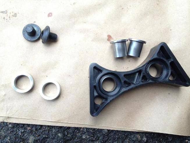
The kit requires you to knock out the metal oem load bushings and replace them with newly supplied bushings:
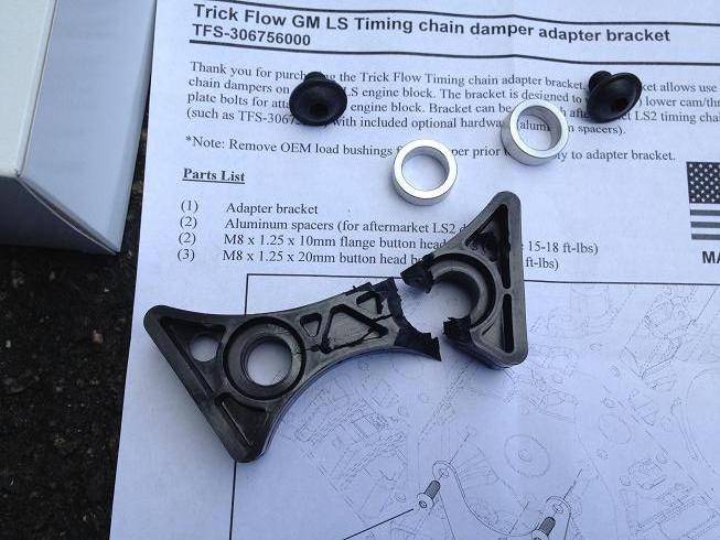
The LS2 damper was very tight going onto the bracket studs, so I used a block of wood and a rubber mallet to gently tap it into place. Just when I thought it seated, I heard a pop and a piece of plastic ricocheted off my leg:
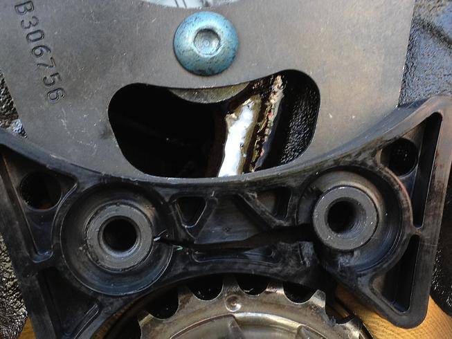
I called Trick Flow and they said the tolerances were extremely tight and while they hadn't had any break, they didn't blame me. I called TEA where I got the damper from, and he's sending a new one out, to be here before the weekend:
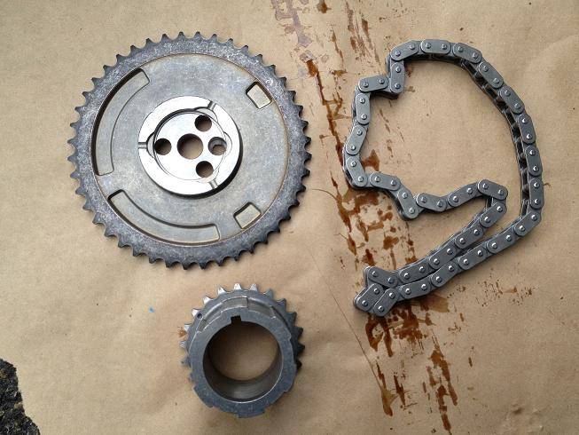
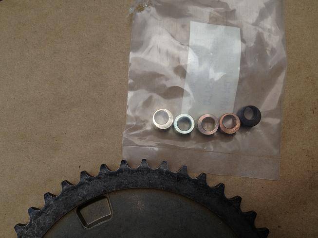
Here's the Yank LS2 adjustable timing chain set. They modify a stock timing chain gear, by drilling out where the cam dowel goes and supply a number of inserts to adjust the timing. All the changes are made to the cam gear, and not the crank sprocket. This way if you need to advance or retard the cam, you don't have to remove the oil pump.
Close up of the inserts:
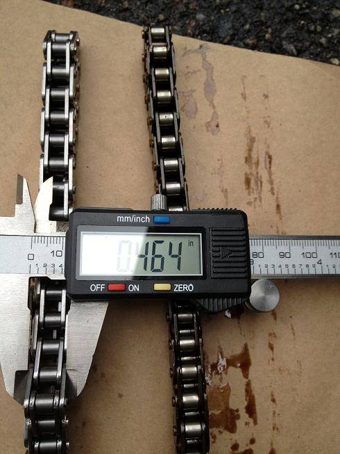
Here's the LS2 chain on the left next to the LS1/LQ9 chain on the right. The LQ9 chain was .433 thick vs the LS2's .464. It's a much stronger chain, without going to a double roller (added mass):
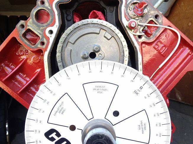
I degreed the cam, and it was within 1 degree of where it was supposed to be, so I'm happy with that:
04-25-2013 #266
Registered User
- Join Date
- Jan 2011
- Location
- Boston, MA
- Posts
- 1,180
Nice day today, so I cut out of work a little early. I'm hoping that LS2 tensioner arrives by the weekend, so I can really start the re-assembly. I stopped by the local Chevy dealer to see if they had the part in stock, which they didn't, but the closest part is about 40 minutes away. I may make a road trip on Saturday if I don't get the replacement in the mail.
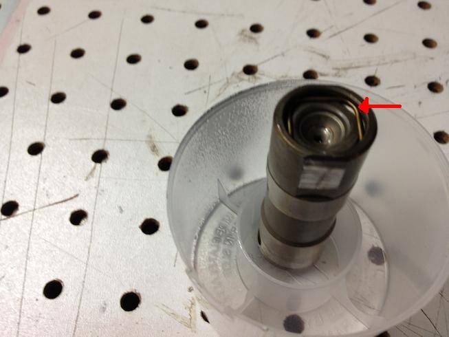
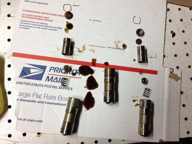
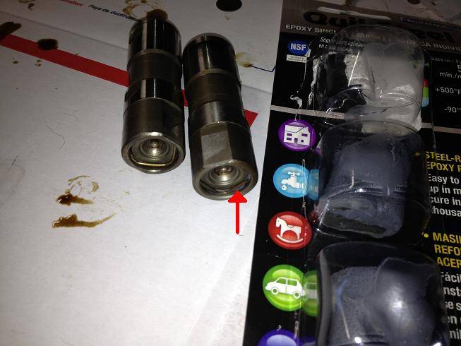
In the meantime, I decided to check my piston to valve (PTV) clearance, since I had the heads milled a little, and I'm running a decent sized cam. I made a couple of solid lifters out of the old LQ9 hydraulic lifters. I just dissasembled them, removed the springs, and then filled them with some QuikSteel epoxy (same as Steel-Stick).
Remove this retaining clip:
Here's what the lifters look like pulled apart:
Here they are re-assembled, you can see a little of the steel epoxy by the arrow:
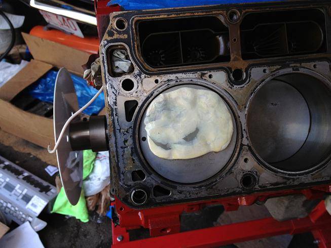
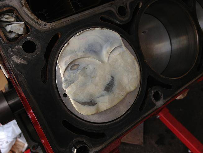
I re-used my old head gaskets for the test, since the new ones are the same thickness. (they look nasty, but I degreased and scrubbed them, and cleaned them with brake cleaner.) And then added a lump of modeling clay to the area where I thought the valves would hit, and rubbed a little oil on the top so it would release from the valve. I had to mix some white and gray clay to get enough for the test. At least I didn't use the bright orange:
Here's one of the new ported TEA 243 heads going on and torqued down to 30 lb/ft for the test:
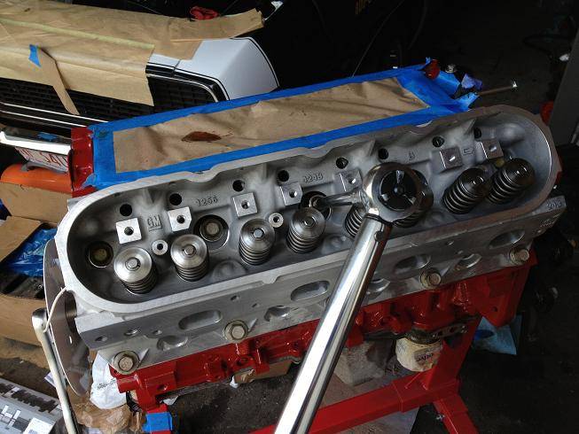
7.4" pushrods:

I forgot to take a pic with the rocker arms on, but they go on and set to zero lash. Then I rotated the engine over 2 full revolutions and pulled the heads back off:
04-25-2013 #267
Registered User
- Join Date
- Jan 2011
- Location
- Boston, MA
- Posts
- 1,180
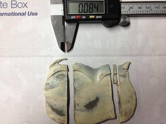
Then I cut the modeling clay half and used a micrometer to measure the thickness at the thinnest point. You want a minimum of .080" on the intake side and .100" on the exhaust side to ensure you won't have any PTV issues. Some people have run as little as .050"-.060" and gotten away with it, but it's a little risky. Too little PTV and you'll have to flycut the pistons or risk piston to valve kiss and the mayhem that ensues. I ordered my cam as large as possible without having to flycut the pistons or having to use a thicker head gasket.
.084 on the intake:
.104 on the exhaust:
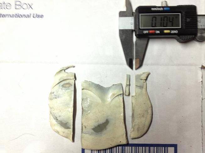
I wouldn't want it any tighter.....
04-26-2013 #268 Registered User
- Join Date
- Aug 2006
- Posts
- 381
Great progress man. I got the same EFI tank but ordered it from Aeromotive and it came with aeromotive fuel pump and the sending unit, both of which were preinstalled on the tank. Originally Posted by 67rally
However, the powdercoating on my tank was a bit in bad condition in some areas. So i might need to touch up some areas if possible or repaint the entire tank.
I really like where you mounted the supplied check valve and the way you Teed it with the ridetech vent line. I guess i am going to do the same thing.
As for the Tee fitting, could you please provide the part no and where you got it from?
Also, are you using a stainless steel fuel line that was pre cut for your car or you had to fabricate your own?72 Camaro RS:SOLD
68 Camaro:
LS6 Engine,Tremec TKO 600,5 Speed
Complete Speedtech Subframe Kit,Speedtech Torque Arm, 9" Rearend from Strange, Wilwood Brakes, Minitubbed, Hotchkis Subframe Connectors
04-27-2013 #269
Registered User
- Join Date
- Jan 2011
- Location
- Boston, MA
- Posts
- 1,180
Thanks. I picked up that T fitting at Autozone or PepBoys. It's just a brass barbed T fitting. I've seen them at Home Depot as well. I just grabbed one with that fit the I.D. of the hose. I don't think I have a part number for it. Originally Posted by 72Z/28
I'm using pre-cut stainless steel fuel lines from Inline Tube. They are the 3/8" lines: http://inlinetube.com/Preformed%20Li...es/CCF6701.htm
04-27-2013 #270
Registered User
- Join Date
- Mar 2009
- Location
- Houston, TX
- Posts
- 1,197
What are you using fitting wise to go from the steel lines to the AN lines? Compression fitting/an line adapter? Originally Posted by 67rally
Tu Ho
Firebird V2-LS swap
04-27-2013 #271
Registered User
- Join Date
- Jan 2011
- Location
- Boston, MA
- Posts
- 1,180
Huh, I took pics and I was sure I posted that info, but as I look back at the thread I can't find it either. Originally Posted by rickpaw
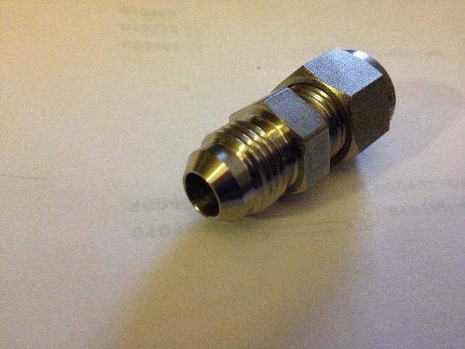
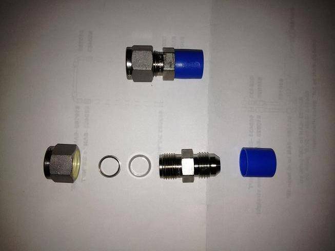
Yes, they are stainless steel compression fittings, 3/8 tube to -6AN from Swagelok. The part number is SS-600-6-6AN. They were the only company I could find that sold the fitting in SS, rather than aluminum
04-27-2013 #272
Registered User
- Join Date
- Mar 2009
- Location
- Houston, TX
- Posts
- 1,197
Great. Thanks for the info. I just got the tanks inc plumbed up this afternoon. I'm hoping to mount mine up tomorrow.
Tu Ho
Firebird V2-LS swap
04-27-2013 #273
Registered User
- Join Date
- Jan 2011
- Location
- Boston, MA
- Posts
- 1,180
Cool. Originally Posted by rickpaw
04-27-2013 #274
Registered User
- Join Date
- Jan 2011
- Location
- Boston, MA
- Posts
- 1,180
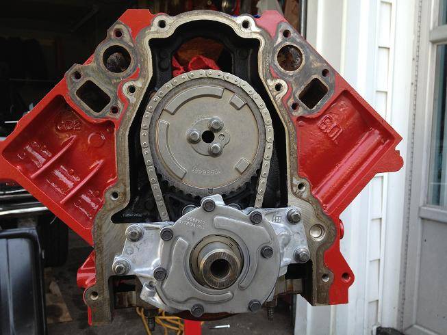
Made some progress, took more pics along the way.
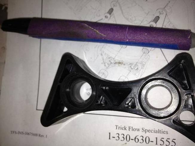
My new timing chain tensioner arrived from Trick Flow. I tried to fit it and it fit as poorly as the last one I broke. The bolt holes on the tensioner don't line up with the bracket. The bracket's posts are spaced a little too wide. Interesting, since both parts come from the same company. I had to clearance the tensioner a little by boring the holes out towards the midline. I wrapped some 220 grit around a Sharpie and filed away until it would fit:
Here it is mounted to the engine:
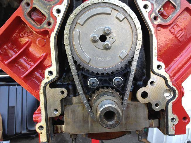
The bracket is tight against the engine, the tensioner is tight against the bracket, the bushings are seated all the way and when I went to bolt up the new oil pump, I had major clearance issues:
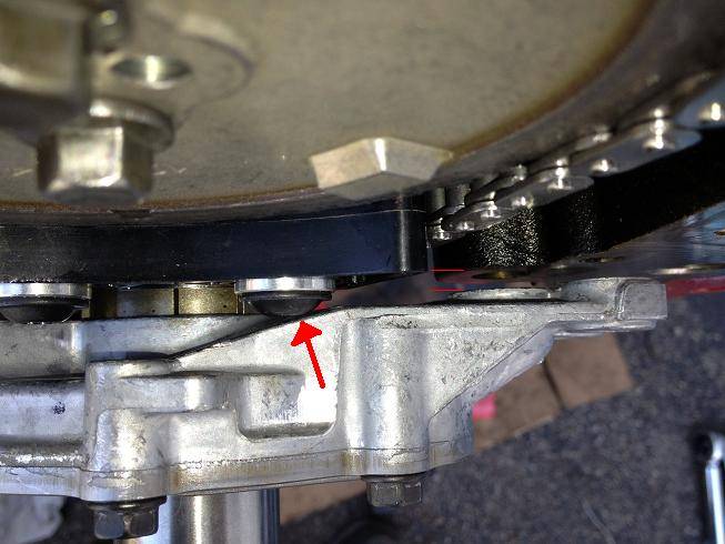
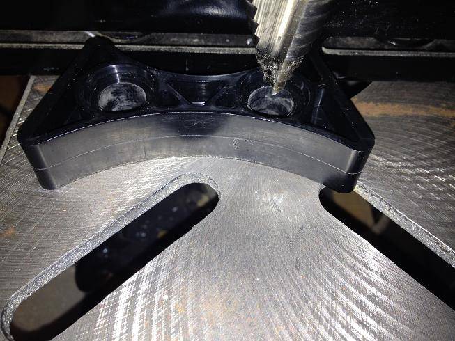
I had to drill the bushing recess a little deeper. I started with a step bit, but switched to a forstner bit. I went about 3/16".
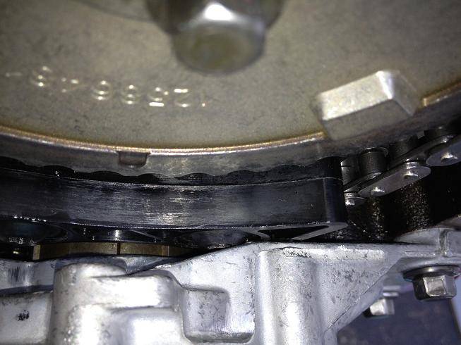
Finally the oil pump fit tight against the engine:
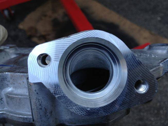
Here's a shot of the port work done on the oil pump:
And here it is mounted:
04-27-2013 #275
Registered User
- Join Date
- Jan 2011
- Location
- Boston, MA
- Posts
- 1,180
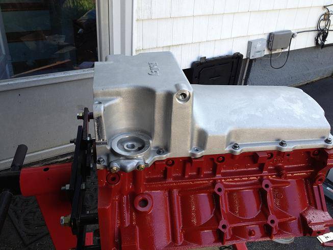
Next it was on to the new Holley LS Retrofit oil pan. Old oil pan removed, pick up tube removed and windage tray cleaned up:
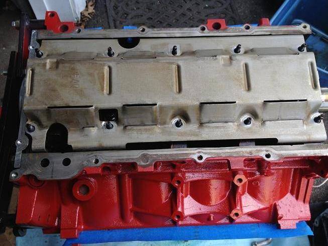
Holley says you may have to modify your windage tray if the pick up tube doesn't mount flush. Why wouldn't you have to clearance it right? I mean, it's not like you're buying a retrofit part specifically designed for your car right? Oh, yeah, it is...
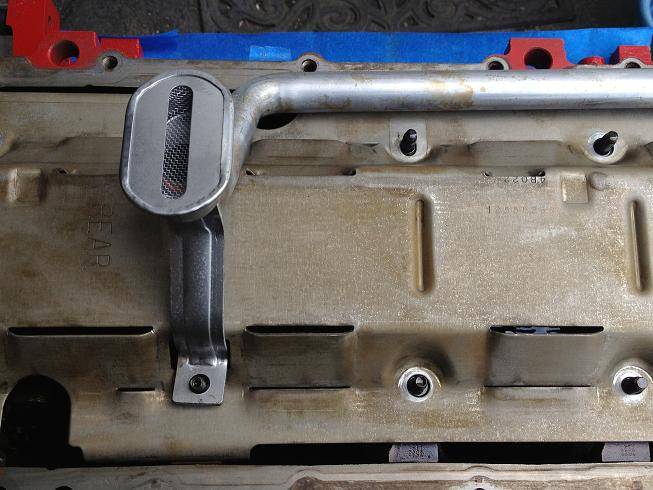
Doesn't sit flush, I used a razor blade to mark where I'd need to cut:
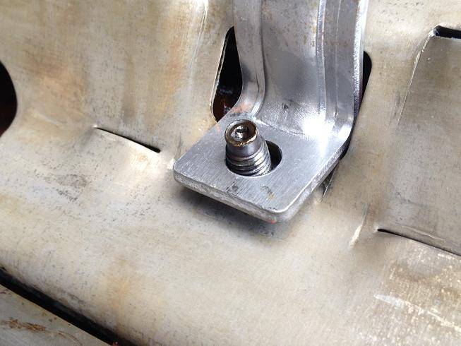
Then went over it with a sharpie:
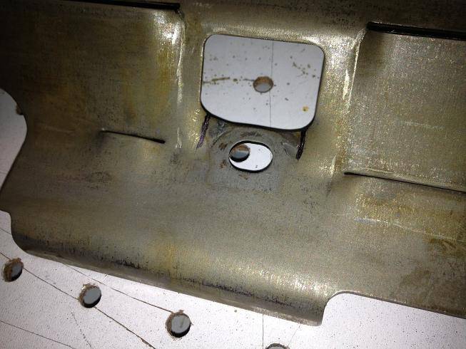
A dremel with a cutoff wheel and then a couple whacks with a hammer:
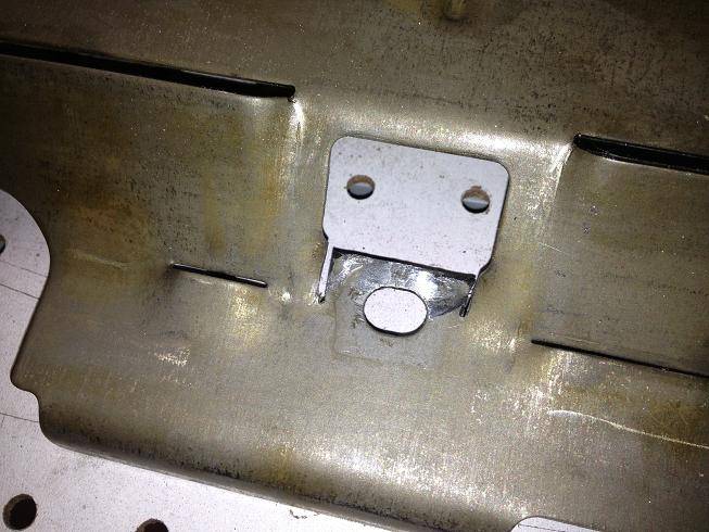
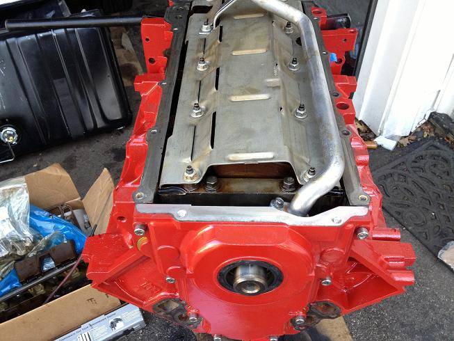
Assembled on the engine:
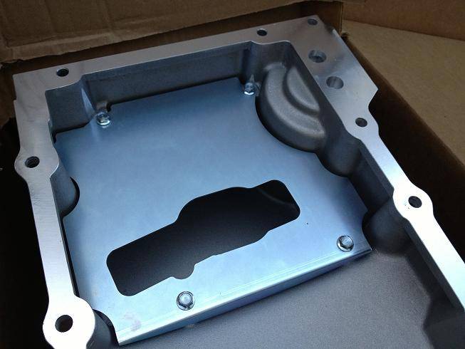
Here's the baffle inside the Holley pan:
And this is where I left off, front cover gasket and oil pan gasket in place with a little RTV sealant along the edges where the front cover and rear cover meet the engine. Oil pan bolted on, front cover on. Tomorrow I can start on the heads:
04-27-2013 #276 Registered User
- Join Date
- Dec 2005
- Location
- Birmingham, AL
- Posts
- 3,355
This thread has some great detail in it. Thanks for taking the extra time you took to document the build.
Stephen
04-30-2013 #277
Registered User
- Join Date
- Jan 2011
- Location
- Boston, MA
- Posts
- 1,180
No problem. I learned everything from reading other people's threads. Just passing it along. Originally Posted by srh3trinity
I'm on my final push ordering parts. The CC to a big hit this week. I just ordered all new sensors for the engine, along with a new alternator (don't ask what happened to the perfectly good one that I removed, tried to disasemble and took a 5lb BFH to...), gaskets, bolts, hoses, new Monster level 2 clutch, slave cylinder, speed bleeder, and probably some other goodies that will be a surprise when they arrive.
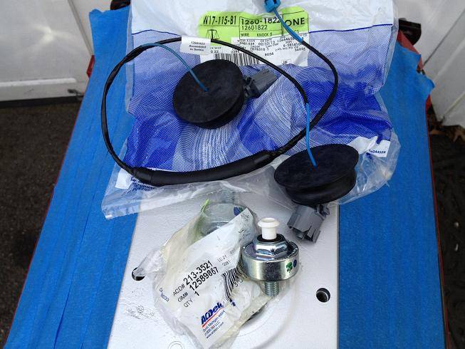
Installed the new knock sensors and wiring harness in the valley cover. These engines seem to have an issue with water leaking in around the big black rubber grommets, and mine was no exception. This results in rusted out knock sensors. I layed down a bead of black RTV before installing the grommets to prevent this in the future:
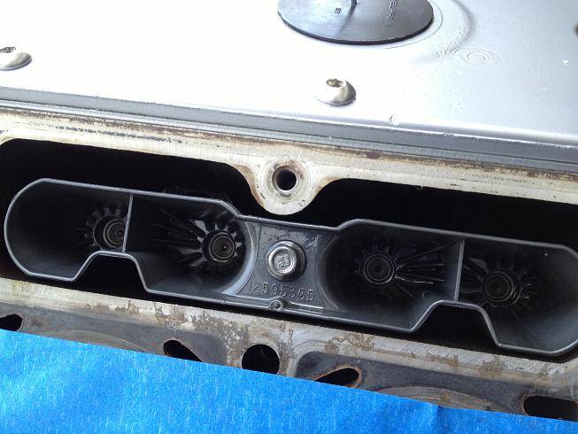
LS2 lifter trays, these hold the roller lifters in the right direction and are a nice upgrade from the LS1/LQ9 stuff. You can see the tops of the LS7 lifters that I upgraded to as well:
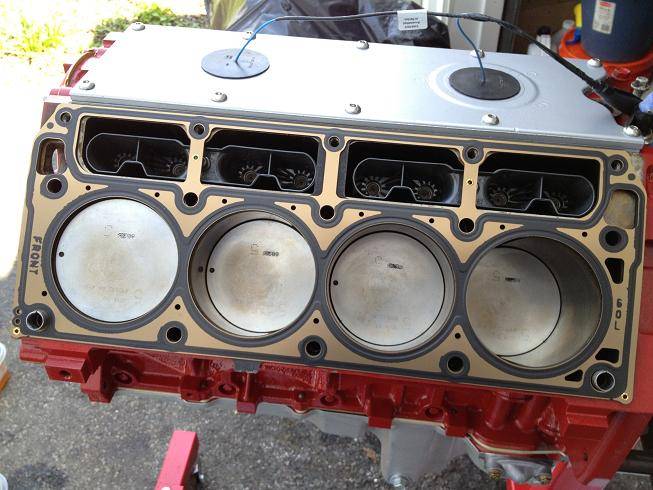
OOOO, head gasket is on, you know what that means...
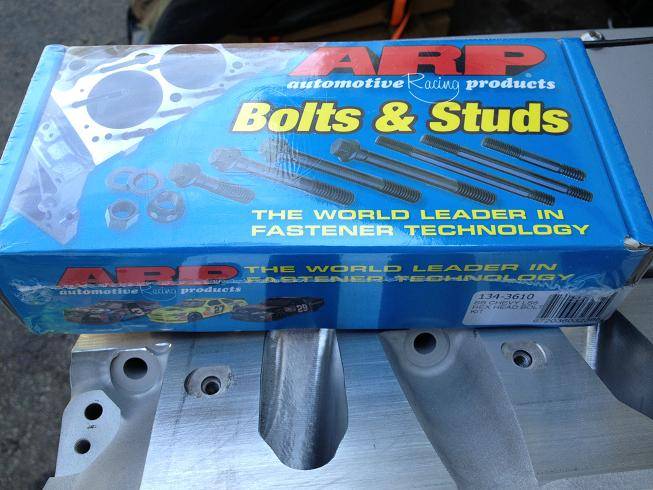
ARP head bolts:
05-01-2013 #278 Registered User
- Join Date
- Jul 2007
- Location
- Olathe, KS
- Posts
- 1,158
I'm not sure if it was stated previously, but what design are those headers? I understand they were sourced on ebay, but most I've seen there are typically based on other well known designs.
05-01-2013 #279
Registered User
- Join Date
- Jan 2011
- Location
- Boston, MA
- Posts
- 1,180
They look like they could be knockoff's of Doug's or Hooker headers. Both designs look just about the same to me. I'll be bolting them up in a couple of weeks and if they don't fit, they'll get the BFH treatment just to get me up and running. Originally Posted by Rhino
05-04-2013 #280
Registered User
- Join Date
- Jan 2011
- Location
- Boston, MA
- Posts
- 1,180
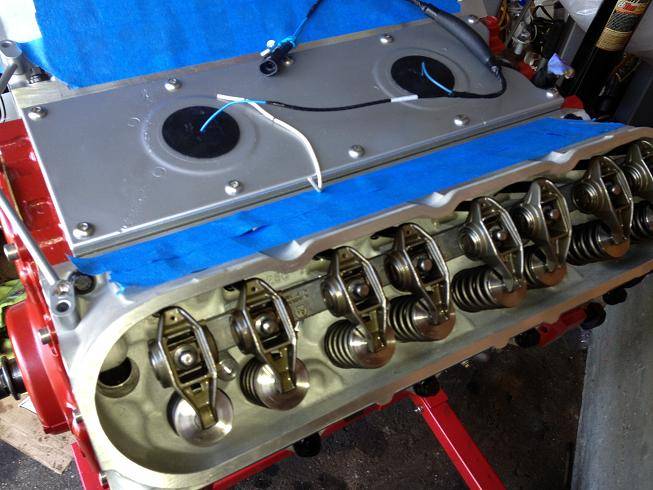
Installed the pushrods, rocker arms and torqued the bolts down today. GM recommends torquing to 22 lb/ft for a stock setup, but with a bigger cam the recommendation is 24-26 lb/ft from many builders. So I went with 25 lb/ft.
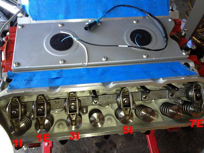
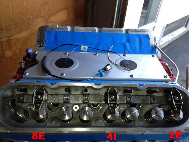
With cylinder 1 at TDC on the compression stroke, I torqued down the intake rockers for cylinders 1, 3, 4 and 5; as well as the exhaust rockers for cylinders 1, 2, 7 and 8. Just remember that the LS engine has a different IEIEIEIE pattern than the SBC's EIIEEIIE.
For quick reference these are the drivers side rocker arms you torque down with cyl 1 at TDC on the compression stroke:
And these are the passenger side rocker arms you torque down:
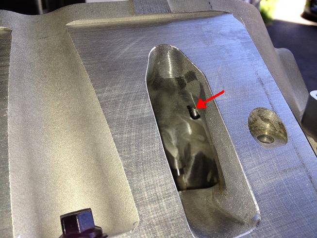
With any ported head, you need to look down the intake port to see if the port work has left the rocker arm bolt holes exposed. If so, you need to add a little RTV to the rocker arm bolts before installing. I added the RTV to both the intake and exhaust rocker arm bolts so my torque readings would be consistent. Here's a bolt showing through the intake side:
And here's the finished product:

 Reply With Quote