


Results 521 to 540 of 573
-
02-22-2017 #521
 Registered User
- Join Date
- Nov 2012
- Posts
- 5

I am glad I stumbled across this build. I have many of the same components / issues and I am going to upgrade the suspension / brakes in stages as well. I have the same clutch kit and a gto trans the clutch stop is good advice. I did have one related question do you remember where you put the bolt for the clutch rod? I have three options in the adapter block and I would guess the bolt is not going to want to come out once it is installed.
-
02-23-2017 #522
 Registered User
- Join Date
- Jan 2011
- Location
- Boston, MA
- Posts
- 1,180
I just spent half the day under my dash yesterday working on the Hydratech hydroboost pedal setup (yet another long story where nothing fits like it's supposed to), but never looked at the clutch pedal. I don't think I'll have a chance to look at it today, but I can look tomorrow and let you know. Originally Posted by starjunor

FWIW, the Hydratech setup does not play nicely with the McLeod master cylinder bracket on the firewall (I've heard there are issues with the ATS bracket as well). I'll post up some pics tomorrow, but the McLeod bracket sits flat against the firewall, and then angles out at the bottom. The Hydratech unit is supposed to sit flush against the firewall on the same bolts, so it hits the McLeod bracket at the bottom. Pics will help show what I did a little better.
-
02-24-2017 #523
Registered User
- Join Date
- Jan 2011
- Location
- Boston, MA
- Posts
- 1,180
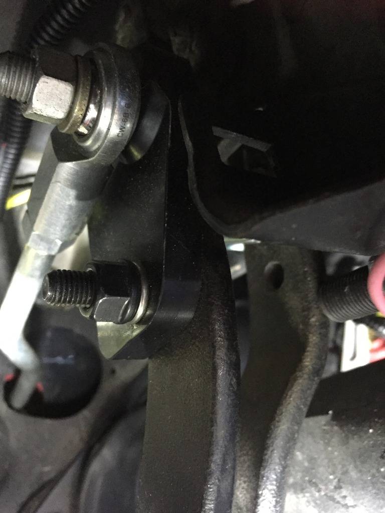
I only had one option in my adapter block. Maybe they changed the kit.
-
02-24-2017 #524
Registered User
- Join Date
- Jan 2011
- Location
- Boston, MA
- Posts
- 1,180
Time for an update. Everything has taken twice as long as planned with this round of upgrades. Nothing just bolts on anymore, I've come to the conclusion that anything I order will need to be mocked up, modified, test fit, modified, refit, modified, test again, BFH, it fits!
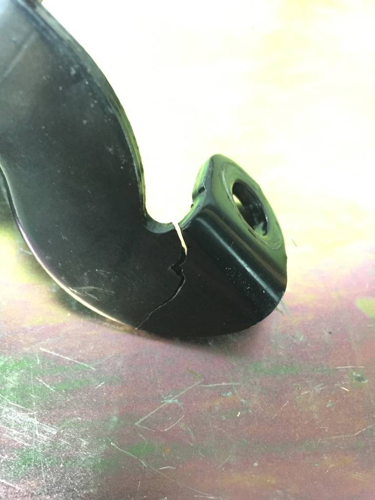
I replaced my PS pump with a new one designed for a hydroboost application, it just has an extra return port on it (2 instead of 1). In the process, I noticed this "little" crack in one of my PS brackets. This is probably from trying to overtighten the pressure fitting with the PS pump still mounted. I just v-grooved the crack and welded it back up. No after pics. Not very exciting.
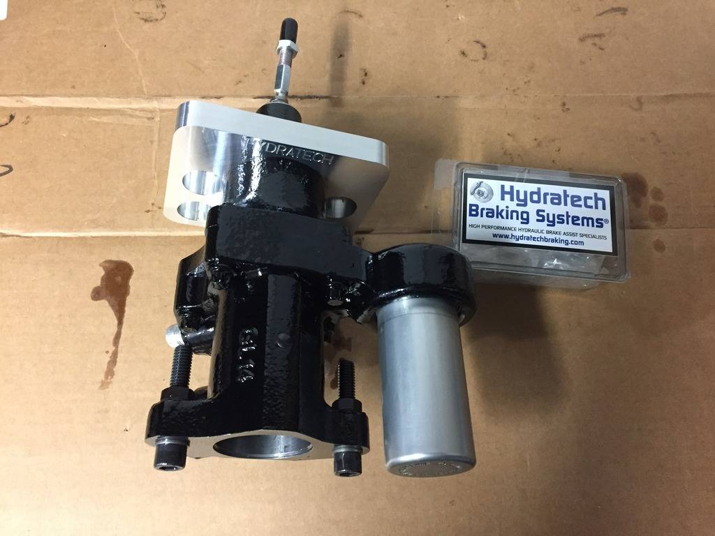
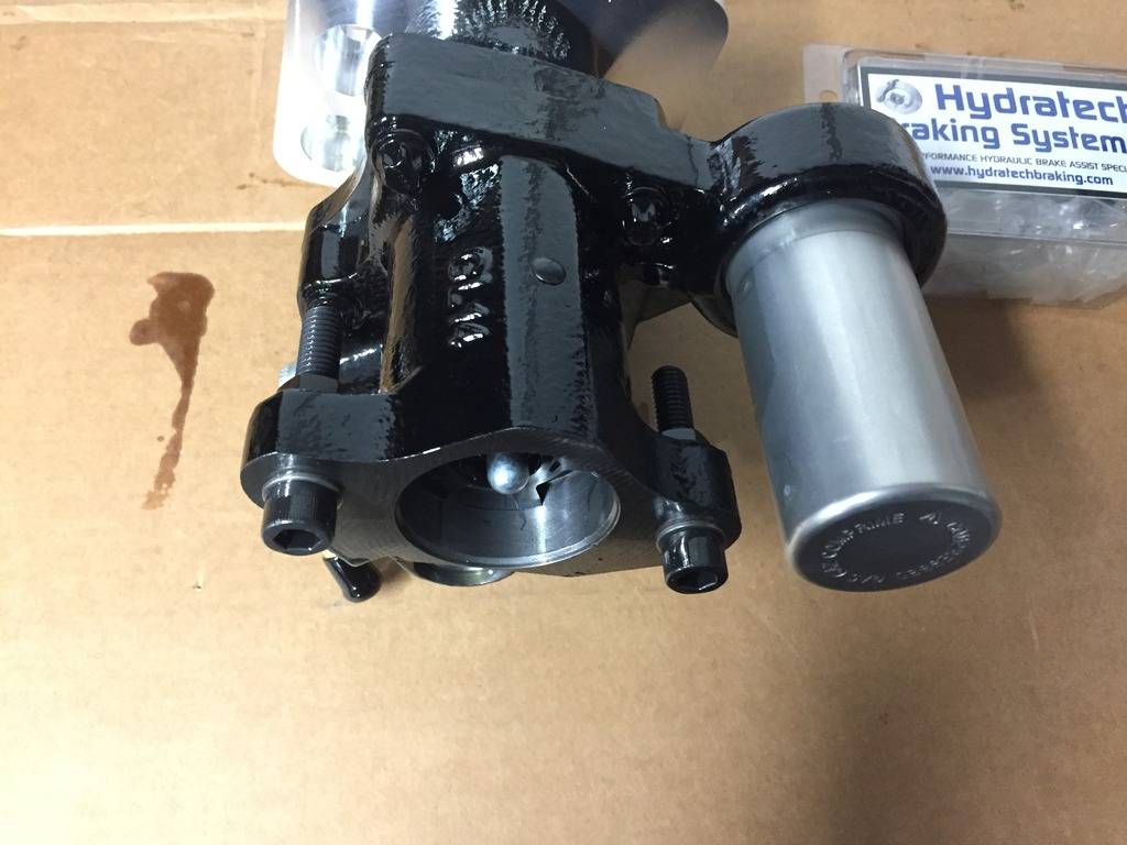
A couple of pics of the new Hydratech Hydroboost unit with the "Street" finish (mid grade):
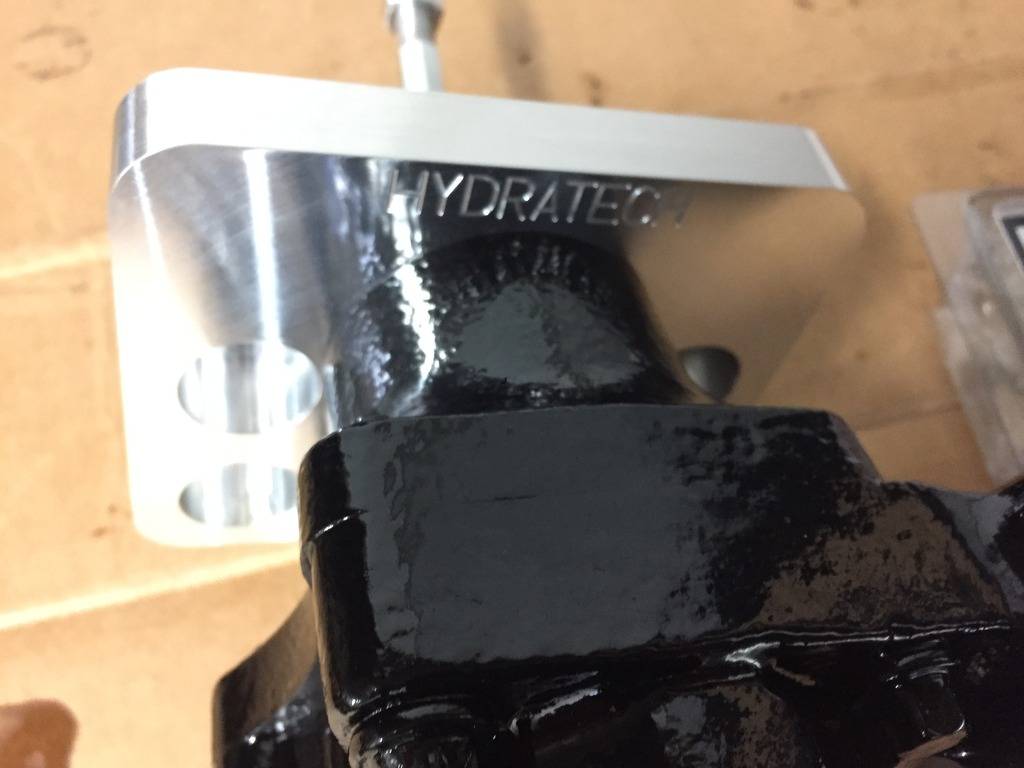
Old Master cylinder removed, and Hurst roll control pushed off to the side:
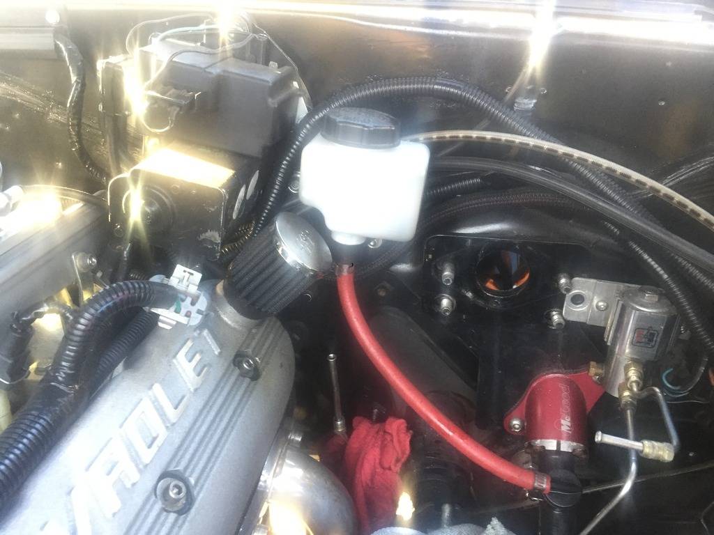
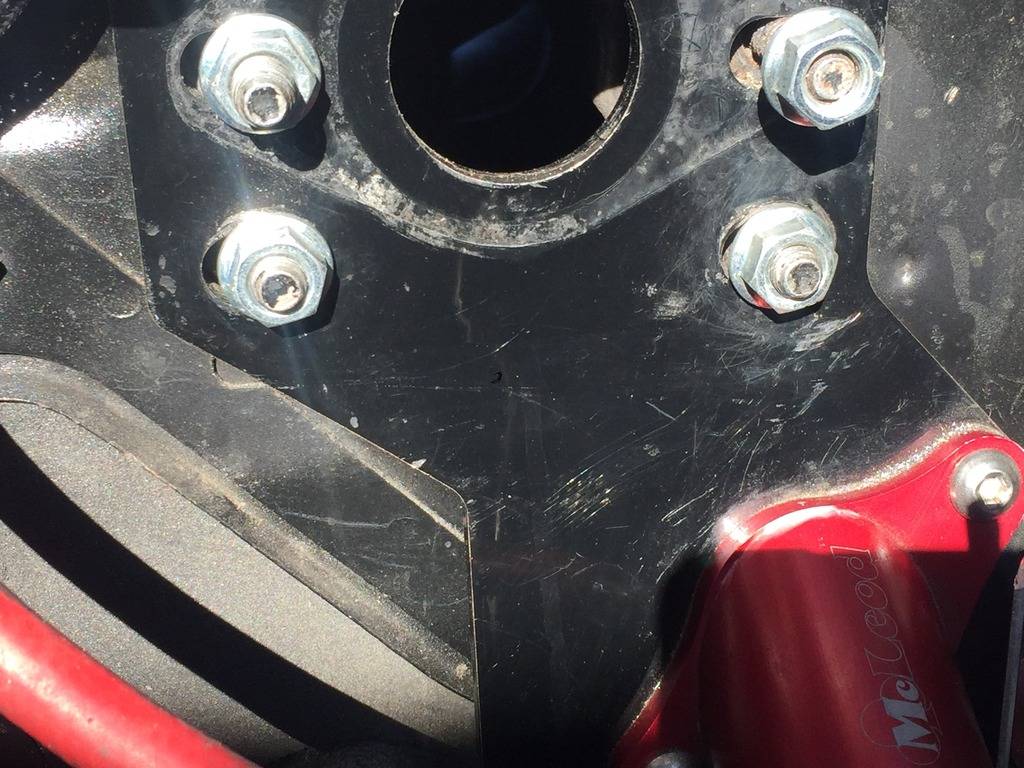
The first issue was that the aluminum base to the Hydratech unit hit the McLeod Clutch MC bracket. They share the same mounting bolts, but the McLeod bracket comes out at an angle just below the bolt holes. You can see the mark below the bottom right bolt where it hit.
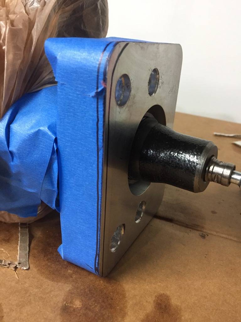
Here's what I planned to grind, and what I finally ground off. More than I needed, but there's still plenty of material left, the base to this unit is pretty beefy. I also bored out the mounting holes a bit. I don't know if their holes were off, or my mounting studs were off, but it was not an easy fit:
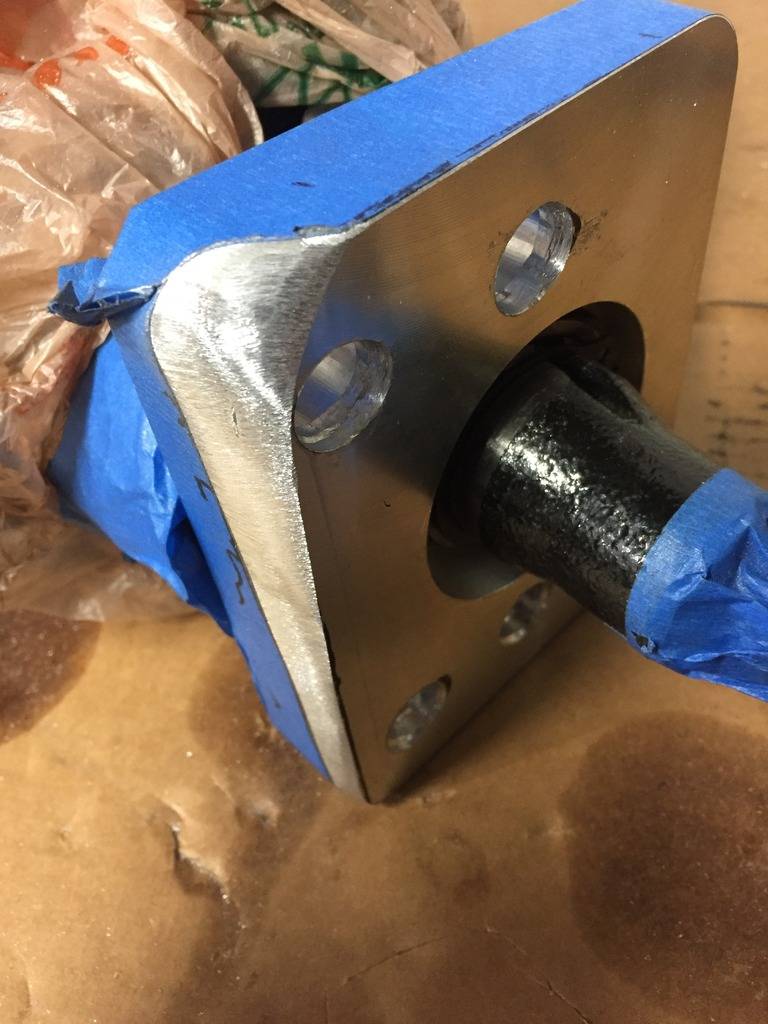
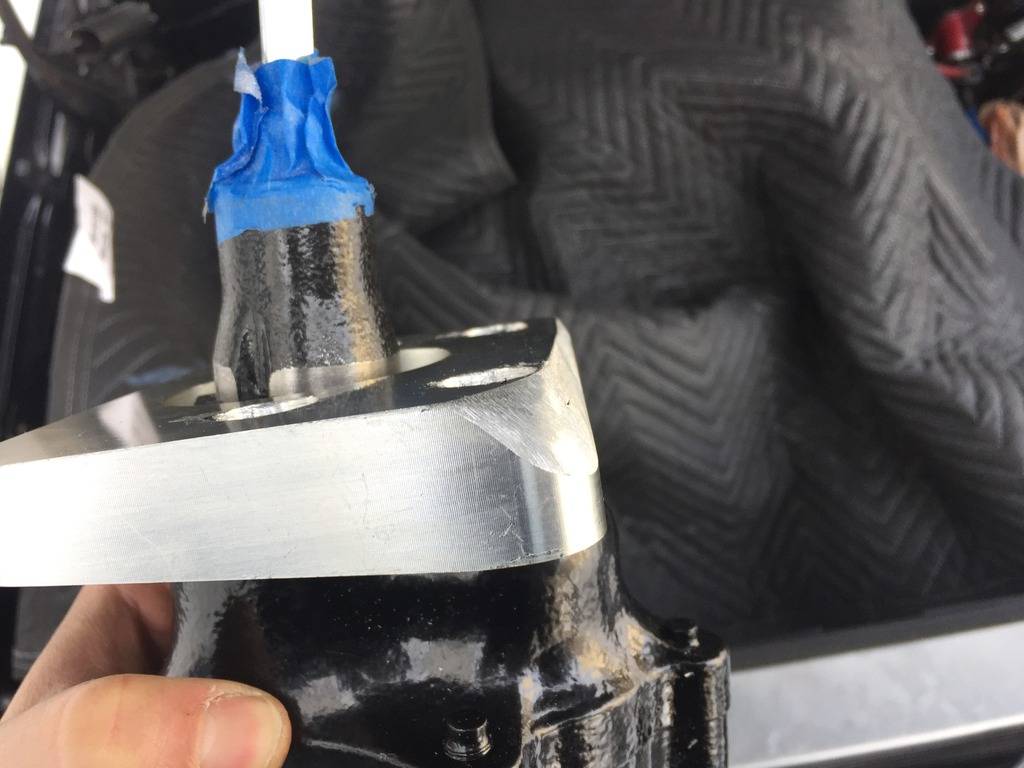
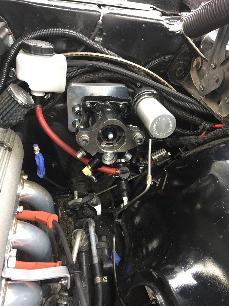
Finally got it fitted flush and bolted to the firewall:
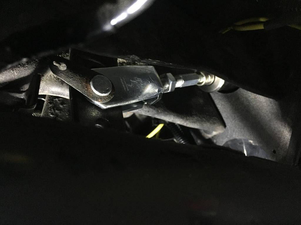
Not a very good pic, but this is the new clevis and rod that goes to the brake pedal. There are two mounting holes in the pedal, the bottom one is for power brakes, and the top one is for manual brakes. The instructions say to use the top one, but also state that the pedal rod needs to be as straight as possible. Off by more than 3 degrees will cause premature wear. The bottom hole was too low, and the top hole wouldn't even bolt up, and the angles were terrible. I ended up drilling a new 3/8" hole about half way between the old ones to get the rod dead straight:
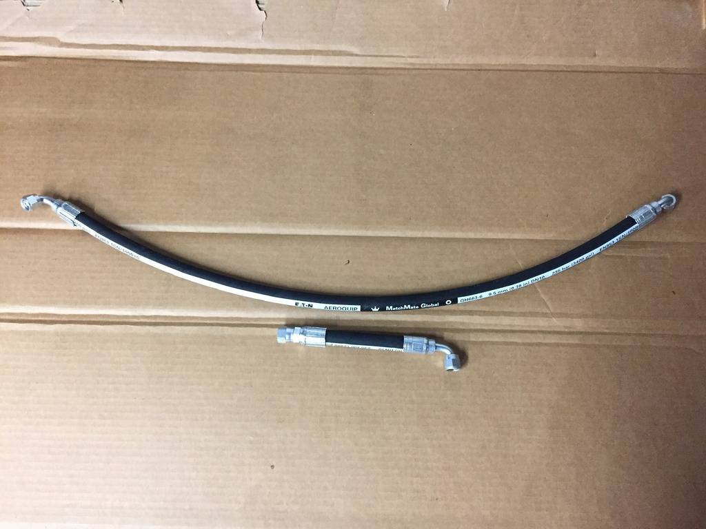
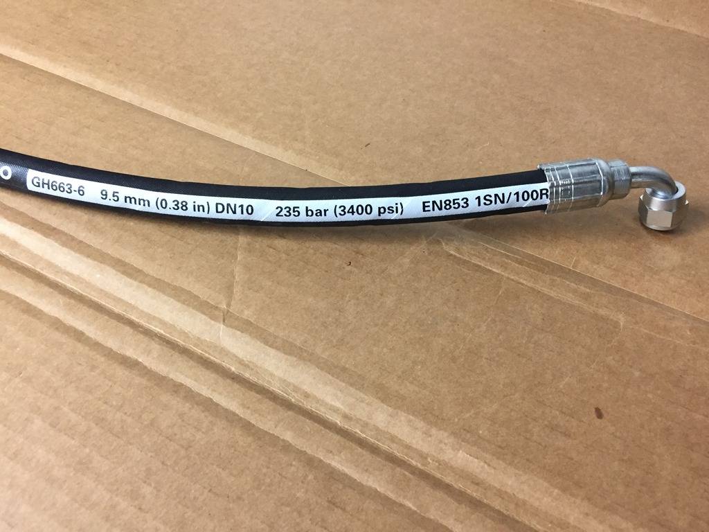
I had a couple of -6AN high pressure hoses made up at a local Hydraulic hose shop. I didn't want to play around with making my own, and didn't want the braided stainless look. The white stripe will be mounted facing down where possible. These hoses have an operating pressure of 3400psi, burst pressure of 13600 psi and operating temp of 260 degrees.
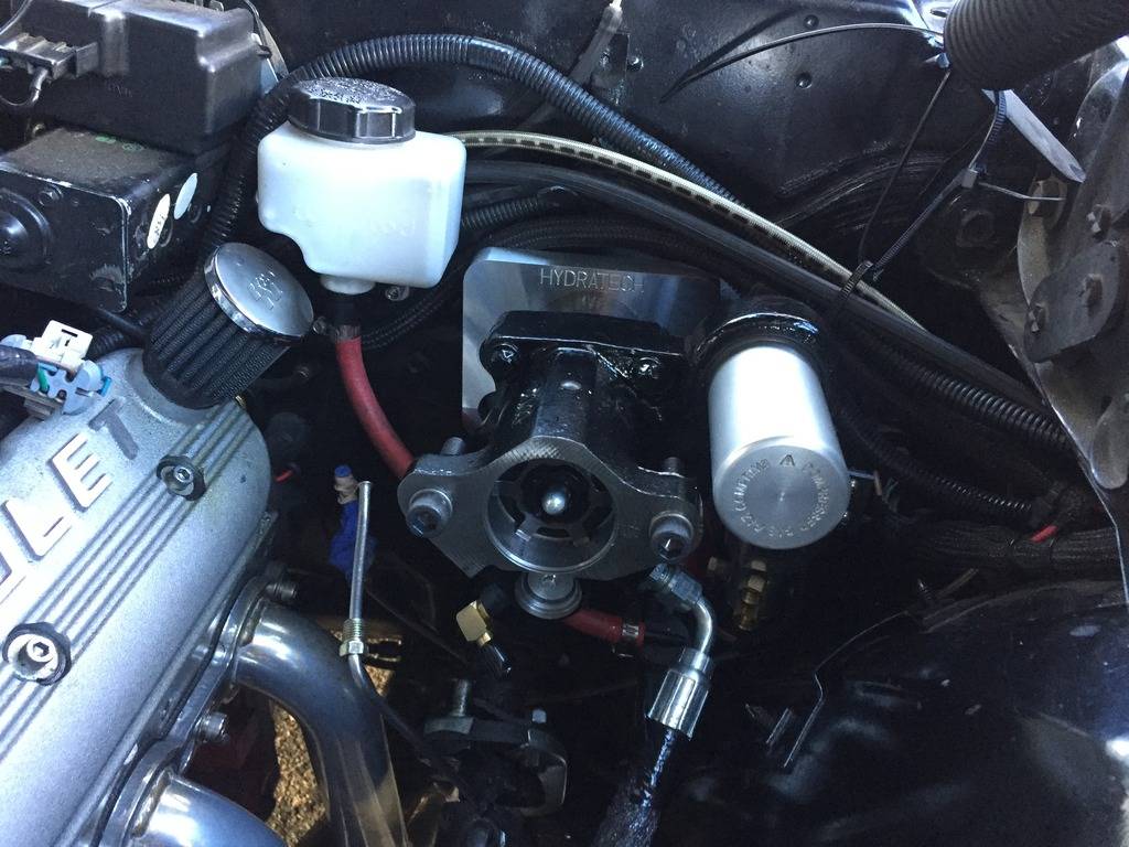
Another shot of the Hydratech unit with one of the hoses attached. Wrapped to keep the oil off it during install:
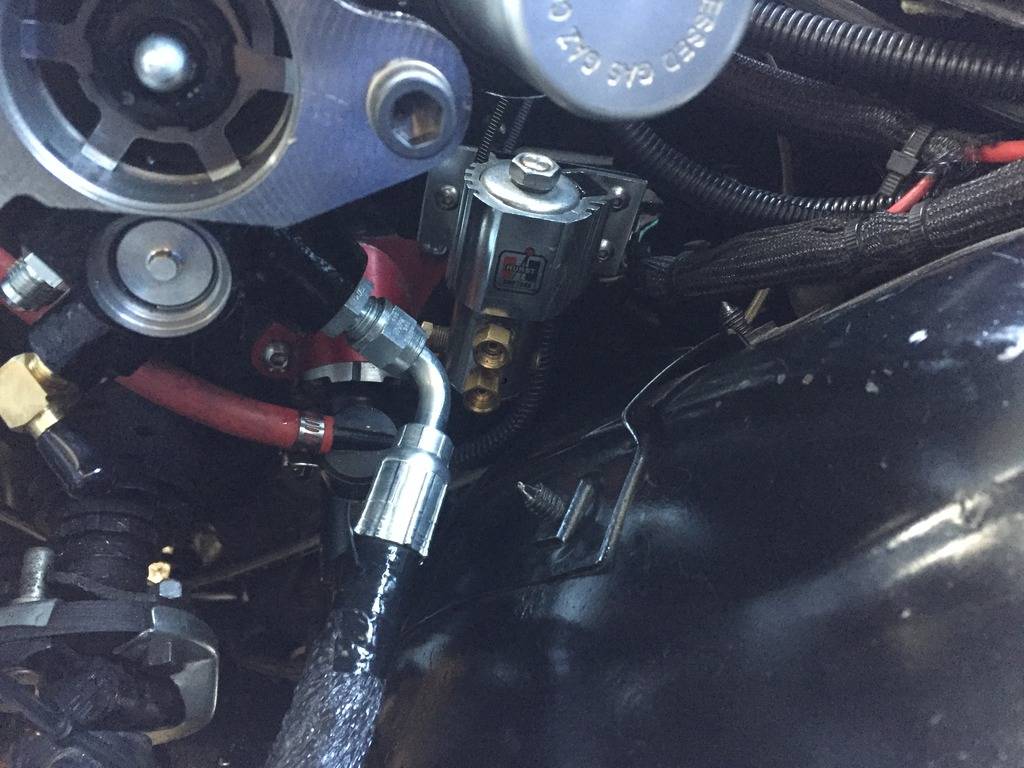
I had to relocate my roll control. It was mounted to the top right bolt hole, it wouldn't back in that location, so I moved it down to the bottom stud, then moved it over and out about an inch:
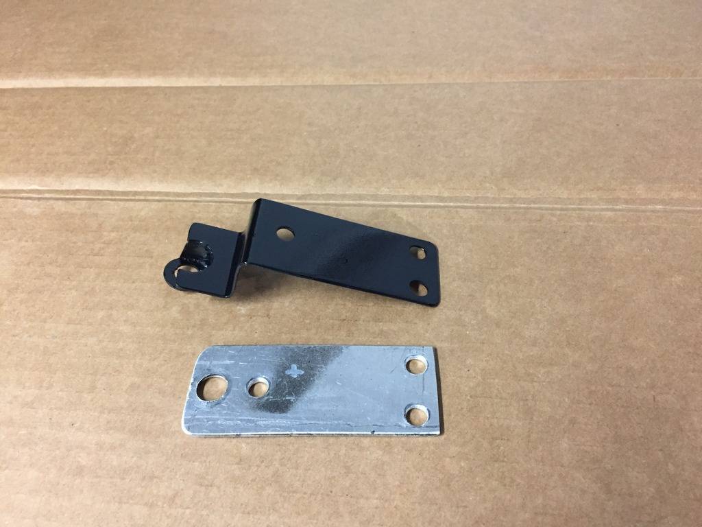
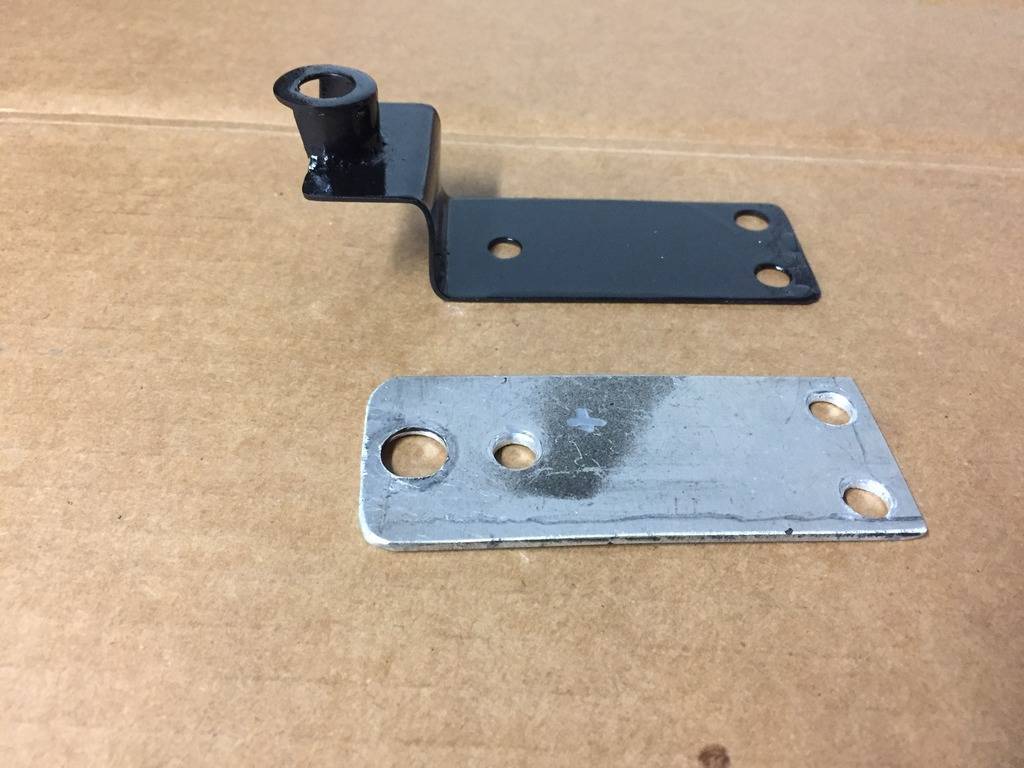
Here's my old roll control bracket in aluminum, and a new one that I fabricated out of heavy sheet metal and washer. The bolt holes on the Hydratech unit are recessed, so I needed to create something that would recess down the hole and could still get a long nut into:
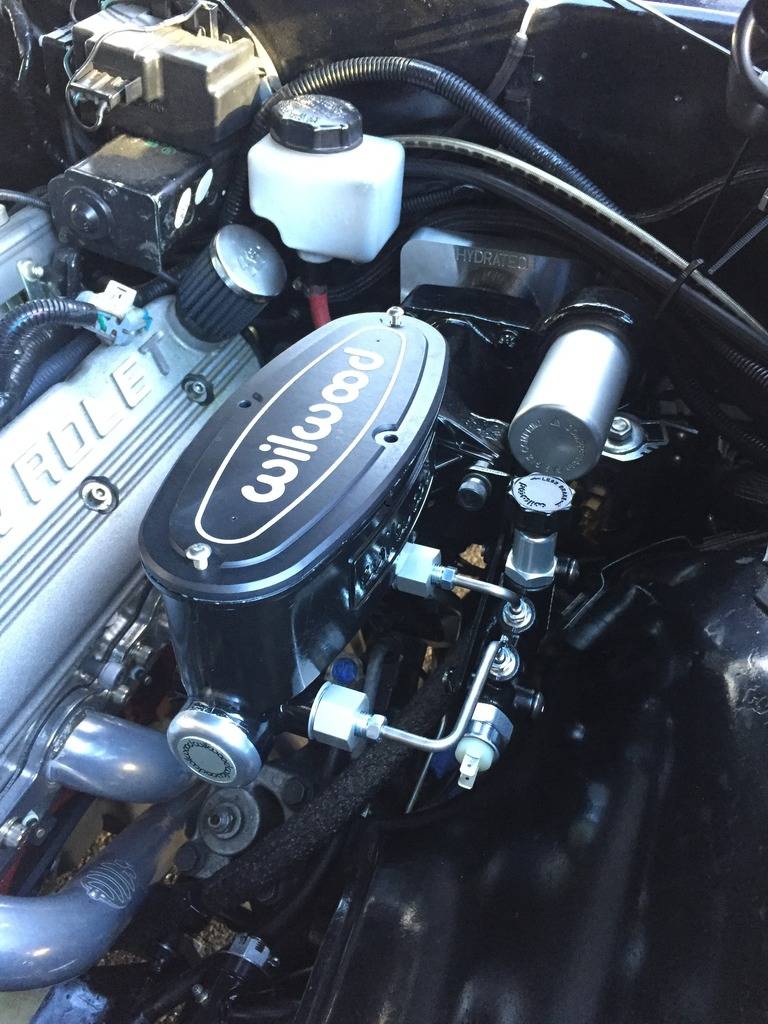
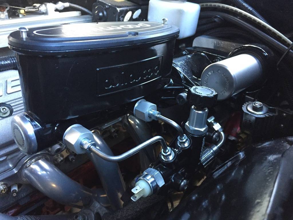
And this is where I left off today. New Wilwood Master (1 1/8" bore) mocked up with the new prop valve. I still have to bench bleed the MC, and run a few new brake lines.
-
02-24-2017 #525
Registered User
- Join Date
- Feb 2011
- Location
- dallas, tx
- Posts
- 1,731
with the hydratech unit i felt it was very tough getting the bottom lines to go to the wilwood bracket. I ended up using a art morrison bracketed that mounted the wilwood prop valve on its side. Also if you are using a brake switch on the pedal you will not need the switch on the prop valve. i thought it was a low fluid switch but its not. its a brake light switch. make sure you hook up your lines correctly on the hydroboost kit. 2 high pressure lines and 1 low pressure line goes to it.
-
02-24-2017 #526 Registered User
- Join Date
- Aug 2008
- Location
- jacksonville,fl
- Posts
- 972
One of the few luxuries my 83 el camino (originally diesel) came from the factory with that others have to work to get is hydroboost. You'll be glad you did it though. kinda gives you the feeling of having bigger brakes than you really have, within their actual limits of course.
02-25-2017 #527
Registered User
- Join Date
- Jan 2011
- Location
- Boston, MA
- Posts
- 1,180
Thanks, the prop valve is a little close to the inner fender, but it looks like there enough room to run the lines. I'll start at the prop valve and make my bends from there. I have a brake switch on the pedal, so the Wilwood one will come off the prop valve. I already had my hoses made up, so I know where they are going, and I replaced my PS pump with one made for Hydroboost, so I didn't have to T into the return line. Originally Posted by icemanrd19
02-25-2017 #528
Registered User
- Join Date
- Jan 2011
- Location
- Boston, MA
- Posts
- 1,180
Looking forward to power brakes! I think this upgrade along with the new 14"x1.25" rotors will make a huge difference. I can't fit any more brake into my 18" wheels, so this is as big as it gets! Originally Posted by jlcustomz
02-25-2017 #529 Registered User
- Join Date
- Aug 2007
- Location
- Jonesboro, Arkansas
- Posts
- 2,506
Out of curiosity, what is the advantage of the Hydroboost?
Carl Wilson
1968 Camaro - T-56 6 speed - 383 Stroker, 2014 Mustang GT seats. FiTech EFI, Tanks Inc. Tank with Deutschwerks fuel pump.
02-25-2017 #530
Registered User
- Join Date
- Jan 2011
- Location
- Boston, MA
- Posts
- 1,180
I don't have enough vacuum to run a traditional vacuum booster for power brakes. Hydroboost generates the power assist off hydraulic (power steering) pressure rather than vacuum. Originally Posted by minendrews68
02-26-2017 #531
Registered User
- Join Date
- Nov 2012
- Posts
- 5
[QUOTE=67rally;1221561]I only had one option in my adapter block. Maybe they changed the kit.
Appreciate the response. I definitely have some adjustment available. Pulling the bracket back out they added 3/16" up or down from center give you an option for different alignments. I also think my brake master studs are going to be short. I definitely don't have the length you have beyond the McLeod Bracket.
02-27-2017 #532
Registered User
- Join Date
- Jan 2011
- Location
- Boston, MA
- Posts
- 1,180
The top studs were long enough, I cut the lower ones and welded some longer studs back on. Originally Posted by starjunor
03-19-2017 #533
Registered User
- Join Date
- Jan 2011
- Location
- Boston, MA
- Posts
- 1,180
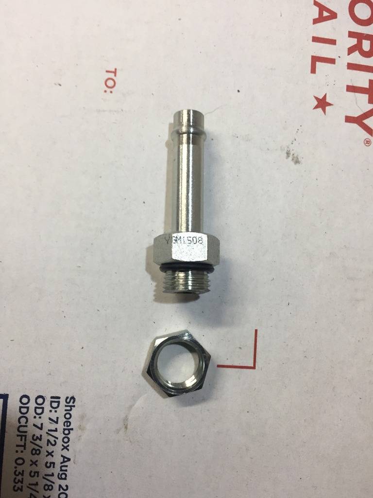
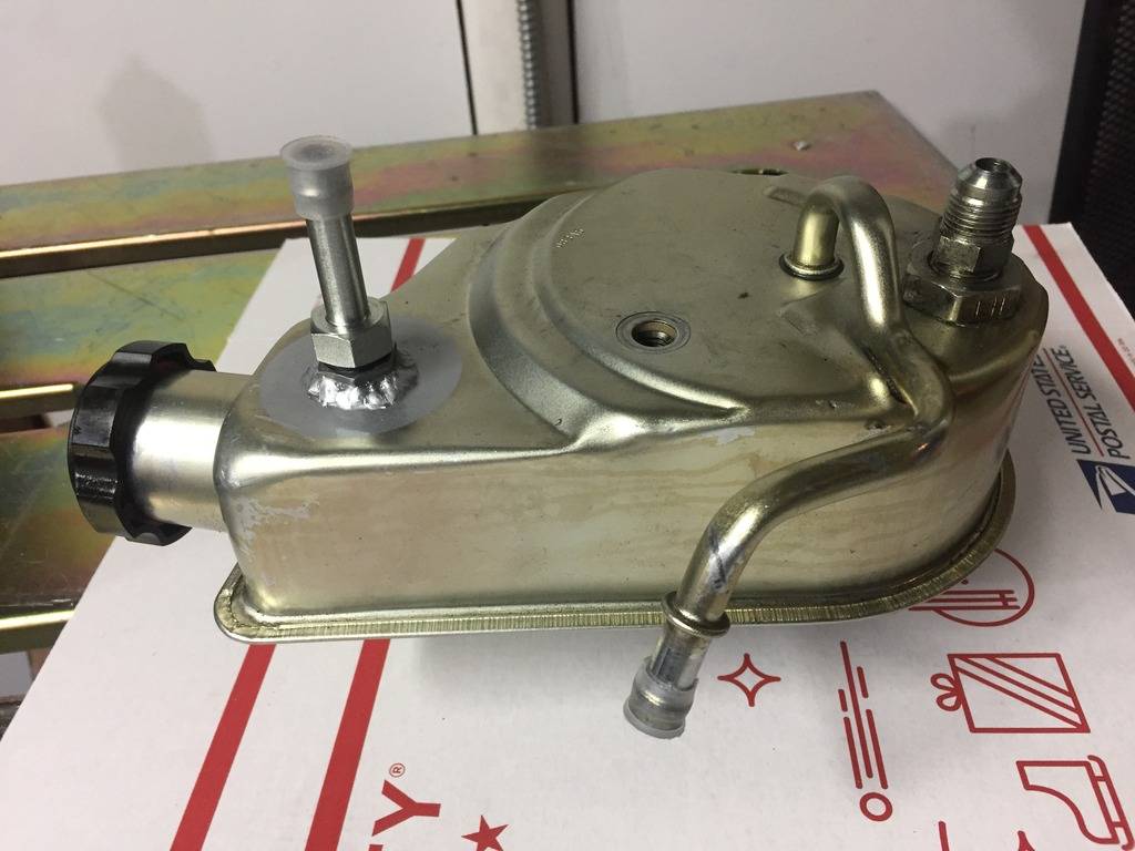
Adding a second return port to my PS pump:
Here it is with a single return down bottom:
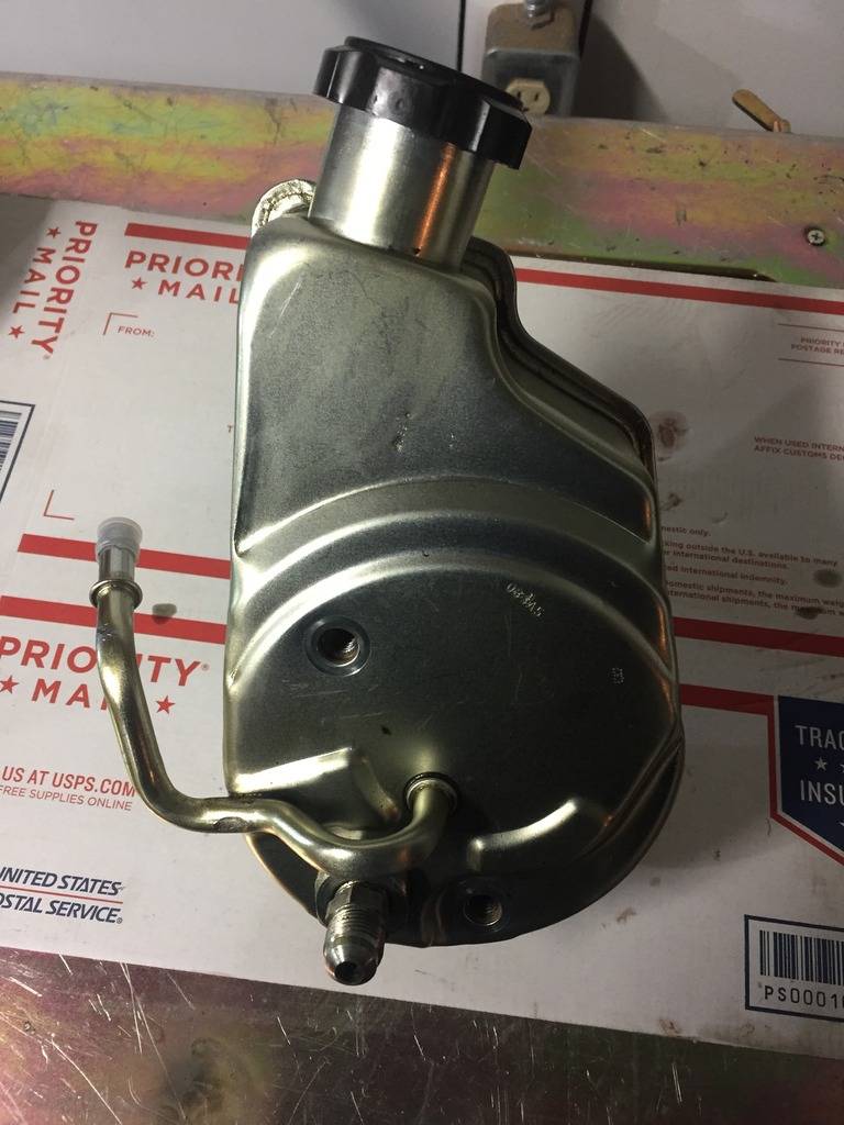
Here's the 3/8 o-ring port:
Mocked up:
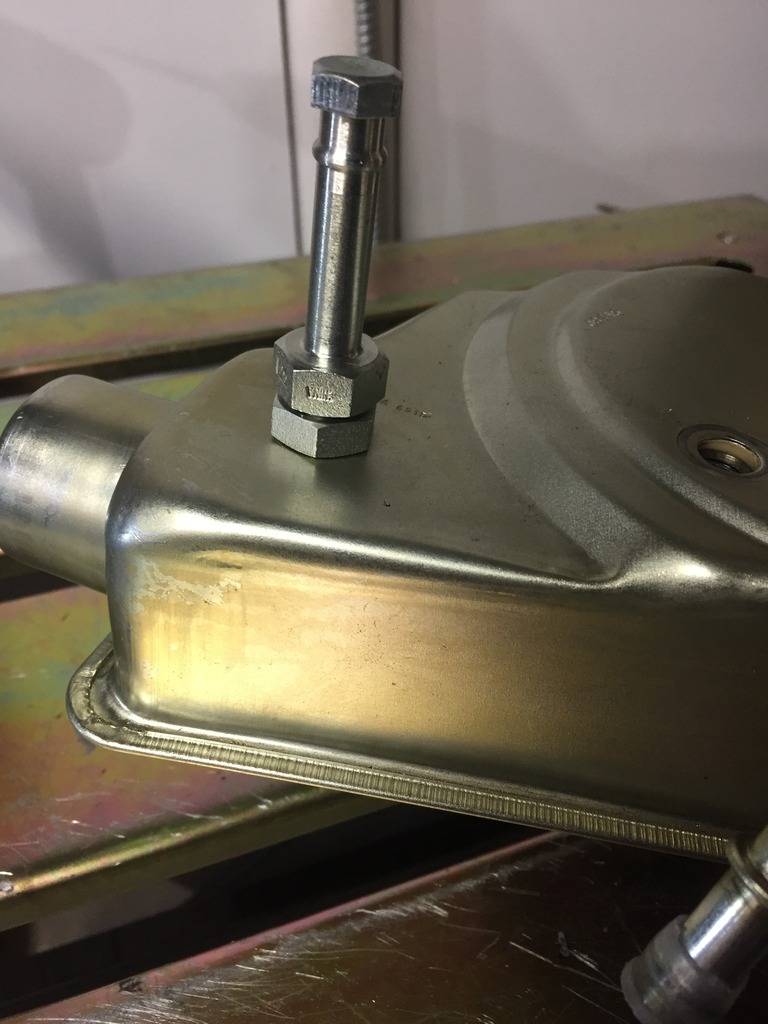
Welded up:
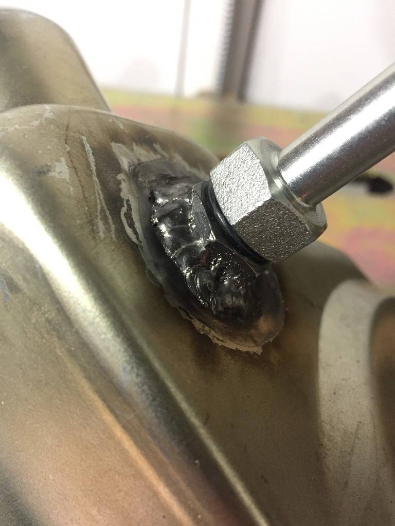
Painted. Yup, it doesn't match, I didn't have zinc colored paint, didn't want the welds to rust, and no one will ever see it anyways...
- - - Updated - - -
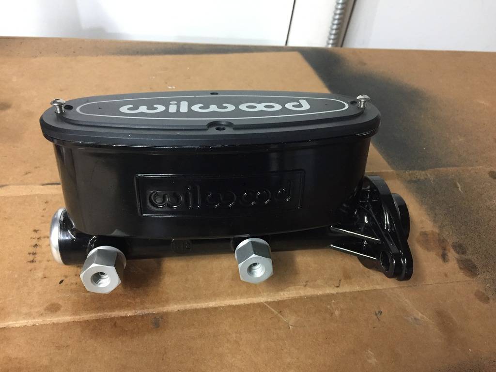
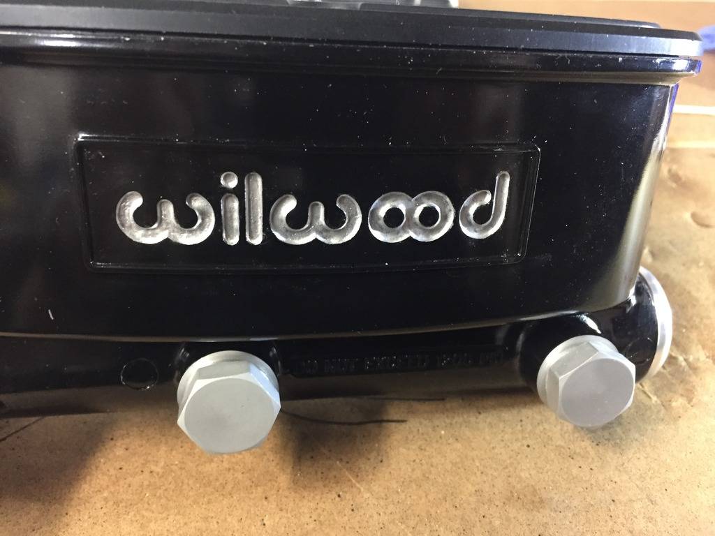
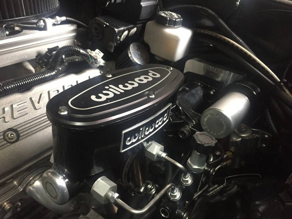
Wasn't real happy with the look of the new MC. My old one was raw aluminum with the black cover. On this one, I went with the black e-coat finish and I thought it looked a little bland:
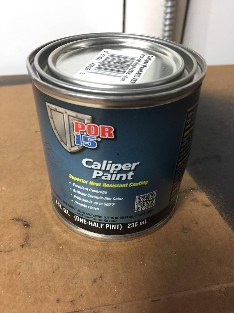
Picked up a small can of POR-15 silver caliper paint:
Painted the recessed Wilwood logo silver:
Thought it needed more, so I masked off the raised rectangle:
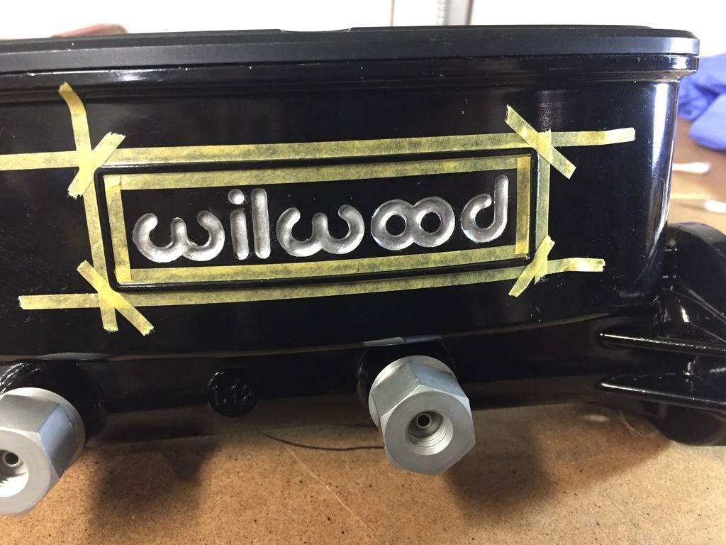
And gave that a quick coat as well:
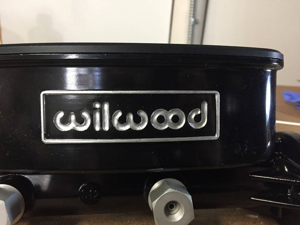
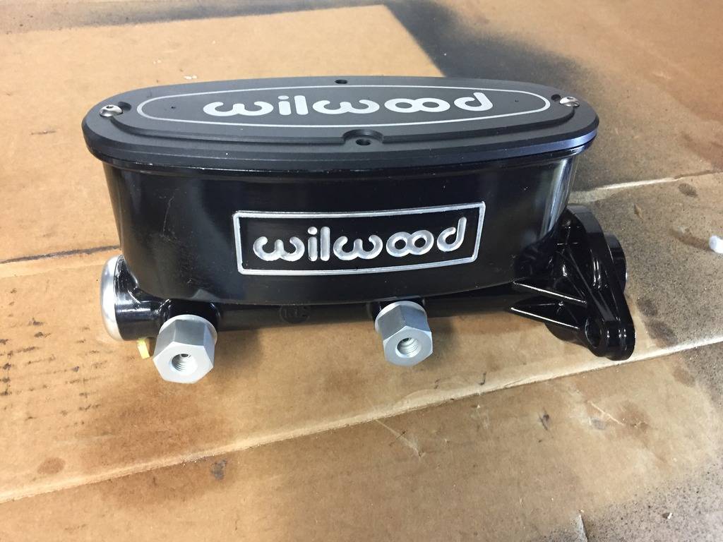
It's a small detail, but I like this look much better. I'll clean up the little imperfections before it goes back on the car:
- - - Updated - - -
MC/Prop Valve/Hydroboost installed, all brake lines hooked up, PS hoses are run, just need to trim to length once I know the exact routing around other components:
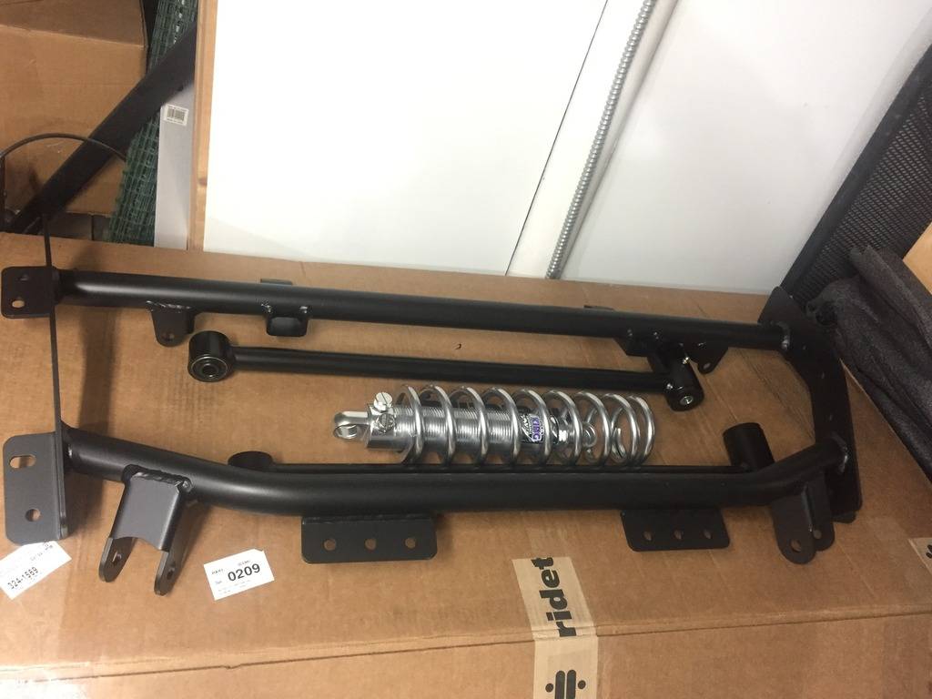
I pulled the RideTech 4 link and Viking Coilovers out of their boxes, but will wait for a nice warm weekend to begin the install.
03-19-2017 #534
Registered User
- Join Date
- Jan 2011
- Location
- Boston, MA
- Posts
- 1,180
2 steps forward, one step back...
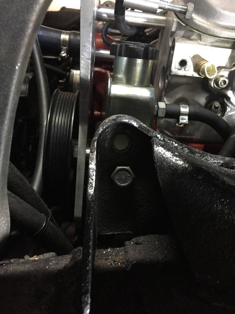
I ended up removing the drivers side SpeedTech UCA. When I did the Guldstrand Mod, it moved the drivers side arm back and down enough so it was hitting the ear that the control arm bolts to. I ground the ear down a little, but it wasn't enough, so I removed the bushings from the control arm, ground some off, and shimmed it to move the arm forward. Unfortunately my drivers side control arm would have been slightly forward of my passenger side. It wasn't really the right approach, so I called Blake from Speedtech and explained my stupidity, and he's going to hook me up with a couple new bushings. Stand up guy, I screwed up, and he takes care of it!
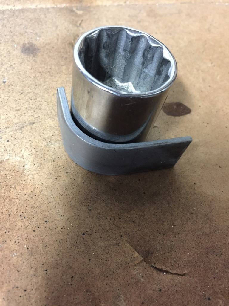
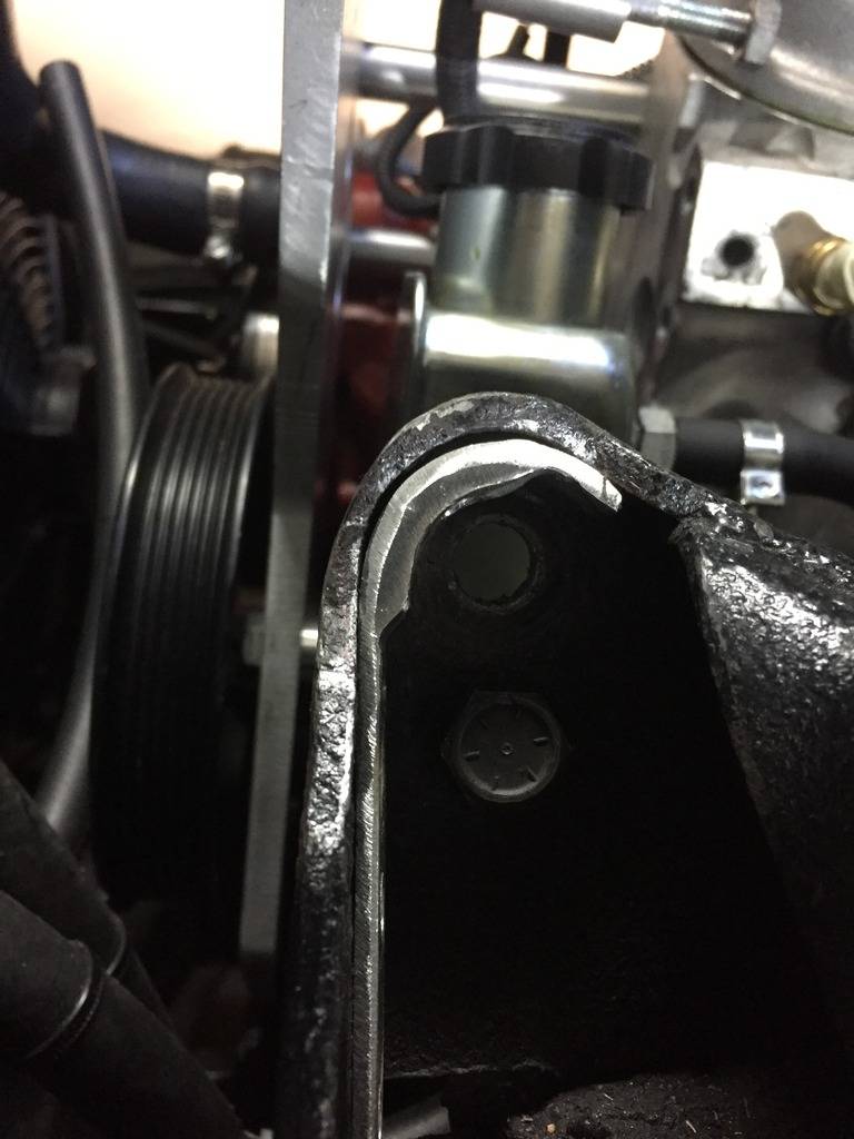
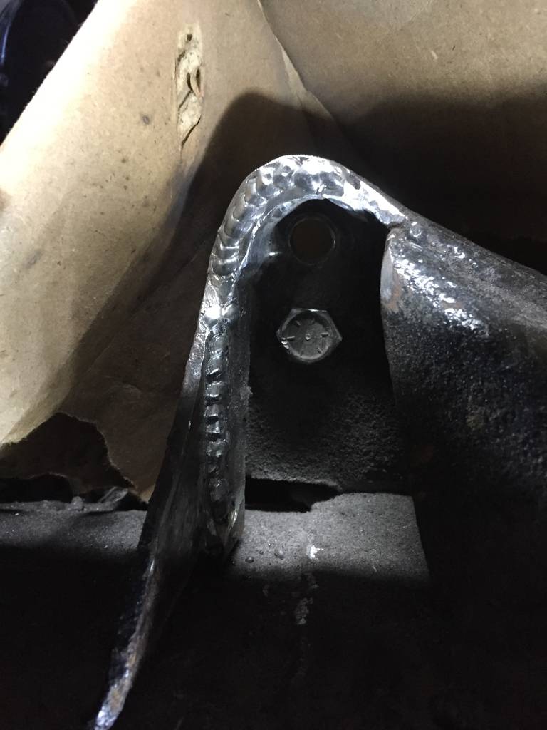
So I shipped my bushings off the Speedtech, so they could replace with identical ones (they've changed the design slightly a few times and he wanted to make sure I got the right ones). Then I added some material to the mounting ear, so I can grind it back without compromising the structure. I used some 1/8" steel stock, bent it around a socket with the right radius, drilled some holes so I could plug weld it, and welded it back up. I'll grind the ear back once I mock up the control arm to make sure I have plenty of clearance. I'll smooth the welds and give it a fresh coat of paint so it kind of blends back in.
Here's the ear in question, you can see where I started to grind the top left area. To get the clearance I needed, I would have gone completely through the structure:
Test bending some steel stock:
Added a small second section where the majority of grinding will take place:
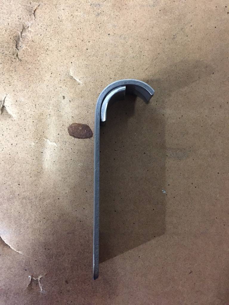
New piece:
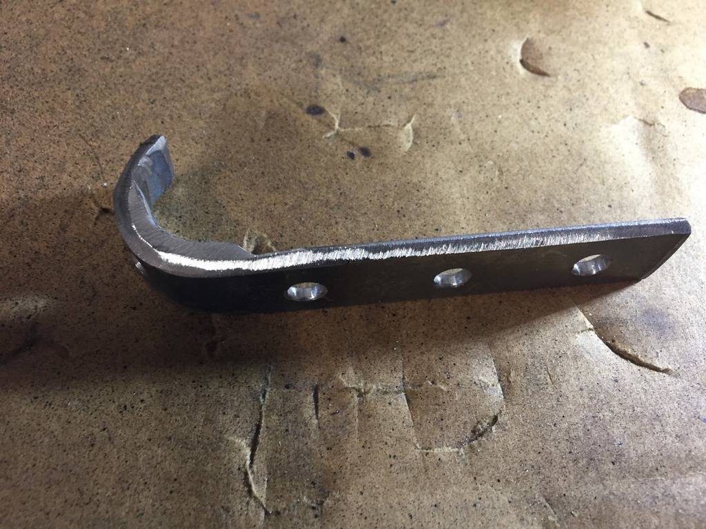
Mocked up (I beveled the inside edge for better weld penetration):
Welded up, lots more material to work with:
03-19-2017 #535
Registered User
- Join Date
- Jan 2011
- Location
- Boston, MA
- Posts
- 1,180
I also just put an order in for a set of DSE Mini Tubs. Wheels and Tires will have to wait for a while, but I might as well do the tubs when I pull the rear supsension apart.
03-23-2017 #536
Registered User
- Join Date
- Jan 2011
- Location
- Boston, MA
- Posts
- 1,180
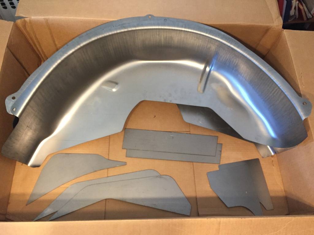
Minitubs and frame rail closeouts have arrived. Unfortunately these are going to sit in a box for a while. I won't be able to do the 4 link and tubs until mid/late April.
04-21-2017 #537
Registered User
- Join Date
- Jan 2011
- Location
- Boston, MA
- Posts
- 1,180
A few more updates...
Fuel tank is out:
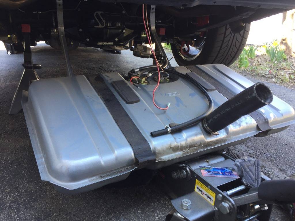
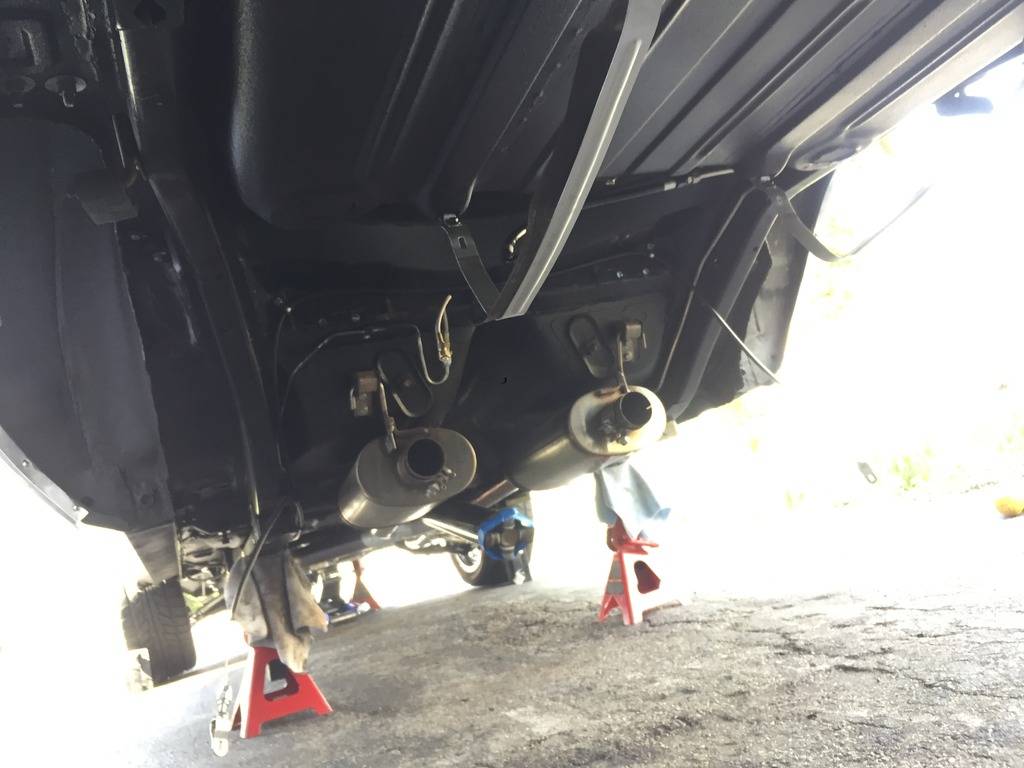
I removed the shocks and e-brake cables, disconnected the rear brake line, dropped the leaf springs and rear end out today and removed the tail pipes.
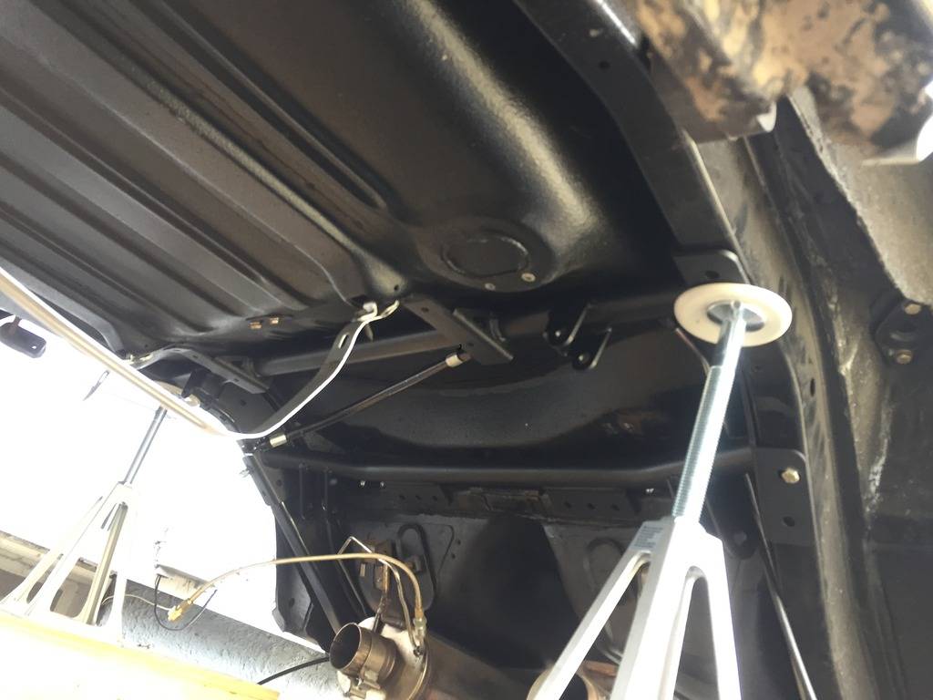
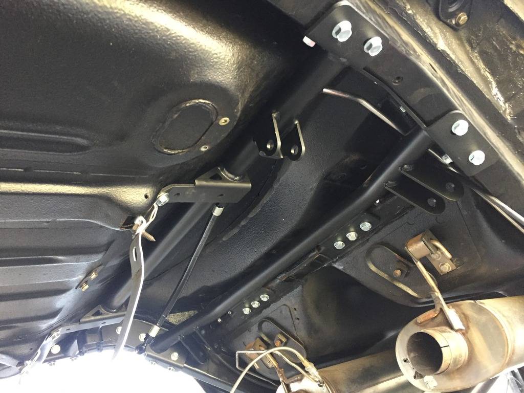
Test fitted the ridetech "cradle" for lack of a better term. These little adjustable jack stands really came into handy doing it by myself. I had to hammer on my frame rails a little, not ridetech's fault. When the Hotchkis rear sway bar bracket got bent, it pulled the bolt holes in the frame rails inwards slightly and the RideTech bracket would not fit flush to the frame rails. I hammered the bent area flat, mocked the cradle back up, and started drilling the holes to attach it. I'll finish that up early tomorrow, get the rear end back in place, centered, set pinion angle and then tack up the 4 link tabs. It's supposed to be a little windy here, so I'll move the rear end back into the garage to final weld it.
Finished drilling and bolting in the new 4 link bracket:
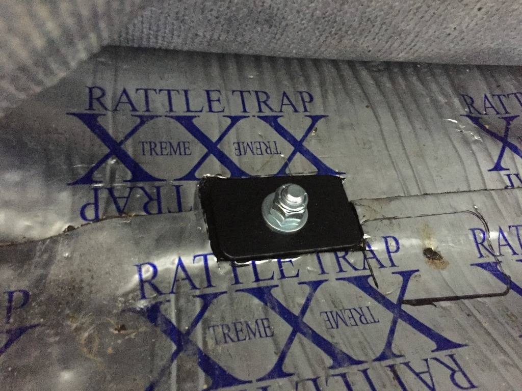
Reinforcement plates in the trunk:
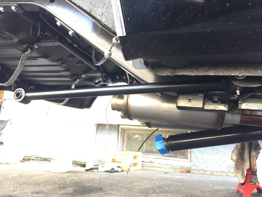
Lower 4 Link arms bolt in place of the leaf springs:
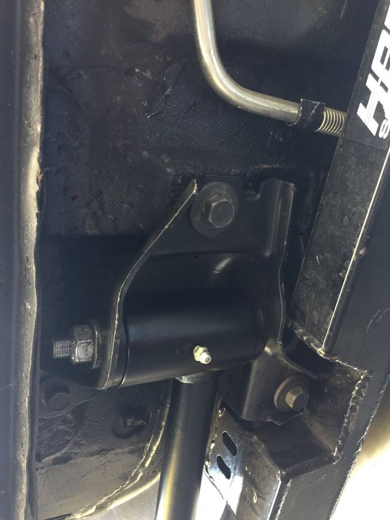
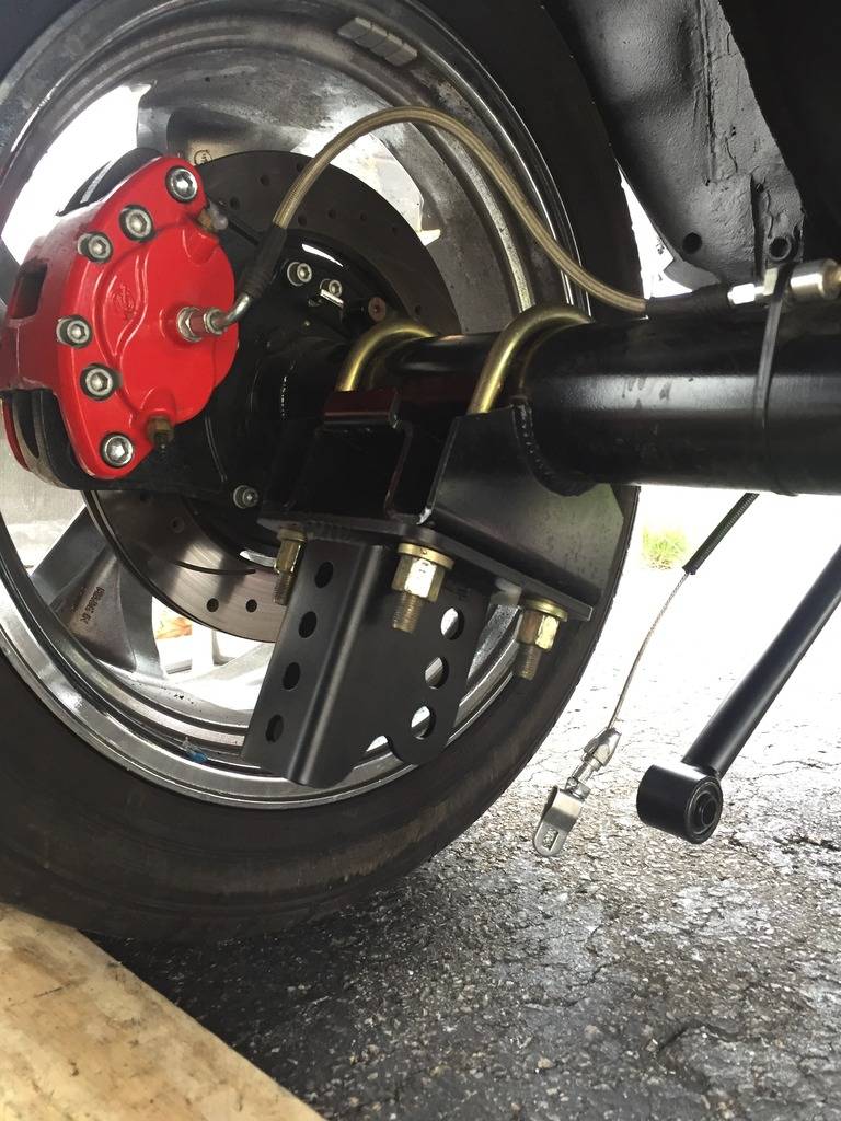
New bracket mounts to the leaf spring perch. Forward holes are for the 4 link bracket, rear holes are for the coilovers:
04-21-2017 #538
Registered User
- Join Date
- Jan 2011
- Location
- Boston, MA
- Posts
- 1,180
Got the axle centered and at ride height, pinion angle set at 3 degrees up. The engine/trans is at 3 degrees down and ridetech recommends equal but opposite angles. No axle wrap with a 4 link so no need to drop the pinion angle down from there.
I cut a couple pieces of bar stock and drilled holes at 14.5" on center to replicate the shocks. This makes it easy to adjust the pinion angle without shifting the axle up or down:
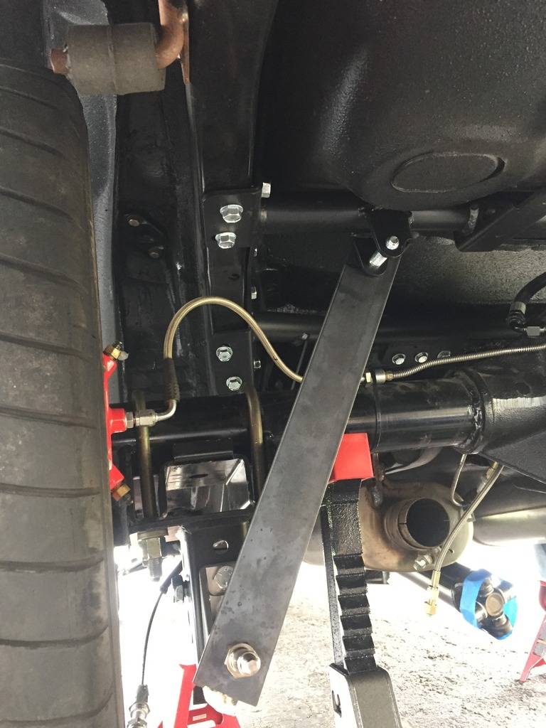
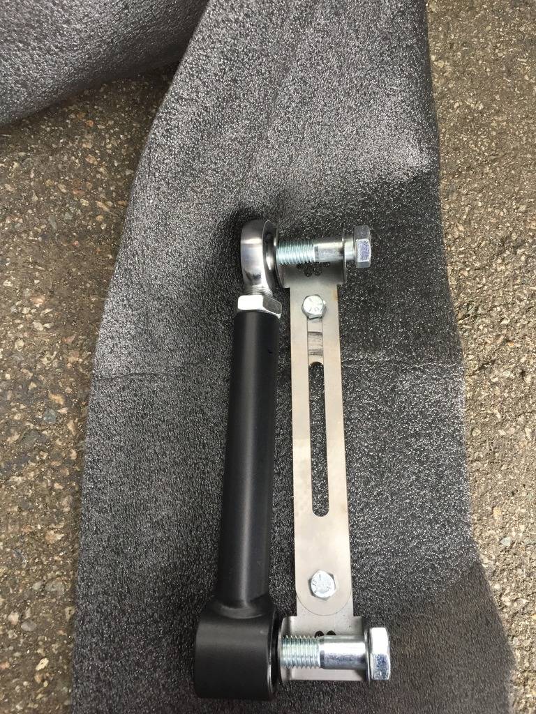
ridetech supplies this little jig (right) to replicate the upper arm (left) so you don't fry the bushings while welding:
Upper arm mounting tabs mocked up. They didn't fit the contour of the axle (notice the tab furthest away, the tail hangs out quite a bit). I've read that this is a common problem:
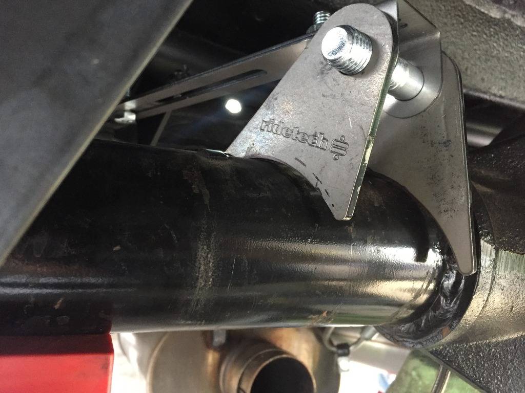
A few minutes with a grinder and they fit a lot better:
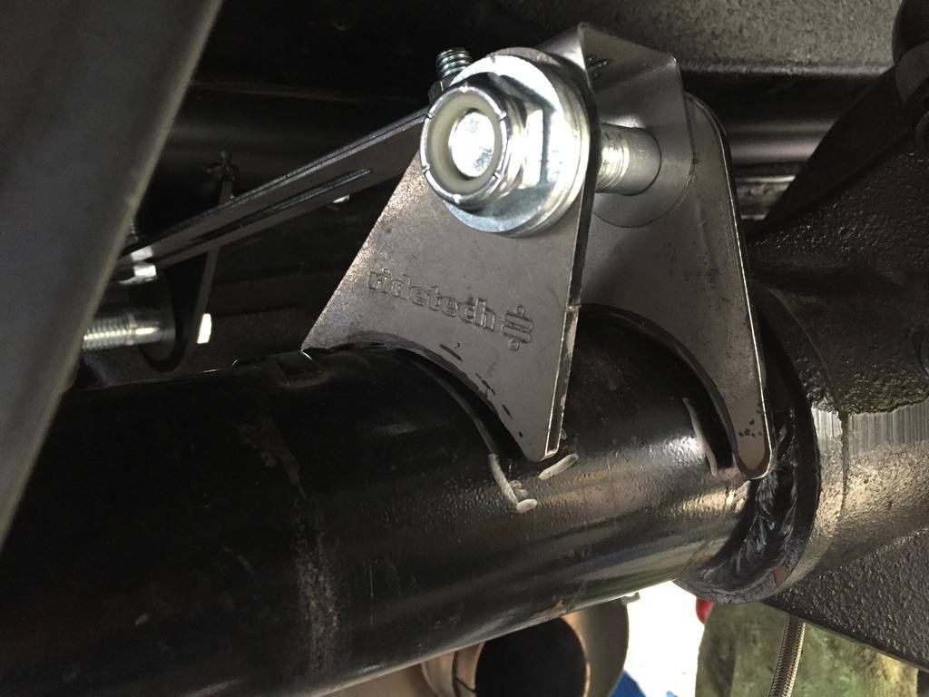
Tabs tack welded in place:
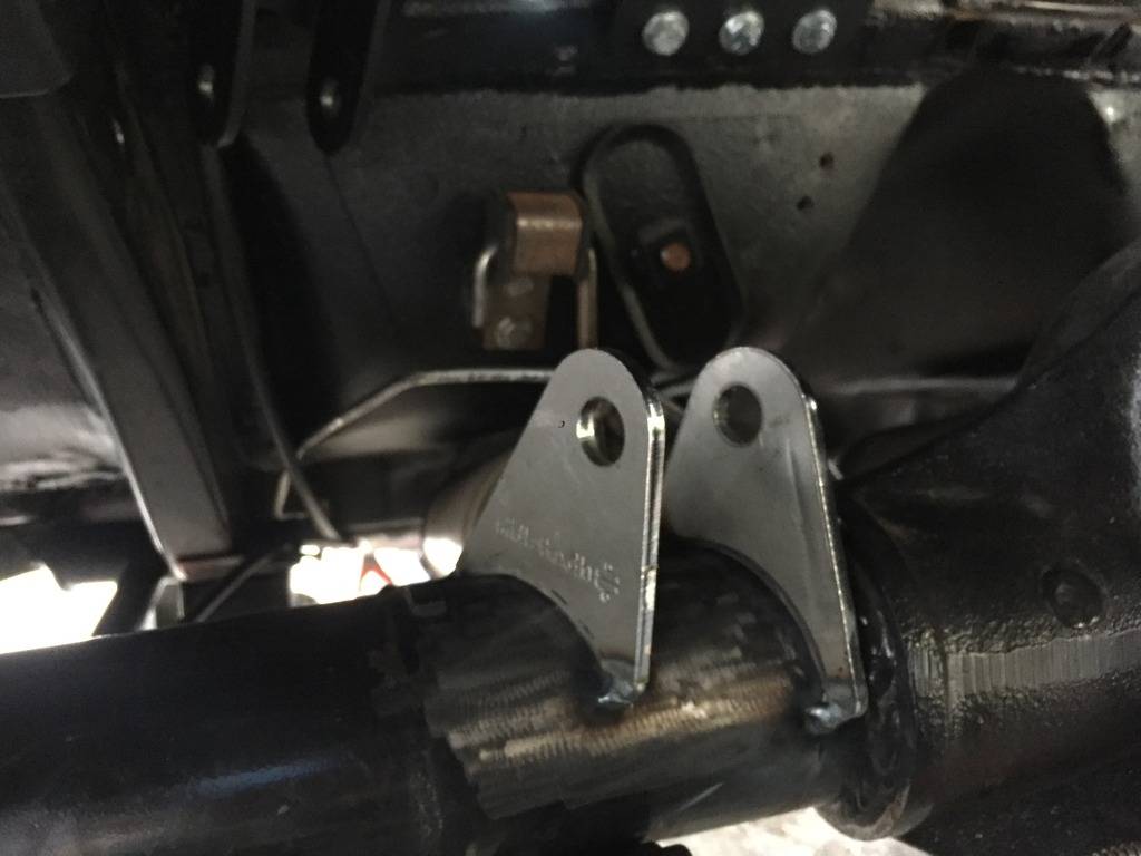
I tacked the drivers side in perfectly, then tacked the passenger side in. The instructions say to re-measure pinion angle, which I did and realized that the jack I was using to hold the pinion had dropped out. I ended up tacking in the drivers side at 3 degrees up and the passenger side at 3 degrees down. I had to grind out the welds and start over.
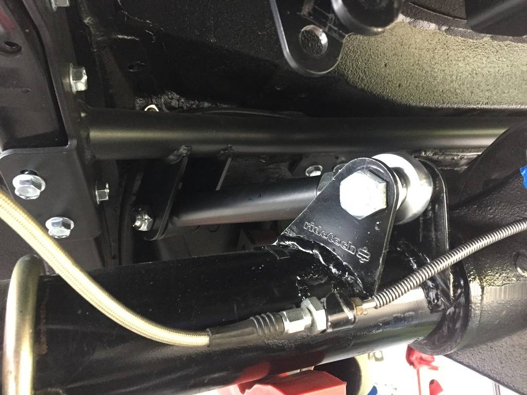
Tabs welded up, and repainted. I added a brake line holder while I was at it.
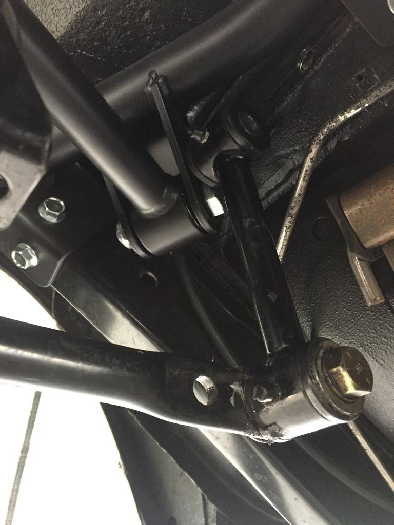
I tried refitting my Hotchkis sway bar, but it's not going to work:
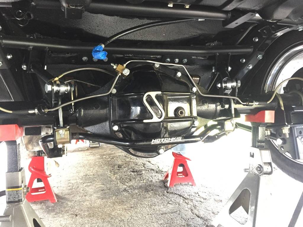
The sway bar end links want to occupy the same space are the RideTech upper arms:
- - - Updated - - -
I ended up replacing my fuel sender while the tank was out. I was tired of the gas needle bouncing around with the old float design.
Classic Instruments sells an enclosed, tube style sender that eliminates the needle bounce. Part number SN38T6 (6") for the regular Tanks Inc tank, or SN38T7 (7") for the deeper notched tank.
Of course the holes were slightly off, so I had to bore them out on the new sender with the next size drill bit.
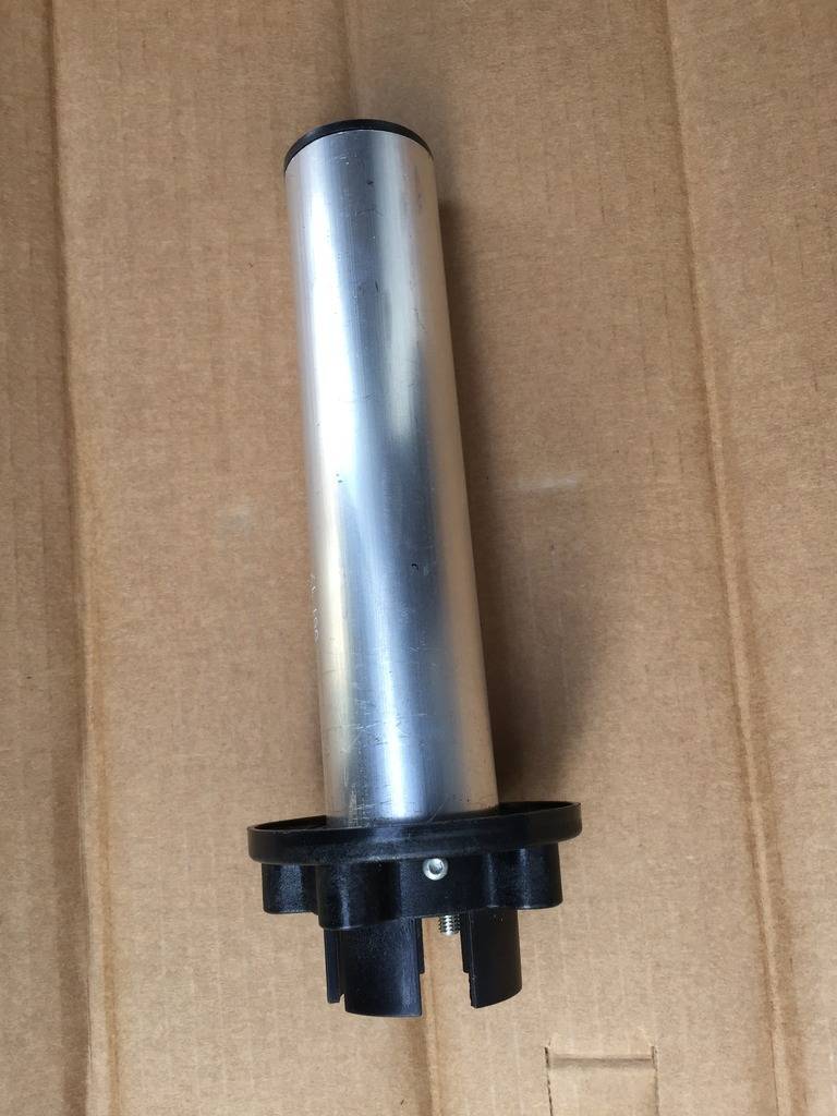
Old:
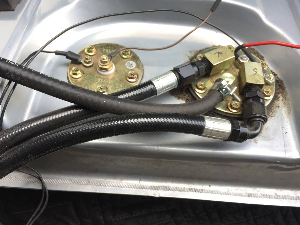
New:
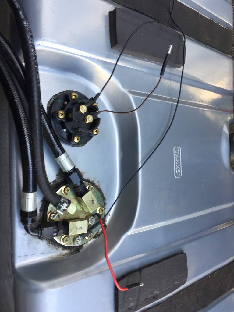
04-22-2017 #539
Registered User
- Join Date
- Jan 2011
- Location
- Boston, MA
- Posts
- 1,180
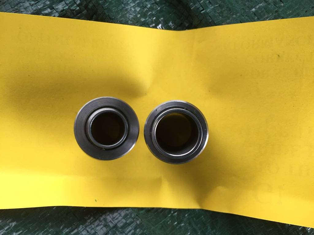
1/2" vs 5/8" bearings from Viking. The bottom shock stud is 5/8". While the top mounting bolt is 1/2". Viking supplies a 1/2" sleeve with the 5/8" bearing, so I installed the 5/8" in the lower and upper, and then used the sleeve in the upper.
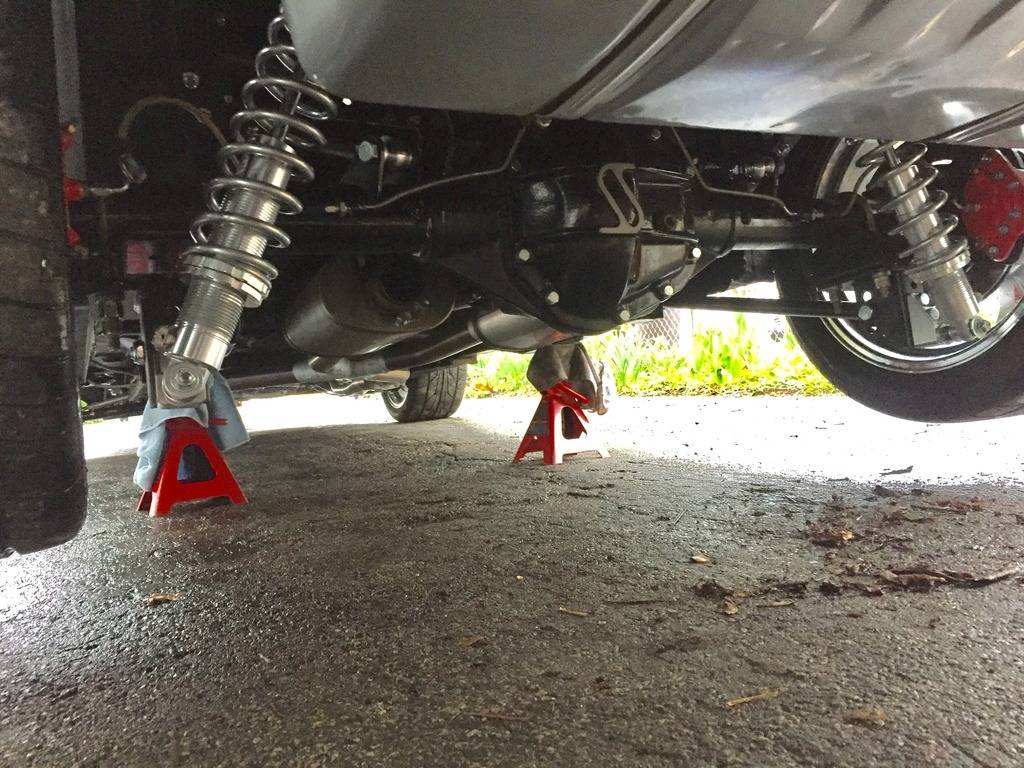
This is the top of the shock. The only drama today was this gap (at the right in photo) between the top shock bearing and the mounting tabs. I used a 1/2" grade 8 washer so there wouldn't be any slop:

Got everything buttoned back up and back on the ground, brakes bled, and was able to drive back into the garage under its own power.
04-23-2017 #540
Registered User
- Join Date
- May 2015
- Posts
- 254
Nice work!


 Reply With Quote





