

Results 101 to 120 of 132
-
01-26-2017 #101

 Starting The Transformation
- Join Date
- Feb 2010
- Location
- El Segundo, CA
- Posts
- 268

I've spent a few days doing a few things to try to remedy a brake pad knock back issue I've been having. The issue started when I upgraded my brake system a while back. My intention was to go with manual brakes, as I'm of the opinion that it leads to better brake feel. Although that may be true, the tight confines of a truck can make it difficult to position the brake pedal far enough away from the driver to get good leverage. As a result pushing a manual pedal is not easy. I had thought I could get around this by implementing large diameter brake rotors, as the pads would have more torque on the rotor, leading to increased stoping power and hence less pedal effort. At first I ran racing pads with a high cold friction coefficient, and with those pads my theory worked pretty good. Super stiff pedal with good stopping power and great brake feel. But the racing pads squealed like crazy, not to mention the cubic feet of brake dust they pumped out, so I was forced to switch to street pads. The stopping power was then reduced, forcing me to decrease master cylinder sizes in order to reduce pedal effort to a manageable level.
Anyone who's up to speed on knockback can see where this is going. Knockback is made worse by (a) large diameter rotors and (b) small master cylinder sizes. Large diameter rotors just exaggerate the distance that the rotor moves to push on the pads when stuff in the hub area flexes while cornering. Small master cylinders are more sensitive to the caliper pistons being pushed away from the rotors simply due to the smaller brake fluid volume they contain. I have a few "chicane" type corners in my neighborhood that, while low in speed, are high in cornering force. I would definitely notice the pedal moving way too far at the stop sign following these corners. No need to even to go the track in order to ascertain I had a knockback problem.
I figured the first thing I should try was to install some anti-knockback springs in the calipers. I ordered the appropriate Wilwood springs and proceeded to remove the brake calipers and pop out the pistons to install the springs. I go to pop out the first piston with 40 psi of compressed air and WTF? There was already a spring in the piston bore! I checked a few more pistons on different calipers and they all had knock back springs already installed (from the factory). I guess the calipers I bought (black anodized instead of powder coated) are considered "race" calipers and come with the springs pre-installed. Apparently they are of limited effectiveness. When I re-installed the caliper pistons I saw why. The Wilwood springs are not strong enough to overcome the stiction in the piston seals. If you push the piston all the way in to the bore, it just sits there. The spring does not push it back out.
OK, I had to think about this a bit. It's possible that when braking, that the caliper pistons do not actually slide through the seals, but rather that their motion is small enough that they just 'flex' the seals. If this is true then the relatively weak Wilwood knockback springs would still help. But if knockback were bad enough to move the pistons relative to the seals, then these springs would not do much. Wilwood is pretty good about providing information regarding their products (one reason I like them). The packages that the knockback springs came in listed the minor and major diameters of the springs as well as the spring rates. And the rates are in the 3 lbs/in range, which is not huge. Performance Friction springs are around 7 lbs/in and AP Racing makes knockback springs up to 12 lbs/in. So I went to McMaster-Carr and found conical springs that fit the bill - same size but about twice the spring rate. I bought some and set about installing them. I've not yet driven with them (hopefully tomorrow). I only installed the stronger springs on the rear calipers for now, since this is where I suspect most of the flex is coming from that is inducing the knockback (more to come on this).
Here are some pictures...
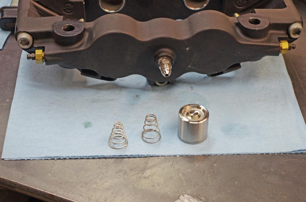
This first picture shows the old and new knockback springs for the rear calipers. The new stronger rate spring is on the left (larger diameter wire).
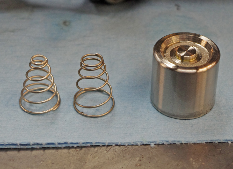
This is a close-up of the two springs. The small end of the original Wilwood spring wrapped around the nub on the rear of the caliper piston, so that it stayed attached even when the piston was removed. The new spring ID on the small end is too small to fit over the nub, so I just reversed the spring in the bore, with the large end facing the piston. This is how Wilwood had installed the springs on the larger pistons of my front calipers. So I figured it must be ok to do.
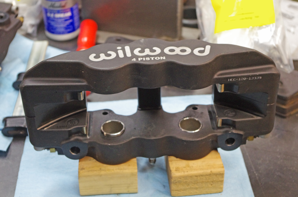
This picture shows the rear caliper pistons.
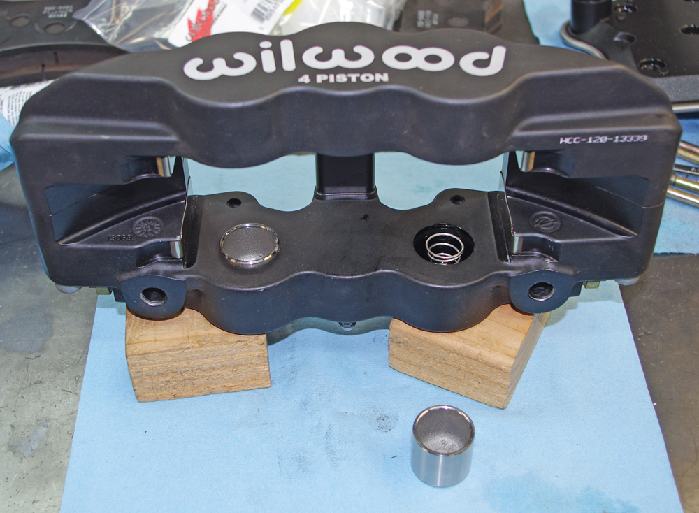
This is a rear caliper piston just prior to being reinstalled with the new spring, which is sitting in the caliper bore already.
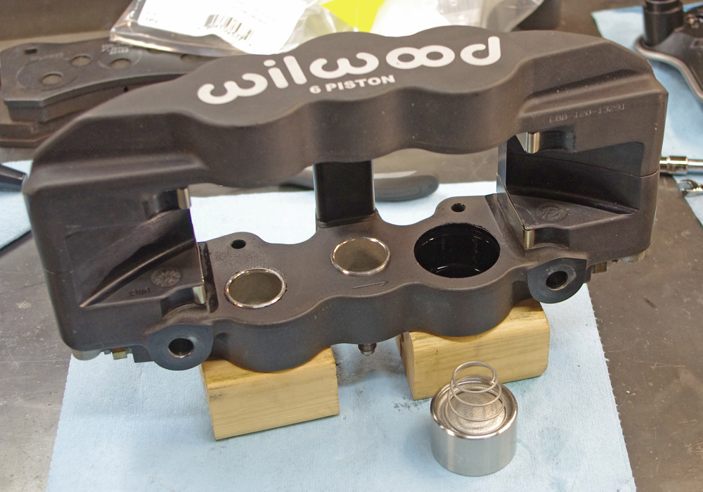
This is a front caliper with the larger size piston removed. The picture shows the Wilwood factory knockback spring sitting on the piston in the "as-installed" orientation.
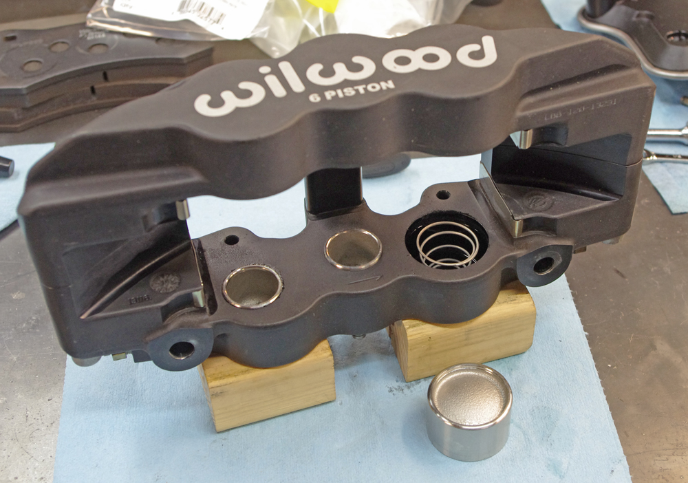
Here is the large diameter spring sitting in the bore prior to installation of the large diameter piston.
More to come on this...
-
01-26-2017 #102 Registered User
- Join Date
- Mar 2010
- Posts
- 469
I had no idea this could be done. Awesome post. Thank you.
01-27-2017 #103
 Registered User
- Join Date
- Feb 2013
- Posts
- 1,557
+1, good work.
01-27-2017 #104
Starting The Transformation
- Join Date
- Feb 2010
- Location
- El Segundo, CA
- Posts
- 268
I drove the truck around today. Was not able to induce knockback like I could before. That means it is improved, though does not prove I eliminated it completely. It's hard to duplicate autocross or track cornering loads on the street.
I only upped the rate of the knockback springs in the rear calipers. I left the front alone. The original springs had a rate of just under 4 lbs/in and the new springs are just over 8 lbs/in. So the rate is a little more than doubled. This made a big difference. The springs are now easily able to push the calipers pistons back out after you push them in all the way. They don't push them completely out of the bores though. But it was tricky to reinstall the calipers, as the pads had to be pushed out while at the same time guiding the caliper over the mounting studs.
There is noticeable brake drag when trying to turn the rotor by hand. Also, with the truck on the ground and in neutral, it is harder to push it back and forth (as I do when opening and closing the garage doors). While driving I cannot really notice the drag. I put the truck in neutral and coasted up to some stops signs and it was only at the very last moment before coming to a full stop that I could notice any extra drag. Most people would never detect it if they drove the truck I suspect. I consider this solution less than optimum, but I will probably stick with it for now.
Longer term I plan to punt on the manual brakes idea and add a small diameter vacuum booster. That will allow me to increase brake master cylinder sizes (front and rear). My personal experience with manual brakes has been that by the time I have the pedal effort down to something tolerable, the brake pedal is too spongy due to the smallish master cylinder bores. Sort of defeats the purpose. When I build my new frame I'll build a brake pedal arm that allows me to mount the booster, balance bar assembly and master cylinders under the cab.
I've read a great deal on the subject of brake pad knockback. The issue is quite common and there is a ton of info about it on the web forums. Different groups of folks, depending on the type of vehicle they are into, attribute knockback to various causes. Wheel bearings are one common culprit. Also, for folks with live axles, the GM design with the C-clips is frequently blamed for causing flex and thus knockback. I gather the C-clip can allow axial play in the rear axles, which some folks try to shim out.
I installed a dial indicator to one of my rear rotors to try to measure the rotor runout:
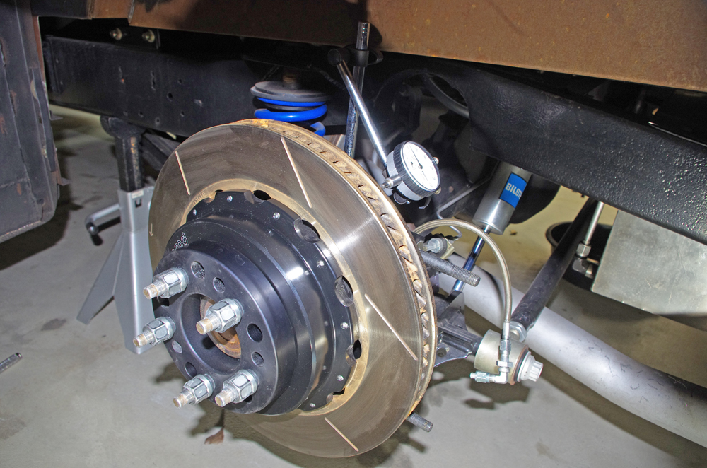
The runout was not bad, around three thousandths of an inch. But what was surprising was that by simply grabbing the rotor with two hands and trying to flex it back and forth I could more the dial indicator by almost 0.015" ! That makes rotor runout irrelevant. My axles and axle housing are made by Speedway Engineering so I called them to ask if this was to be expected. They said yes, it is unavoidable with the standard (non-floating) setup. And it is much worse during actual driving and hard cornering. It is due to the the rather long and narrow axles flexing along their length in response to torque applied by the wheel. Wow, that really made it clear to me why you want to run a floater axle if cornering is on the agenda. I'll be switching to a Speedway Engineering Grand National floater with the new frame build.Last edited by Dr G; 01-27-2017 at 05:31 PM. Reason: used wrong word
02-19-2017 #105
Starting The Transformation
- Join Date
- Feb 2010
- Location
- El Segundo, CA
- Posts
- 268
As part of the planning for my forthcoming frame build I've been playing around with Suspension Analyzer to come up with my front suspension geometry. I could just use someone's existing geometry (parts) but for me that's no fun. And although I am fairly familiar with the theory of suspension, I am learning a lot by playing around with the analyzer. I thought I might share some of the results. Maybe someone is interested.
Here is a screen shot of the Suspension Analyzer software showing the geometry I've come up with so far:
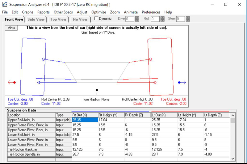
I started out my measuring my existing suspension and entering those values into the program. Then I changed things from there. I kept the same steering axis inclination (SAI) as I have now with my Wilwood Pro Spindles. They have a rather large 11 deg of SAI. Even though I plan to build new front uprights using Corvette ZR1 wheel bearings, I am thinking to keep the rather high SAI. Then, following the words of Ron Sutton, I set the caster at 11 deg also, to match the SAI. That's what I have on the truck now and it seems to work well. For no particular reason I have the static camber set at -2.0 deg. On my truck now I run -1.5 deg. On previous European cars I've driven around with -3.0° or even -3.5° camber. But that was when I was doing a lot of auto-crossing and track events, and on cars with front struts which have very poor camber gain.
My first goal was to adjust the control arm geometry in order to yield an acceptable camber curve. From researching the subject online it seems that a good target is around 0.8° of negative camber gain for the first 1 inch of suspension dive. Here is a curve showing my result:
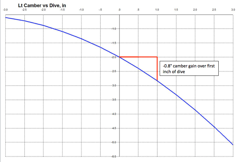
The shape of this curve is very easy to change by simply moving the pivot points for the upper control arm up or down.
My lower control arms are set level to the ground. This leads to the minimum amount of lateral scrub for the contact patches. So that the tires are not moving side to side as the suspension moves up and down.
With the lower and upper control arm angles set, the roll center is defined. As of now my roll center is 2.36 inches above ground. There is tons of discussion online and in magazines about the ideal front roll center location. There is even disagreement as to how to determine the roll center, force based or geometry based. Folks used to state that the roll center should not move around a lot in roll, though today folks are saying this does not matter so much. One could grow a beard trying to sort this out.
Generally the roll center height is expressed as a percentage of the CG height. I do not know my CG height, though I have corner scales so I will eventually measure it. The Suspension Analyzer program recommends 20 inches as a good guess, though for a truck I suppose it will be higher than that. If it were 20 inches then my RC is at about 10% of the CG height, which is in the range of values that folks recommend. If I want to I can adjust the roll axis inclination by raising/lowering the rear RC height via the Panhard bar.
And there is the issue that adjusting the RC height via control arm geometry will then change the camber curve. The two are related. My general sense is that the camber curve takes precedence over the CG height.
I played around a bit with using longer lower control arms (moving the inner pivots points towards the center of the truck). I found this had a pronounced effect on the lateral migration of the roll center during roll. I have no idea if it is desirable, but I landed on a length for the lower control arms that yields almost no motion of the roll center during roll. This has the lower control arms longer than what I have on the truck now, but it looks like a reasonable value for a custom frame and suspension build. A possible benefit is that longer lower control arms further reduce lateral scrub of the contact patches during suspension movement.
This curve shows the left right movement of the roll center as the chassis goes through roll from -3° to +3°
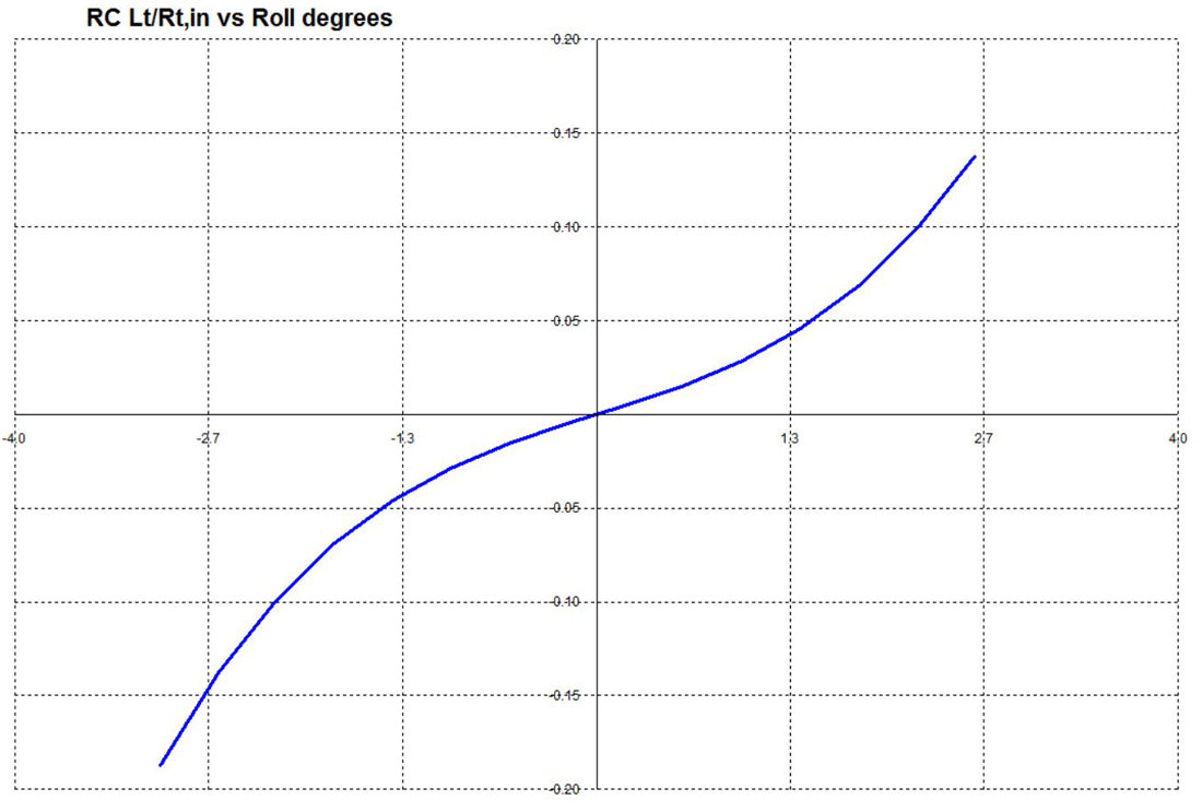
The graph shows less than 0.20 inches of RC movement, which is basically nothing, over a large range of roll angles. Again, I have no idea if this is beneficial or not.
My next goal was to dial in bump steer. I decided to limit myself to the length of a standard Mustang steering rack which is 24.25" from inner tie rod end -to- inner tie rod end. Commonly it is stated that one of the requirements for good bump steer is that the inner tie rod end must fall on a line drawn between the inner pivot points for the upper and lower control arms. Hard to explain without a diagram.
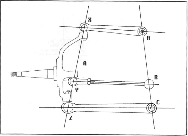
So basically B must be on a line drawn from A to C. However, since I lengthened my lower control arms, but still want to use a standard Mustang rack, this becomes difficult to do. The rack is too long unless I move it upwards considerably. However, there is an alternative configuration for the tie rods that will still yield good bump steer, and is shown in the lower diagram here:
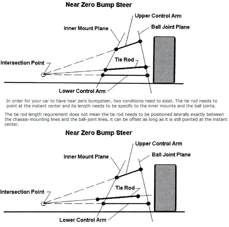
Honestly I think in real life this is how most vehicles end up being configured. Without B falling exactly on the line from A to C. From my own experience with measuring bump steer, the angle of the tie rods is more important than their length.
I played around with tie rod length and the height of the outer tie rod ends until I got reasonable bump steer. From my research this would mean 0.005" to 0.015" of total toe out during a representative amount of dive.
Here is what I have so far:
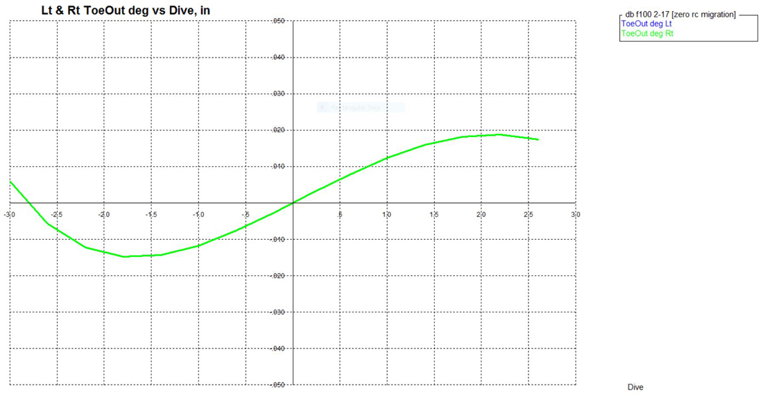
This shows a maximum of 0.19° of toe out (for one wheel) over 3 inches of dive. 0.19° of toe out equals 0.004" of toe out for a 27" diameter tire. So not too bad. From playing around with Suspension Analyzer I found that bump steer was extremely sensitive to the height of the outer tie rod end. Ultimately I believe good bump steer can't just be designed into the suspension. It has to be measured and adjusted on the final product.
More to come...
02-19-2017 #106
Registered User
- Join Date
- Apr 2011
- Posts
- 165
Nice. A bit over my head though. Are you going to use Wilwood Mustang Pro or C10 Pro spindles? I would imagine with a truck - C10? http://www.wilwood.com/Spindles/SpindleList.aspx
02-19-2017 #107
Starting The Transformation
- Join Date
- Feb 2010
- Location
- El Segundo, CA
- Posts
- 268
No, as mentioned above I plan to design and have built my own spindles, using ZR1 hubs. Just because I like doing it, not because what's available is no good.
02-19-2017 #108
Registered User
- Join Date
- Apr 2011
- Posts
- 165
Guess I missed it. I need to pay better attention. Originally Posted by Dr G

02-20-2017 #109
Starting The Transformation
- Join Date
- Feb 2010
- Location
- El Segundo, CA
- Posts
- 268
No worries. I was glad you posted your link to the new Wilwood C-10 spindles. I was not aware those existed. I just did a crude PowerPoint check which shows the "built-in" SAI of those spindles to be 7°. Compared to 11° for their Mustang II derived Pro Spindle. Originally Posted by hotrod56
I put "built-in" in quotes since that would be the SAI for zero degrees camber. When installed, every extra degree of negative camber increases the SAI by another degree. So in my case running the Pro Spindle with -1.5° camber, my actual SAI is 12.5°
The Wilwood C-10 spindle does look a bit more muscular than the Pro Spindle. That might be good for reducing flex (and knockback).
I've done some thinking about where flex occurs in the spindle/rotor combination under braking. Obviously as the pads squeeze down on the rotor, the moving rotor tries to pull the caliper forward along its circumference. But because the caliper is bolted to the spindle on only one side, there are other forces induced also. These amount to a "twisting" force on the caliper. I suspect that the standard way of bolting the caliper to the spindle using an adapter bracket is not ideally suited to withstanding this twisting force.
In designing my own spindle I would like to do away with the adapter bracket altogether and have the caliper bolt directly to the spindle. As it would be on a dedicated racecar. You can see the idea in this picture of a spindle, manufactured from steel in this case. I think this is from a WRC or Touring car, not sure.

I plan to have my spindles CNC'd from 7075-T6, for now anyway, my approach may change.
02-20-2017 #110
Starting The Transformation
- Join Date
- Feb 2010
- Location
- El Segundo, CA
- Posts
- 268
Here is another screen capture from the Suspension Analyzer software. It shows how my current design behaves under 3° roll and 0.7" of rack movement (steering input). See the numbers I've outlined in Green:
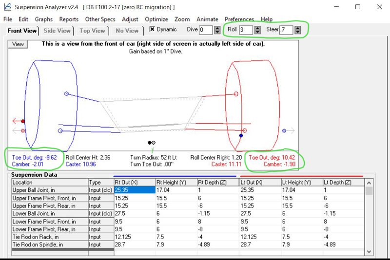
This is where the effects of caster come into play. In one way it is possible to think of caster as inducing "dynamic camber". With 11° of caster, and with the wheels turned to the left some 10°, the outside front tire is still at -2° camber, even though the chassis has rolled 3° to the outside. The plus side of this effect is that you can run less static negative camber. This would help with braking and tire wear. But too much caster has negative effects also. Heavy steering due to increased trail is one such effect. Ron Sutton mentions some of the other side effects in his excellent suspension summaries.
02-26-2017 #111
Registered User
- Join Date
- Jun 2013
- Posts
- 16
Big fan of your build thread!
Lots of tech details and fabrication, also your subject is one of my favorite trucks, been admiring those bulbous lines since I was a kid.
Our builds are very similar, I am currently swapping in a A-arm front end so the suspension design parameters are very useful, though I am not brave enough to design one from scratch.
Stephen
04-02-2017 #112
Starting The Transformation
- Join Date
- Feb 2010
- Location
- El Segundo, CA
- Posts
- 268
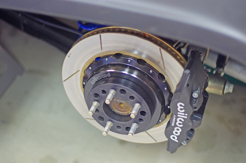
As part of my ongoing experimentation I have been playing around with wheel spacers. I had two goals in mind. The first was to see how close I can push the tires to the fenders and still have adequate clearance when going over bumps and when turning. The second goal was to see how the steering felt as I varied the scrub radius.
Here is a pic of a spacer on the rear:
Here is a picture of a few spacers showing the different thicknesses:
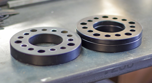
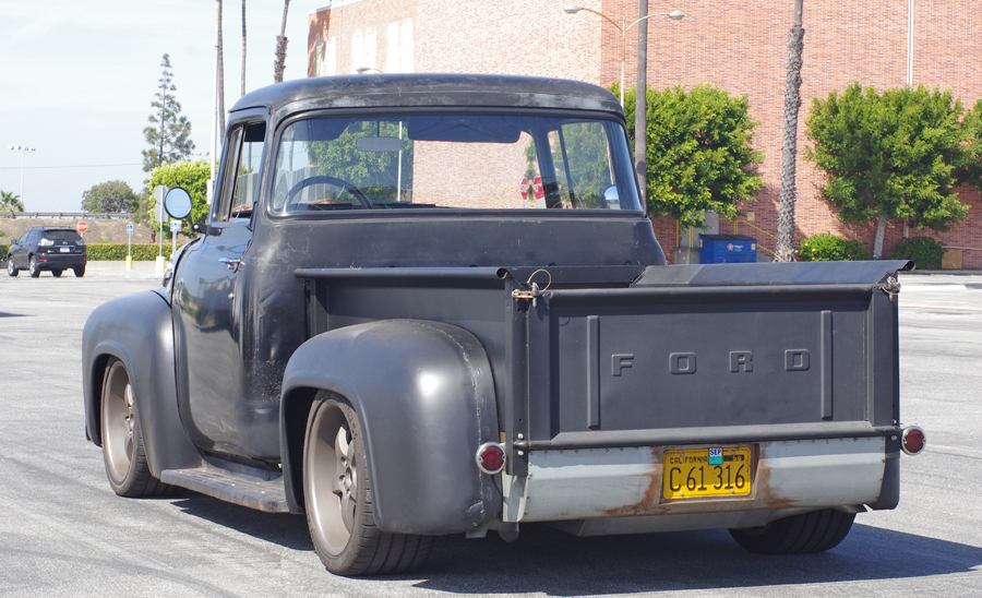
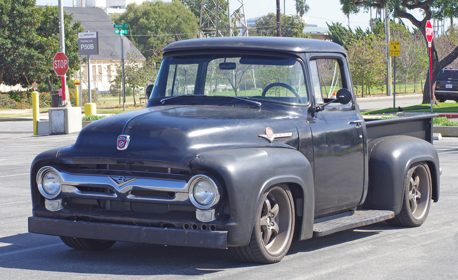
In the final analysis I ended up going 1/2" outwards with each front and rear wheel. That increased my track width by 1" front and rear. I drove around a bit over some bumpy stretches, and did some parking lot maneuvers and all is well, no rubbing.
I need to know this when I order my new wider wheels. How wide can I go and what offset will I need? Keeping in mind that these wheels will be added along with a new frame and suspension. So I can build in any hub-to-hub width I want to match the wheels.
I want to keep with the theme of having the same wheels front and rear, so that I can rotate, and because I think it looks better that way. That's referring to the offset part. Having the same width wheels and tires front and back is an absolute requirement for me. But unless the offsets are the same, you cannot rotate obviously. And I do not like the look of super deep-dish rear wheels when the fronts have much less.
One interesting thing I learned during this exercise is that the steering feel is quite responsive to small changes in scrub radius. I changed the front spacers from 1/2" which I had been running, to 3/4" and then to 1". Each time I noticed that the steering effort increased as did the self-centering tendency. I would say that the steering feels better with the 1" spacer than it did with the 1/2" spacer (1/2" extra scrub radius). Interesting lesson. As with so many things, some scrub radius is good, too much is bad. I'm not sure that zero scrub radius is really a valid goal. I think it would really sap the steering feel. This theory is in line with some stuff I've read over time also.
I am currently running 19" x 10" wheels with 285/35-19 tires. Just from a space perspective I could easily go to 12" wide wheels in the back with the mini-tubs I have now. There is an easy 2 inches of clearance between the inside edge of the rear tires and the mini-tubs. Up front the situation is not so clear. I expect no problems with a 19" x 11" wheel and 305/30-19 or 305/35-19 tire. The next step up would be maybe an 11.5" wide wheel with a 325/30-19 tire. I have to carefully check the clearance from the rim to the various suspension pieces at full lock.
Fyi, I do not plan to do any aggressive driving with these large spacers installed. I have long wheel studs, so that was not a problem in terms of mounting them up. But it is really just an experiment.
Here's a few pics of the truck with wider track:
04-02-2017 #113
Registered User
- Join Date
- Sep 2011
- Location
- Southern Ontario
- Posts
- 640

The wheels look great pushed out that far!
04-03-2017 #114 Registered User
- Join Date
- Feb 2005
- Location
- Minneapolis, MN
- Posts
- 195
It always amazes me on how much trucks just make wheels and tires look small. Especially width. Looks great though!
04-03-2017 #115
Registered User
- Join Date
- Feb 2013
- Posts
- 1,557
Love the wider track width!
04-03-2017 #116
Starting The Transformation
- Join Date
- Feb 2010
- Location
- El Segundo, CA
- Posts
- 268
I know, no kidding. That's why I am avoiding 18" wheels. They would just dissapear. Originally Posted by brawls43
04-07-2017 #117 Registered User
- Join Date
- Aug 2007
- Location
- Jonesboro, Arkansas
- Posts
- 2,506
I must say... I'm impressed with your skills
Carl Wilson
1968 Camaro - T-56 6 speed - 383 Stroker, 2014 Mustang GT seats. FiTech EFI, Tanks Inc. Tank with Deutschwerks fuel pump.
04-08-2017 #118
Starting The Transformation
- Join Date
- Feb 2010
- Location
- El Segundo, CA
- Posts
- 268
Thanks. I just try to combine my engineering training with some common sense. The fabrication skills I'm learning all the time. I do all the homework I can on a subject and then, as my old college friend used to say, "there is nothing left to do, but to do it". Originally Posted by minendrews68
05-01-2017 #119
Starting The Transformation
- Join Date
- Feb 2010
- Location
- El Segundo, CA
- Posts
- 268
Some who are following this thread know that I plan to build a new frame soon. With new suspension of my own design and fabrication. A big part of the front suspension is the spindle, as the dimensions thereof dictate a lot of other parameters.
For a time I was thinking I would keep an SAI value around what I have now with Wilwood Pro Spindles, namely 11 deg. Which is a lot. But I have been going a lot of studying, as well as driving around a lot in my truck and I've done a bit of an about face on SAI. I now think I want to go for something like 5 deg. With around 0.5" of scrub radius and 7 deg caster. Achieving low scrub radius with low SAI is a challenge, as the wheel mount surface (WMS) to SAI distance has to be on the small side, or you have to use big offset wheels, or both. I have developed a little spreadsheet calculator that allows me to quickly plug in values for SAI angle and WMS to SAI distance, along with wheel offset, to arrive at scrub radius. I've resisted going to big offset wheels as I am not sure the look is in keeping with my 50's truck, but I am slowly giving in to reality.
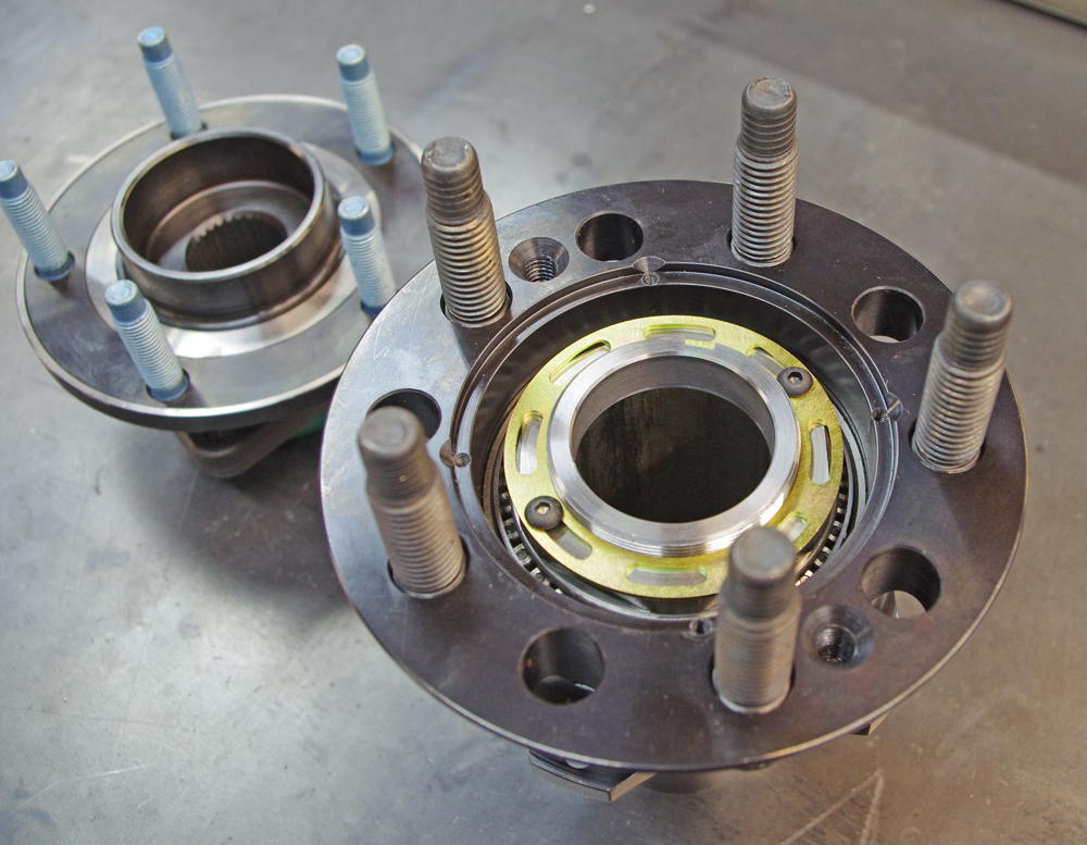
Since I plan to build my own spindles one of the first things to decide on is what snout/bearing/hub combination to use. For a long time I was planning to go with Corvette ZR1 hubs (SKF) which seem to hold up pretty well, though some users still complain about caliper piston knockback. Though it is never possible to completely determine if they have it in the front or at the rear. I've had a ZR1 hubs sitting here on my desk for a few months, just sort of staring at it. It's an interesting design actually, sort of an inside-out spindle. The wheel mount surface and the spindle are one part, and the spindle extends inward instead of outward. The portion that bolts to the upright only holds the bearings. The package is manufactured by mechanically rolling the end of the spindle over the inner bearing. This must be a tough exercise in terms of getting the preload on the bearings just right. And that might be why only the SKF (ZR1) bearings are thought to be all that good, even though other brands have similar overall dimensions.
After some time I started wondering if the ZR1 bearings are really as stiff as I would want to avoid flex induced knockback. Chris Alston's ChassisWorks sells a bearing that is similar to the ZR1 unit, just bigger in all dimensions. I do not know if they make it or if it is from some other application and they just sell it. A pair will set you back $1400, so they are not cheap. I considered this path for a bit, but kept looking around for alternatives.
http://www.cachassisworks.com/p-3202...hubs-only.aspx
I started reading some desert racing forums, and learned that they often use circle track hubs and snouts (the snout being the part that sticks out, that the bearings and hub slide onto). Since I have been looking into doing a Speedway Engineering rear floater, which also uses circle track hubs and bearings, the two paths sort of lead to the same place. This:
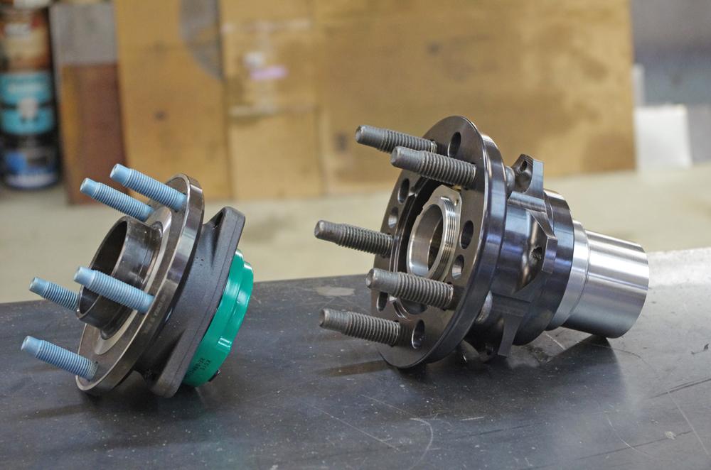
On the left is a ZR1 hub. And on the right is a Grand National 2.5" OD 5x5 snout and hub. I'd been looking at pictures in catalogs and on the web of these parts for quite a while. But I was still awestruck by the immense size of these parts relative to what I am used to. You might think they would be heavy too, and you'd not be wrong. The ZR1 hub on the left weighs 8.5 lbs according to my scale, and the parts on the right weigh 12.5 lbs. Though the steel AllStar hub I bought for measuring weighs 8.5 lbs by itself. There are better designed steel hubs or aluminum hubs that are down around 5 lbs, so then the difference starts to be not all that much. I would also plan to machine off the "ears" on the back of the hub where the rotor adapter is meant to bolt to, as I would use a standard aluminum brake hat the mounts over the studs. I think it can be close to a wash on weight with carefully chosen parts.
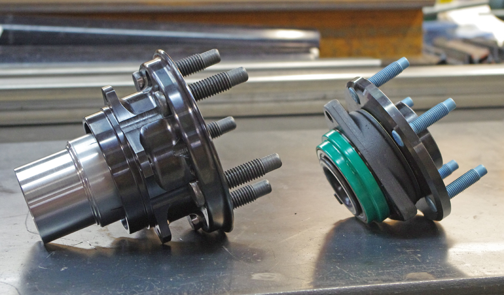
Another thing one can see is that it will be tricky to integrate this hub and snout into a spindle while keeping the WMS to SAI distance small. I am shooting for 3 inches on that dimension and it's already 3 inches just from the WMS to the end of the hub.
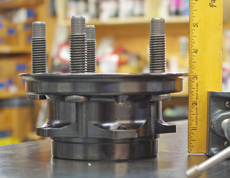
So my SAI will have to pass right through the back edge of the hub. Is this possible? I think it is, I just have to think outside the bun a bit when designing the spindle, which I am still working on. I thought about machining a bit off of the back edge of the hub, but that is where the seal installs, so there is not much scope for that. If I made my own hubs I could probably pull the WMS inwards about 0.5" - 0.75", since there is about that much "wasted" space past the outer wheel bearing. But that seems like a lot of work for a small reward. You can sort of see what I mean in this picture:
This pic also shows the way the hub nut is held in place. No buggy-era cotter pin!
I'll continue this hub discussion some more in a following post.
05-05-2017 #120 Registered User
- Join Date
- Aug 2010
- Location
- now In Dandridge, Tn.
- Posts
- 1,301
Congrats on the progress and approach. I would like to toss in $.02 if I may. I use the Coleman short snout spindles on our Sniper front subframes for the F-body cars. My experience with the large bearing hubs gives me a ton of confidence in these parts. Coleman will make you spindles in about any combination you design for them (not too expensive) with bolt on steering arms and a bolt on upper ball joint receiver. This can help in final tuning.
Big SAI numbers matched with big caster will work, but can produce a 'jacking' effect on the inside tire. - this can be somewhat useful on 'big bar/soft spring' set ups, but a penalty for guys that like heavy springs. Very low SAI/caster, like the 'Vette stuff works great (on a Vette) if you have a very low Center of Gravity (CG). I am now mostly working in the 6/7* range. Next, and this is from the drivers seat, low scrub radius looks great on paper, but with a scrub of less than 1 1/2", you can't 'feel' the tire. So, I like around 2" of scrub. If this was a pure track car, on slicks, with Mario behind the wheel, maybe less. One more thing, do some searching and look at how the long travel sand car guys make their spindles from tubing with mono-balls. Pretty clever. Keep it up Dr.G. Looking awesome!

 Reply With Quote