

Results 81 to 100 of 132
-
05-04-2016 #81
 Registered User
- Join Date
- Dec 2015
- Location
- Ruhr-Area, NRW, Germany
- Posts
- 313

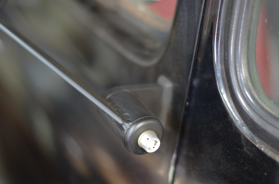
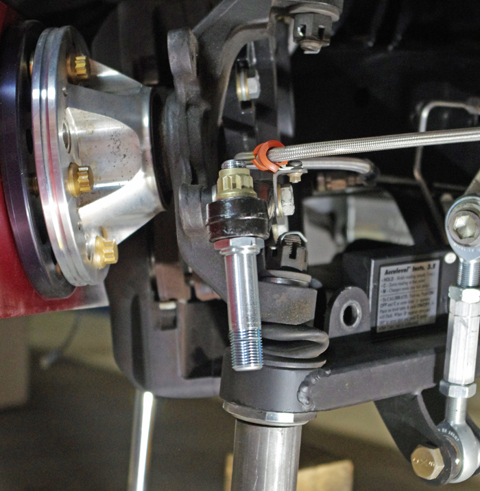
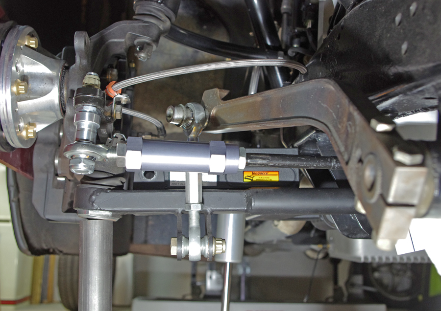
I am sorry to jump into your nicely built sandcastle but that tie rod attachment is unsafe and i hope you're not hitting the road like that.
I guess you already noticed that the locknut does not even thread down far enough for the plastic to touch the bolt threads.
Other than that, good job! I really like your truck and your ingenuity!
1985 Dodge Power Ram W250 3/4t 360/518/241
2005 Dodge Ram 1500 SRT-10 505/T56/D60 small upgrades
-
05-04-2016 #82 Registered User
- Join Date
- Jul 2011
- Location
- Prescott, AZ
- Posts
- 206

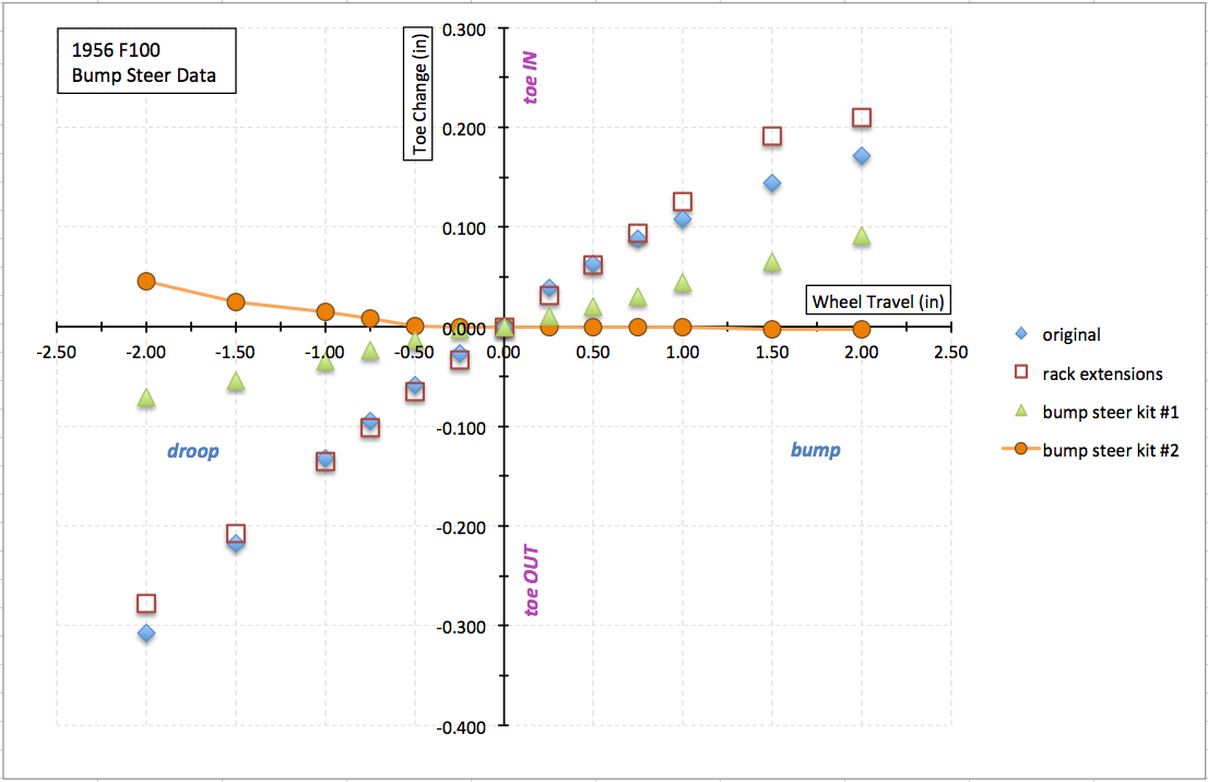
Those are impressive results! Its interesting to see how much difference a small spacer can make.
05-04-2016 #83 Starting The Transformation
- Join Date
- Feb 2010
- Location
- El Segundo, CA
- Posts
- 268
Actually that locknut is fully engaged. Just barely, but enough. In any case after those photos were taken I replaced those nylock nuts with mil spec flex top nuts similar to what is shown here: Originally Posted by kingcrunch

http://www.mcmaster.com/#hex-locknuts/=129ql61
These offer resistance almost as soon as they are engaged, so no worries.
Now, I'll be the first to admit that hanging a tie rod of the end of a cantilevered stud mounted in single shear goes against all proper engineering common sense. But this technique is nonetheless very common, even in racing. Here's a few photos of BMW E30 and E36 Gr A and DTM race cars that I have from my earlier days. That is where I first learned of using this technique to correct bump steer and roll center on factory type cars that were heavily lowered and no longer had good geometry. These are factory prepared race cars:
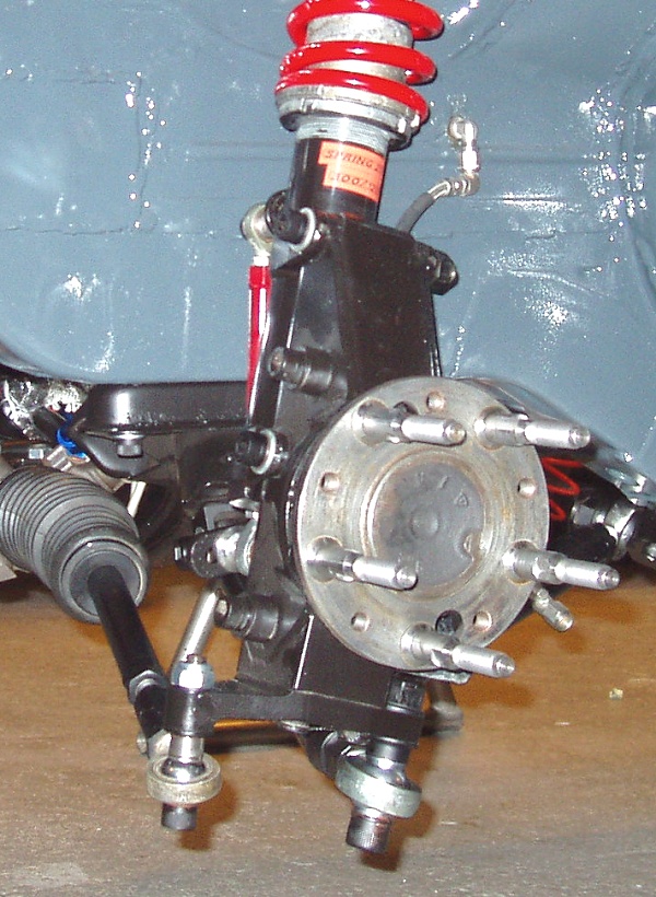
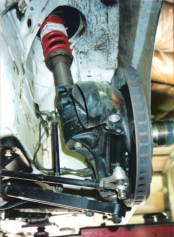
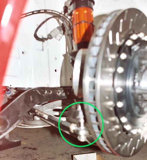
This is all preparation for my plan to build a custom frame. At that point I can relocate the rack, which means moving it upwards where it might interfere with the oil pan. Or I could make new steering arms that position the outer tie rod end further down without the need for the cantilevered stud.
Gustave
05-04-2016 #84
Starting The Transformation
- Join Date
- Feb 2010
- Location
- El Segundo, CA
- Posts
- 268
Yes, no kidding. Although the bump steer kit made the most difference, I suspect the final results would not have been so good if I had not worked first on getting the tie rod the right length with the rack spacers. Originally Posted by Centerforce
Gustave
05-07-2016 #85
Registered User
- Join Date
- Feb 2011
- Location
- central WI
- Posts
- 53
Do you still happen to have the link for the circled mirror part of your homemade mirror set-up? Originally Posted by Dr G
05-07-2016 #86
Starting The Transformation
- Join Date
- Feb 2010
- Location
- El Segundo, CA
- Posts
- 268
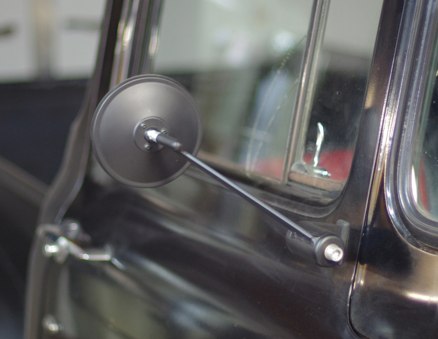
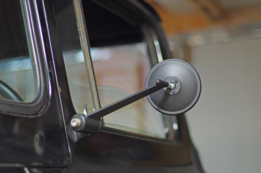
Yes, here it is: Originally Posted by rab
http://www.amazon.com/Grote-28032-Co...ilpage_o00_s00
05-11-2016 #87 Registered User
- Join Date
- Aug 2010
- Location
- now In Dandridge, Tn.
- Posts
- 1,301
congrats on the bump curve. At first it looked to me that the rack was too low, the way the curve set, but you seam to have solved the issue. We spend a lot of development time getting this right on the money. With most performance based IFS systems, we try to gain a little toe out during bump, and a '0' net on droop. This trick can be used to create a small amount of toe 'out' in a hard corner and help to reduce understeer. - let that swirl around in your head for a while. Anyway, great work, and I'm sure it will pay off. Have you driven it with the corrections? Originally Posted by Dr G
05-12-2016 #88
Starting The Transformation
- Join Date
- Feb 2010
- Location
- El Segundo, CA
- Posts
- 268
Hi Rob. Yes, I read about the "toe out in bump" theory when I was researching what to use as a bump steer target. I can see how it could be achieved with enough fiddling of rack and tie rod end locations, though I do not yet intuitively understand how it would reduce understeer. Originally Posted by RobNoLimit
I did drive around with the new corrections. It rides real nice. Very smooth.
Gustave
05-17-2016 #89 Registered User
- Join Date
- Oct 2015
- Posts
- 122

I really like what you've done to this build. Stance is great also. I too have been considering the JRI Ride- Height coilovers. A bit pricey but I also have a low scrub height (3.5") and the JRI Ride-Heights seem to be the best solution to clear the speed bumps etc. Keep up the great work on your awesome truck.
07-23-2016 #90
Registered User
- Join Date
- Jun 2015
- Posts
- 175

not being a hater and all for dyi,but novice welding on highly stressed parts?regards
09-02-2016 #91
Registered User
- Join Date
- Aug 2016
- Posts
- 33
I really like your attention to detail! Tend to hyper focus on minute details, and projects take me forever because of it. I love the project. Forgive me if you've said it before, but you must be some sort of engineer ��
09-02-2016 #92
Starting The Transformation
- Join Date
- Feb 2010
- Location
- El Segundo, CA
- Posts
- 268
PhD in Mechanical Engineering from UCLA. Worked for McDonnell Douglas for a while designing airplanes, then TRW designing spy satellites, then DIRECTV also on satellites and rockets launches, and eventually on antennas. If you look on any roof that has a DIRECTV dish, the little pointing mechanism that allows it to point it's narrow Ka beam to a satellite 25,000 miles away, that was designed by me (11 patents). Been building stuff since I was 14, when I built a full suspension BMW bike with XR75 front forks. That bike could really jump. I still recall drawing out the frame life-size on butcher paper on my mom's living room floor, cutting and mitering the tubing by hand and having a friend's brother weld it up. Originally Posted by LT1C1500
11-25-2016 #93
Starting The Transformation
- Join Date
- Feb 2010
- Location
- El Segundo, CA
- Posts
- 268
This write-up is just about some planning, not about actual progress.
Ever since I got my truck back from a prior builder I've been disappointed with where he positioned the engine. He didn't go nearly as low as I think he could have gone. Mainly because he was limited by the (standard for him) subframe that he welded in. He installed the subframe first, then tried to get the engine as low as he could and of course, with a Ford, ran into interference between the oil pan and the subframe/steering rack. Even though the engine has a rear sump oil pan, there is still a small front "mini-sump", which even has it's own drain plug. This is to accommodate the front mounted oil pump.
I think he should have installed the engine first, and then built a custom subframe "around" the oil pan. But that would have been too much work. It is, however, what I plan to do when I build my own frame.
During a recent build-phase I constructed new control arms, added new front shocks and installed an AODE transmission, as can be seen higher up in this thread. The reworked suspension required relocating the steering rack, and this in turn required re-routing the steering shaft. Due to a clearance issue I had to lower the front of the engine about 1 inch. I did this by making new motor mounts. The only reason I could do this and the prior builder could not was because the steering rack had been moved out of the way.
The prior builder installed my current 347 engine with a carburetor. As such he canted the engine up at an angle of 3 deg or so, probably a little more. I've since converted to EFI. From studying the subject I am convinced that an engine with EFI can run at 0 deg inclination (flat). There is no longer any need to tilt the engine backwards as had been the habit for so many decades. This allows quite a bit of scope to lower the front of the engine. As mentioned above, I lowered the front of the engine 1 inch, but would have to lower it quite a bit more to get it flat. You do have to keep your driveline angles in mind when during all this.
An interesting thing happens when you lower the front of the engine. The valve covers move away from the firewall. This then produces scope to push the engine backwards. A win-win.
If one is determined enough in lowering the engine in their Pro Touring truck, eventually it will get down there far enough where it will start "competing" with other parts of the vehicle for who can scrape the ground first when and if things start to bottom out. This is when people start talking about things like dry sump oil pans in order to get a little extra clearance. That's just fine if you're running a compact manual transmission. But if, like me, you have an automatic transmission, then things are a little different.
One look at this picture will sort of illustrate the issue:
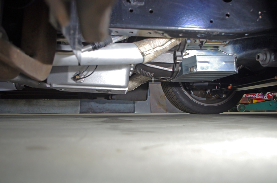
Here you can see how far the AODE transmission pan hangs below just about everything else. I should make clear that this is an extra capacity B&M pan. Basically the biggest pan I could find. I bought it before I really understood how far it would protrude downwards. I was just thinking of extra capacity and extra cooling at the time. The picture also makes it obvious that a dry sump system for the engine would be of little benefit for me. The transmission bell housing is already as low as the existing oil pan.
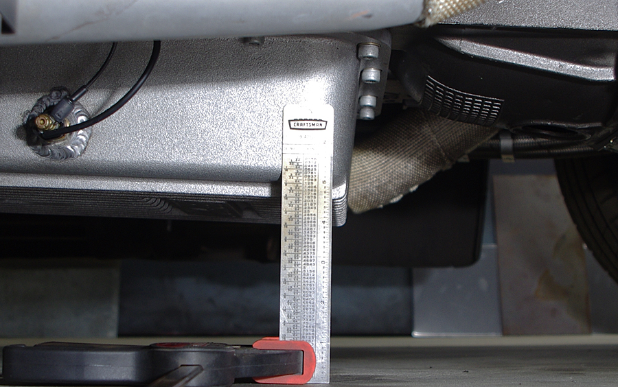
Here I have a little ruler to show the actual ground clearance of the transmission pan, which looks to be about 4.5 inches. It was lower before as I just finished raising the front of the truck a bit by welding new lower shock mounts on to my lower control arms. When I built the control arms and installed the new (shorter) shocks I did a lot of measuring and calculating, but nonetheless my ride height ended up a little low. And I could not turn the spring perches down far enough to compensate. So I moved the lower shock mounts up 1 inch, moved the upper spring perches up 3/4 inches and voila, a tad more ride height.
11-25-2016 #94
Registered User
- Join Date
- Apr 2011
- Posts
- 165
Hey Dr G Originally Posted by Dr G
Why dont u get rid of the pan, and make a new one, that is wide and shallow like your oil pan?
11-26-2016 #95
Starting The Transformation
- Join Date
- Feb 2010
- Location
- El Segundo, CA
- Posts
- 268
Well you read my mind. That is what I have in planned. Originally Posted by hotrod56
At a minimum I have to get rid of the deep sump B&M pan. It's just and accident waiting to happen. Though surprisingly I've scraped and bottomed the truck at various times, and yet the trans pan is pristine.
What I plan to do is fabricate a pan out of steel plate (0.250" rail and 0.125" pan). It won't be the lightest thing in town, but compared to the weight of the transmission it will be inconsequential. And it will offer at least some resistance to scraping the ground if/when that ever does happen. And it won't crack/shatter like a cast aluminum pan would on impact. After I weld it up and leak check it I will have a local machine shop fly-cut the gasket mating surface to true it up.
I'd like to make my custom pan as shallow as possible. How shallow is this? That is something I am still investigating. The following picture gives me some clues:
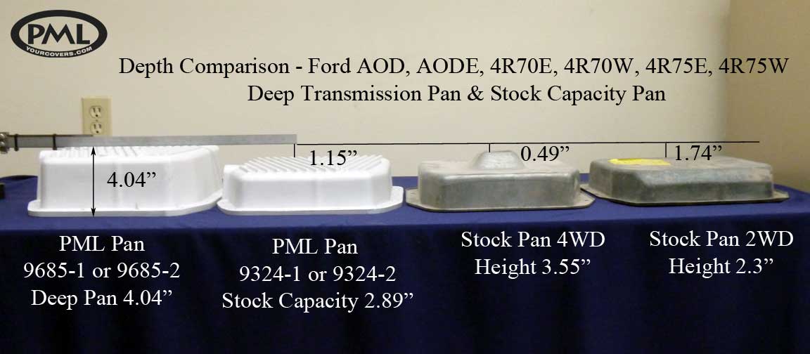
I would like to build a pan with a 2.3" depth like the one shown on the far right. I know my B&M pan is at least 4" deep probably more. So that gains me 2 inches of ground clearance right there. Nothing to sneeze at.
I'm just not totally sure if the pan shown on the far right is a standard 2WD AODE pan or an AOD-only pan. I know the bolt pattern is mostly the same for the AOD, AODE and 4R70W transmissions, but the AOD used a very different filter. The AODE/4R70W has two different filters for 2WD and 4WD applications:

Just looking at the filters it would seem to make sense that the 2WD filter is meant to work with the flat 2.3" deep pan, and that the 4WD filter is meant to work with the deeper 3.55" pan with the protrusion in the middle of it. That's what I'm going with for now, unless I learn something different. Sometime soon I will pull my B&M pan and check clearances for myself.
I am not happy about the loss of fluid capacity. As hotrod56 mentions, I have thought about flaring out the pan to the sides, similar to what is commonly done on road racing engine oil pans to gain capacity. But with the shallow depth it will make it tricky to access the bolts that attach the pan to the trans. I could get tricky and weld small tubes around the bolt holes to seal them to the gasket and them use longer bolts, or use bolts with sealing washers like the drain plug, or even a two-part pan. I've seen all these techniques used for oil pans. But there is not unlimited room to flare out the pan in any case, as the exhaust runs pretty close by. It will take some thinking. If I could get an extra two quarts capacity from the effort it might be worth it.
I've also thought about adding the equivalent of a surge tank to the return line from the transmission cooler. Just an empty aluminum tank to hold a few quarts of fluid. Fills from the bottom and exits from the top, non-vented. It should not add very much load to the transmission fluid pump. It would be kind of like a dry sump tank I guess. I can't think of any reason this would not work.
More to come on this.
11-26-2016 #96
Registered User
- Join Date
- Apr 2011
- Posts
- 165
I have the same problem, but with GM 4L80e. Originally Posted by Dr G
11-27-2016 #97
Registered User
- Join Date
- Dec 2010
- Posts
- 708
I just went through the realities of dealing with the 4r70 pan with the '63 Ranchero I put together last summer (recently sold to Tennessee). It had a 2wd setup (from 1997 Exploder), but that pan with the dumb bump on the bottom came with it, as did the filter that protrudes into the thing. The non-bump pan is like a unicorn, so I just tolerated things, and, like you, bumped the front end up an inch (about the depth of the bump) to compensate.
If you're stuck with that transmission, I'd say the best you'll do, given the low height of the inner workings of the transmission inside of the basic pan volume, would be to find or fabricate something along the lines of that flat 4r70 pan; again, finding one seemed rather difficult (one could just take the bump pan and cut/weld flatness in). Your idea of adding fluid capacity via a remote sump/cooling system seemed the best way to go (versus fabbing bolt tubes into a widened pan that can only get so shallow).
The 6l80 in my Falcon had a much easier (anti-truck) pan solution in the form of the Pontiac G8 pan, which chopped a good couple inches off the bottom . . . Looking at it from the side view makes me re-think a manual, if only for the sake of ground clearance. No.
12-01-2016 #98
Starting The Transformation
- Join Date
- Feb 2010
- Location
- El Segundo, CA
- Posts
- 268
As another post of "things yet to come", I just received this thing the other day:
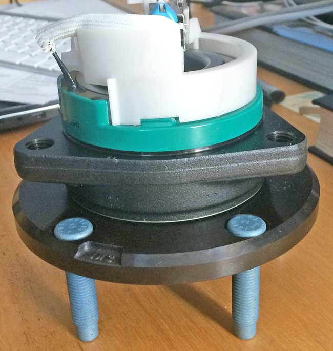
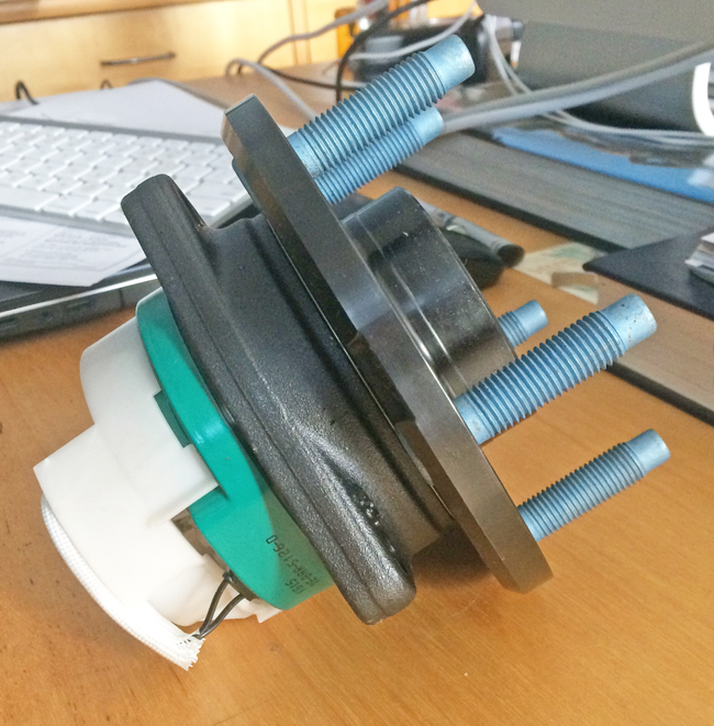
This is an SKF "race" hub for the C6 Corvette. Supposedly equivalent to the SKF factory hub for the C6 ZR1. I bought this from PFADT in Corona CA.
I got this to mainly to sort of check it out and take some measurements. As part of my plan to build a frame, I would like to build my own front uprights. Right now I am using the Wilwood Pro Spindles and they are ok, but I think they can be improved on. I like the idea of the spindle snout, wheel bearings, and hub being an integrated unit as is the case on this piece here. It also makes it a bolt-on affair so it's fairly easy to add it to a machined steel or aluminum upright.
There is much discussion on Corvette Z06 forums about these wheel bearings, what fits what and so on. I think a lot of that centers around the number of splines for the rear axles and the compatibility of the wheel speed sensors. Neither of these concern me of course. I am only interested in stiffness. From what I've read I believe this SKF unit to be the stiffest and most durable unit known to exist for the C6.
I also considered the wheel hub from the 2015 Z28. It looks very similar. My thinking is that the Z28 is a heavy car with huge front tires, so the wheel bearings must be something special. But a little investigating shows that it shares the same front wheel bearing as the Camaro ZL1 going back to 2012. So it was not specific to the 2015 Z28. The Z28 weighs almost 3900 lbs. A Corvette C7 GS weighs 3400 lbs but I think the C6 ZR1 weighs 3350 lbs, but arguably with a more "sporting" intent. Not sure how this would have affected Chevy's decision making when spec'ing out the wheel bearings. The factory wheel bearing for the 2015 Z28 is on back order right now. Eventually I might order one to inspect it.
01-08-2017 #99
Starting The Transformation
- Join Date
- Feb 2010
- Location
- El Segundo, CA
- Posts
- 268
This is a follow up to the discussion above regarding the amount of ground clearance I had relative to my deep sump B&M transmission pan.
I decided I was not comfortable with it, and that I had to improve the situation. My first solution was to see if I could find a 2WD AODE pan. I assume this would match the available 2WD filter, and should provide more ground clearance than the common 4WD pan.
I found a pan on an auction site that was advertised as AOD/AODE/4R70W, and it looked like a flat bottomed pan that I wanted. I went ahead and purchased it, cleaned it up, flattened it out. Then when I compared it to an AODE gasket I discovered it would not work. Not only did the holes in the pan not match the gasket. But the gasket rail of this pressed steel pan did not even match the 'shape' of the AODE gasket in one corner. See pic below, upper left-hand corner:
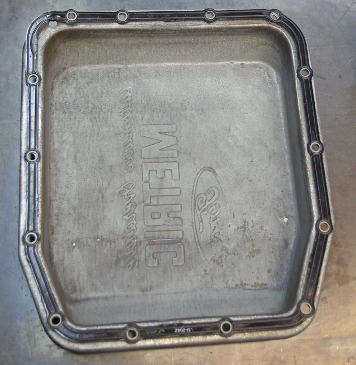
I can only assume that this pan I bought is specific to the AOD transmission only and will not fit an AODE nor a 4R70W. So I decided to make my own pan to my own specs.
Here is a picture of the AODE transmission pan I fabricated:
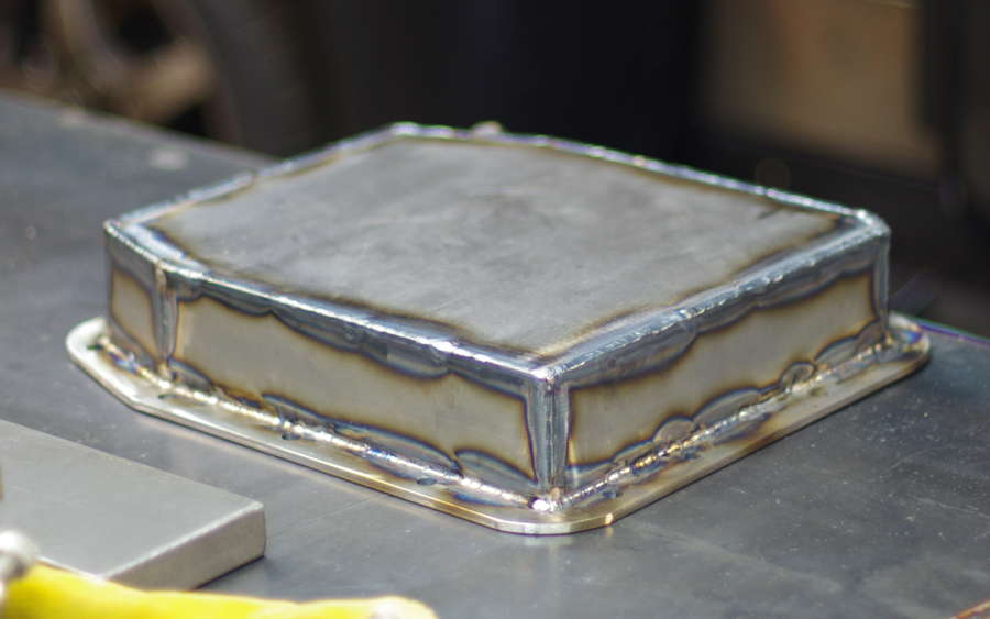
My goal for building this pan was to achieve decent fluid capacity with maximum ground clearance. And to have a pan that would survive if it did accidentally get hit by something (a speed bump etc.)
I built the pan rail and bottom side from 3/16" mild steel. I cut out the inside portion using a plasma cutter and used it for the bottom of the pan. The sides of the pan are 1/8" steel. I clamped the pan rail to a big 2" thick piece of surplus aluminum I have, to keep it flat during tacking together the pieces of the pan. When the pan was complete I leak tested it with water. I did find 3 pin holes I had to fix. Lastly I took it to an engine machining shop where the run the gasket rail on a large belt sander to make sure it was truly flat. They hardly removed any material at all, the rail was pretty flat to begin with, meaning my technique worked as planned. The only issue with this custom pan is that it is quite heavy at 14 lbs. If I did it over I would use somewhat thinner steel plate.
Here are some pan capacity measurements I took:
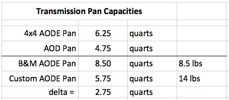
My custom pan capacity (5.75 qts) is not far off of the 'standard' AODE/4R70W 4WD pan that most folks would use (6.25 qts). However, I will lose almost 3 qts capacity in relation to the aluminum B&M pan that I have been using (8.50 qts). To make up for this I have built a custom 3 qt aluminum tank which will be inserted into one of the lines running back to the trans cooler. Thus the total volume of fluid flowing through the system will be the same. More to come on this.
Here is the new custom pan next to the B&M deep sump pan:
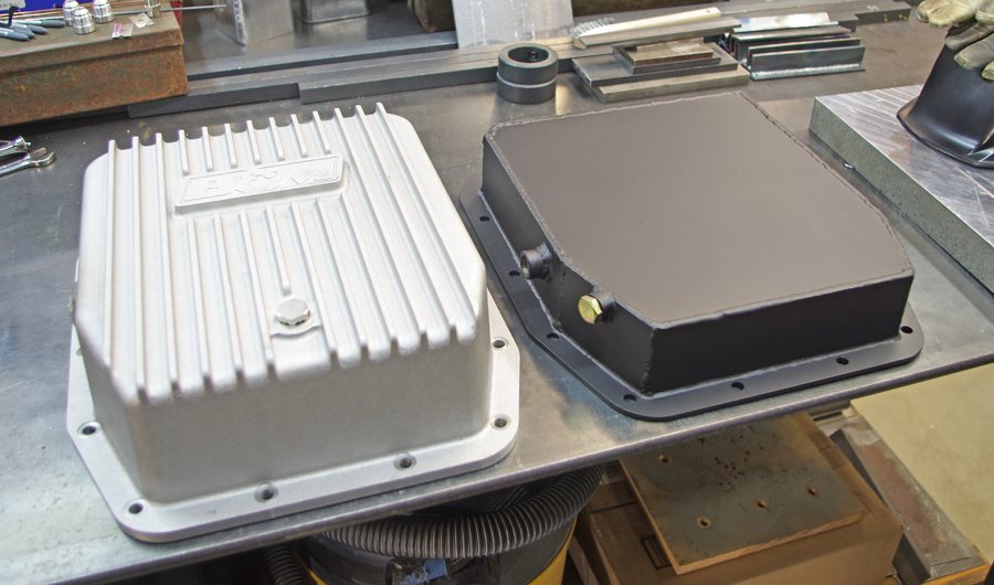
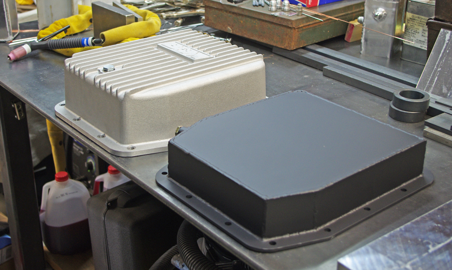
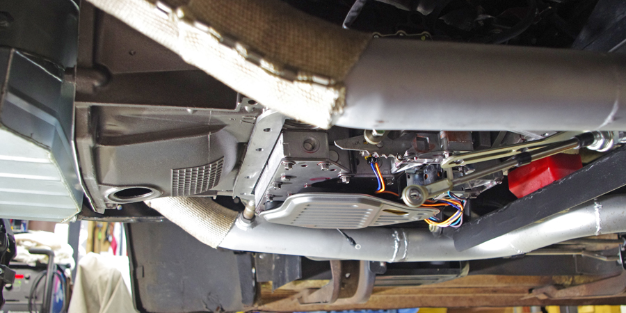
And here is a shot of the bottom side of my truck with just the 2WD AODE/4R70W filter installed. As I see it this determines the limit to how much ground clearance you could expect to gain with any type of pan. You still have to fit this filter. And some of the solenoids hang just about as low so even running without this filter would not gain one very much clearance.
01-10-2017 #100
Starting The Transformation
- Join Date
- Feb 2010
- Location
- El Segundo, CA
- Posts
- 268
Here is the added capacity tank I built to make up for the loss of fluid in the system caused by my low profile transmission pan:
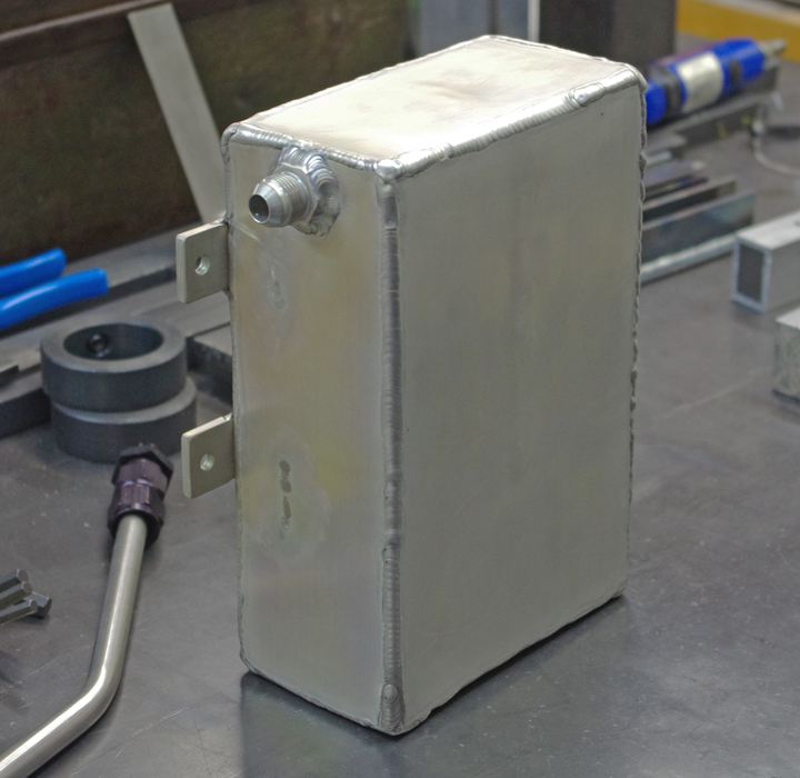
It holds three quarts. I looked around to see if I could find something ready made to fulfill this task, but the closest thing would have been a power steering reservoir. The problem is I wanted the inlet at the bottom of the tank, and the outlet at the absolute top end. That way the tank is guaranteed to fill up completely before fluid moves any further. PS tanks usually have the inlet around the middle of the vertical tank, and the outlet at the bottom.
So I went ahead and made my own to my specs. I added a baffle in the middle of the tank to reduce sloshing under braking and acceleration.
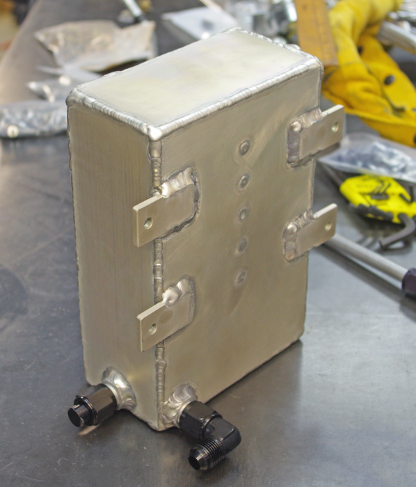
I changed the way I plumbed the hard lines to the tank after I'd built it, which is why it has a second inlet which is capped off.
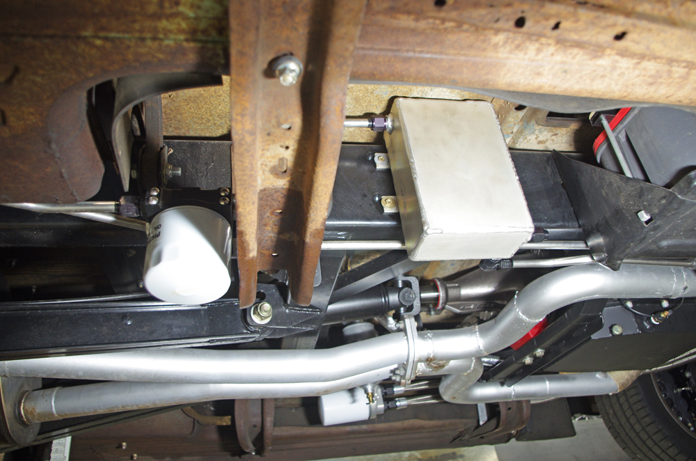
Here is a picture of the tank installed on my frame rail. You can also see the auxiliary transmission fluid filter just downstream of the tank, as the fluid makes its way to the air-to-liquid cooler in the right rear fender.

 Reply With Quote