

Results 61 to 80 of 132
-
12-09-2015 #61

 Registered User
- Join Date
- Aug 2010
- Location
- now In Dandridge, Tn.
- Posts
- 1,301

Looks great with the re-positioned wheel opening. OK, it's not painted yet, so, maybe raise the wheel opening rather than lift the truck? 'cause it looks great down there.
-
12-09-2015 #62 Registered User
- Join Date
- Nov 2006
- Location
- Ma.
- Posts
- 5,560
Beautiful work.
Wayne
Car FINALLY home !!!!!! lol
Project FNQUIK https://www.pro-touring.com/showthre...ghlight=FNQUIK
12-10-2015 #63 Starting The Transformation
- Join Date
- Feb 2010
- Location
- El Segundo, CA
- Posts
- 268
Thanks for the encouragement everyone. Originally Posted by RobNoLimit

Rob, I agree it does look good down low. But it is very low. I have to check more carefully but it's possible that ground clearance is lower than 4 inches. The lowest part of the truck are the 'arms' that protrude from the frame to support the running boards. Next up is the transmission pan! I probably should not have installed the extra capacity B&M pan, though it seemed like a good idea at the time to increase fluid capacity. But it really hangs down there, much lower than the engine oil pan.
Your idea of raising the fender openings is interesting. I'd not thought of that. It may be outside my capabilities, though I'm willing to try it (someone else moved the openings forward). The fenders are pretty trashed so its worth experimenting.
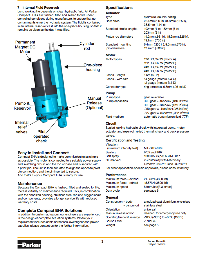
This is one reasons I strongly considered going with air bags. The ability to have a low ride height and raise the truck for parking maneuvers. But I can't warm up to the varying spring rate with ride height. Another idea I think about is using traditional coil-overs but adding electro-hydraulic actuators via rocker arms to vary the location of the upper shock mount in order to change ride height. That way you spring rate is unaltered with ride height changes, though your geometry does change. But the weight and complexity is somewhat daunting. The actuators cost about $500 each. They can certainly support the weight of the truck in order to raise it. And I am pretty sure they "lock-out" when not in use so they can withstand the much larger loads from the shocks while driving.
12-10-2015 #64
Registered User
- Join Date
- Aug 2010
- Location
- now In Dandridge, Tn.
- Posts
- 1,301
Yeah, 4" is pretty low. I try to stay with 5" scrub line for streeters. The actuator idea is interesting. JRI makes a coil-over shock with a hydrolic sleeve for the spring mount, for RH adjustment for driveways and loading. Not sure the cost, but at 2k for four actuators + fab time you have some room to look at. Keep up the good work.
12-11-2015 #65
Starting The Transformation
- Join Date
- Feb 2010
- Location
- El Segundo, CA
- Posts
- 268
OK, that is cool. Just what the doctor ordered. I did not know that was available. I wonder if you can set the ride height for intermediate settings, or if it is only all the way down or all the way up. If they could integrate those with a controller and ride height sensors it would be even better. Originally Posted by RobNoLimit
http://www.jrishocks.com/rideheight/
02-25-2016 #66
Starting The Transformation
- Join Date
- Feb 2010
- Location
- El Segundo, CA
- Posts
- 268
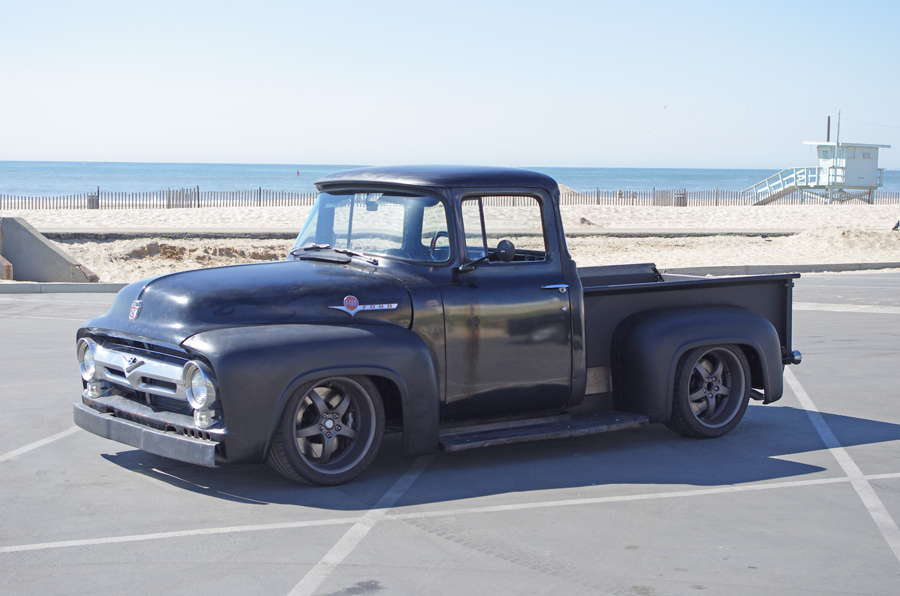
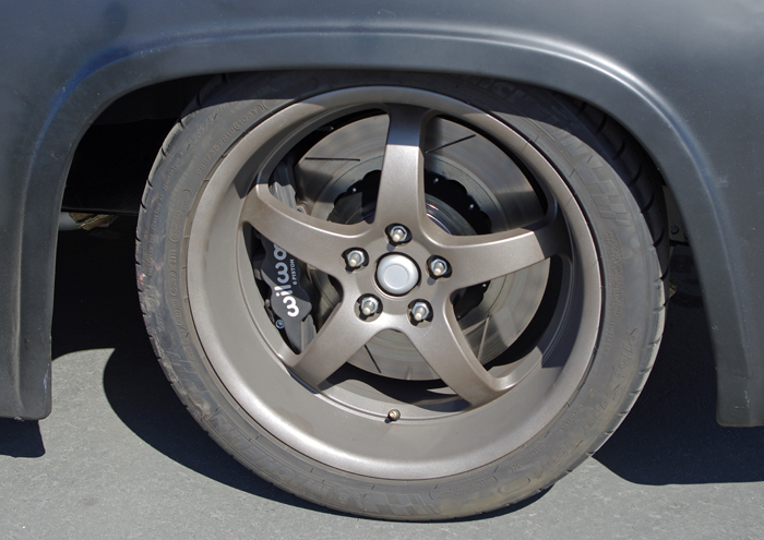
After several teething issues with the transmission and brakes I finally have the truck up and running. The issues with the AODE transmission were (1) contamination in the 1-2 pressure accumulator causing a missed shift to second gear (it felt like it hit neutral in between gears), and (2) my PCS control module wanted to see a later model high resistance TCC solenoid, vs. the low resistance unit installed by TCI. So it kept throwing a code for a wiring problem with the TCC solenoid and would not lock up the torque converter. Now it is working and I've fiddled with the knobs a bit (high and low throttle shift points and shift firmness) and it drives real nice.
The new brakes had a few issues. First the ARP studs I had pressed into the rear axles had a portion near the base that was slightly bigger than the hole in the brake hats. Not by much, the hat would go on most of the way, but not quite all the way. Of course I did not expect this and thus did not recognize it. So I when I shimmed the caliper brackets to center the caliper on the rotor, it was not actually center, since the hat was not fully seated. I should have realized something was wrong when I was torquing the the lug nuts. Even though I hit the right torque value, it felt vague, not solid. The wheel was pushing the rotor hat onto the studs, but not all the way. Then I went out and bedded in my pads and rotors - 20 or so very hard stops. One can imagine that no good came of that. The left side was bad, wheel destroyed, rotor hat destroyed, wheel spacer destroyed, studs loose in the axle, requiring new studs and re-drilling the axle. The right side came away better. It was not until I was putting everything back together the second time that I finally saw the problem. A quick pass through each hole in the brake hats with a clearance drill and all was well.
I originally tried to see if I could get away with running race pads on the street. The pads worked very well, with good friction and low required pedal effort. But they would squeal like crazy during slow stops, there was no way I could tolerate it. The dust production was also amazing, though I could have lived with that on my crapper truck. I swapped to performance street pads, which don't feel as good but are quiet (and less dusty). I also swapped out the 3/4" bore master cylinders for 5/8" bore units to reduce pedal effort (but accepting greater pedal travel in the process).
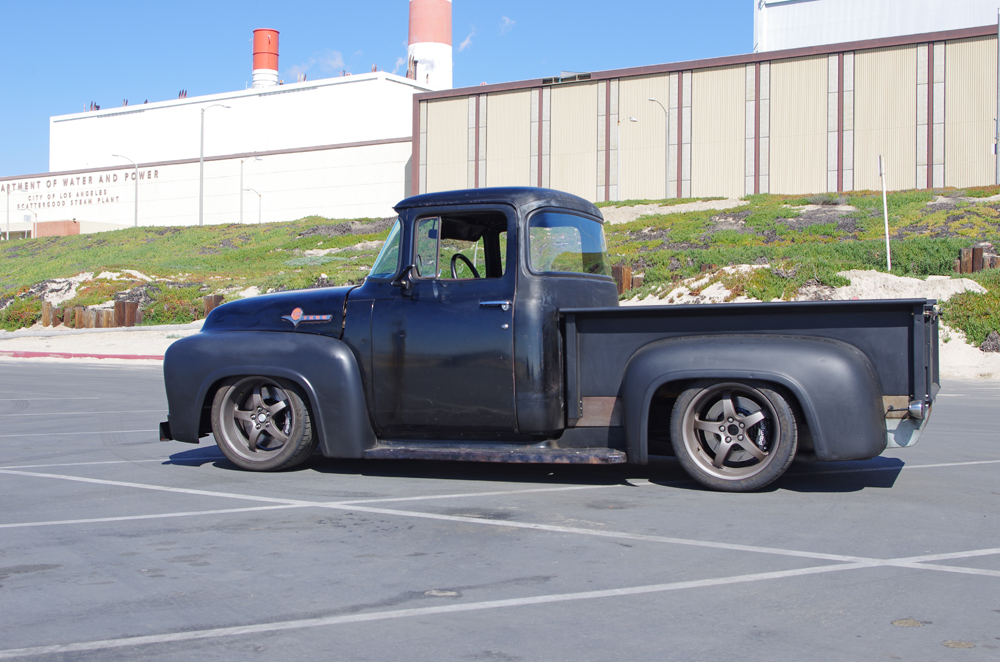
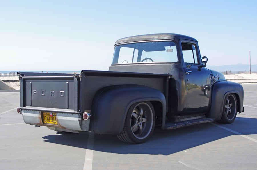
Here are a few pics I took today:
Gustave
02-25-2016 #67
Registered User
- Join Date
- Dec 2010
- Posts
- 708
Dude, you've nailed it thus far. It kind of screams: fast and highly capable, but with neverending mad tinkering, so as to always demolish junior's drift-motivated mess . . .
02-26-2016 #68
Registered User
- Join Date
- Apr 2011
- Posts
- 165
Hey Gustave
Are those stock rear view mirrors? If not what are they?
02-26-2016 #69
Starting The Transformation
- Join Date
- Feb 2010
- Location
- El Segundo, CA
- Posts
- 268
Thanks, yes, that's been the goal. I'll be hitting some auto-crosses at California Speedway this summer. Originally Posted by rustomatic
02-26-2016 #70
Starting The Transformation
- Join Date
- Feb 2010
- Location
- El Segundo, CA
- Posts
- 268
Originally Posted by hotrod56
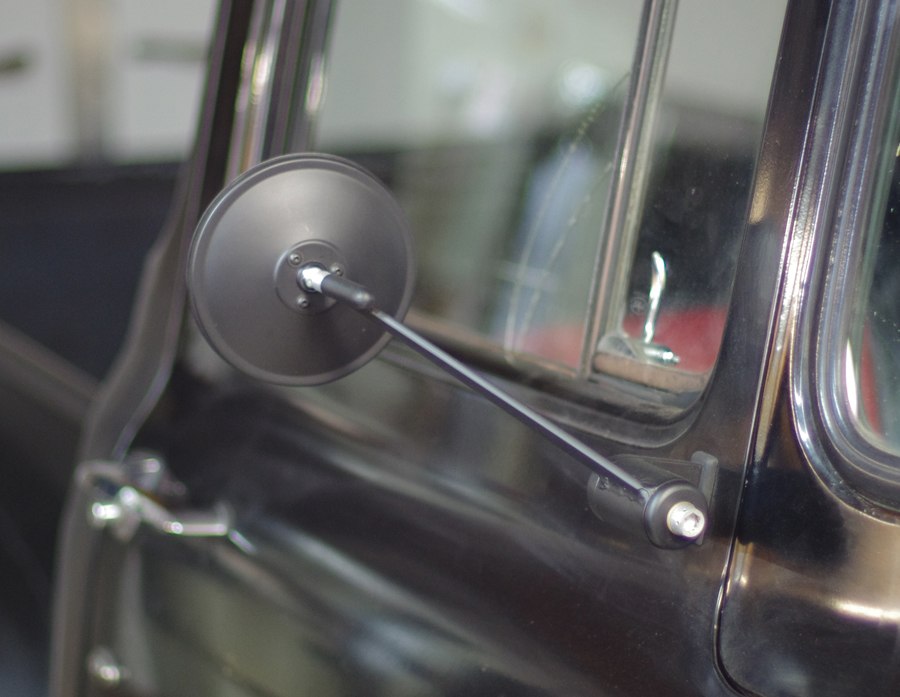
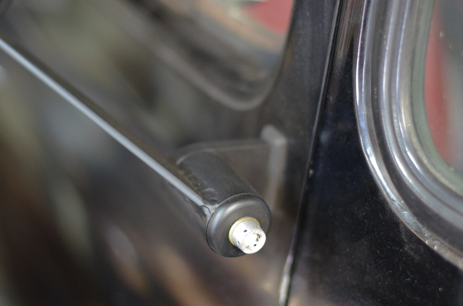
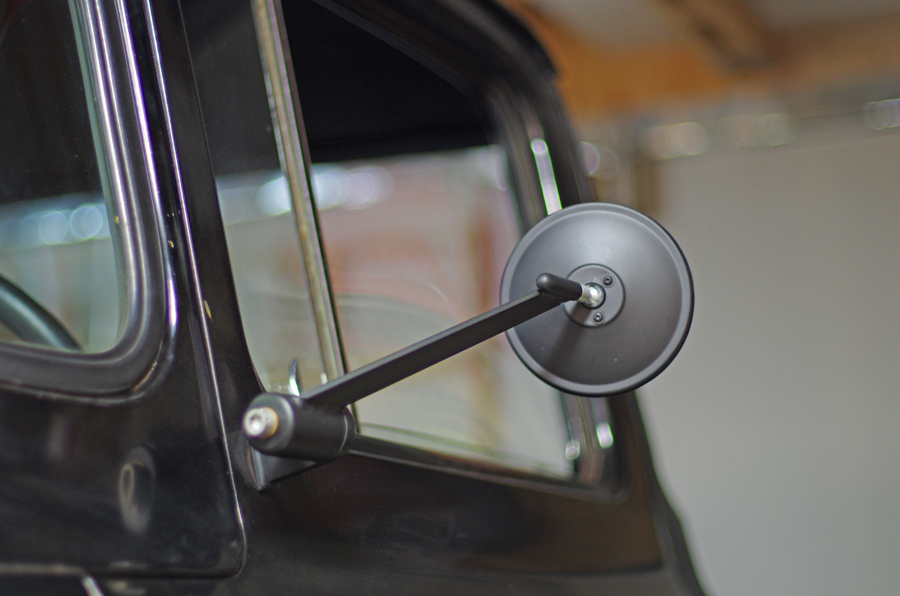
I made the mirrors myself. The stock mirrors are very heavy, so they tended to vibrate a lot since they are mounted to a not so stiff portion of the door. My mirrors are much lighter and stay steady. Also, the F100 has a notorious feature where the passenger side mirror is blocked by the post between the vent and main windows. So I moved the mirror further back.
I bought the actual mirror portion, very cheap, like $10 each. Then made the rest based on style. The stalks are 4130, the bullets are tubing that I rounded and tapped. The base uses a big washer that I ground a rounded edge on. The bolt is surplus airframe.
Gustave
02-26-2016 #71
Registered User
- Join Date
- Apr 2011
- Posts
- 165
very cool!
02-26-2016 #72 Registered User
- Join Date
- Jul 2011
- Location
- Prescott, AZ
- Posts
- 206
The attention to detail in this build is amazing!
02-27-2016 #73
Starting The Transformation
- Join Date
- Feb 2010
- Location
- El Segundo, CA
- Posts
- 268
Another thing I changed recently is my electric cooling fan. I control the fan via the ECU. It puts out a pulse width modulated (pwm) signal to a solid state relay based on coolant and air temperature. This way I can change the duty cycle to run the fan from say 30% speed to full speed as the coolant gets warmer. It's not all or nothing (full speed or off).
I had been running a Spal fan. This was my second Spal fan, the first one I replaced due to vibration. I figured it had gone out of balance. I installed the new Spal fan and it did the same thing. So now, somewhat dismayed with the Spal fans (even though my gut tells me they are the best) I swapped over to a Derale fan. And it also vibrated! At this point I'm thinking it has to be more than a coincidence. Something else must be going on.
I posed the question to the gurus at the Tuning Forum. It was suggested that I try a different frequency for the PWM signal. I had not realized it was adjustable within my ECU software, but it was. So I played around with it. Originally it was set to 20 Hz. I moved it up and down finally settling on 300 Hz (the maximum value). And voila, my fan was smooth as silk right down to 10% duty cycle. Moral of the story is that both Spal fans are probably just fine, I replace them unnecessarily. Luckily I still have them so can use them in the future if needed. They are clearly better made (Italy) than the Derale fan (China it appears).
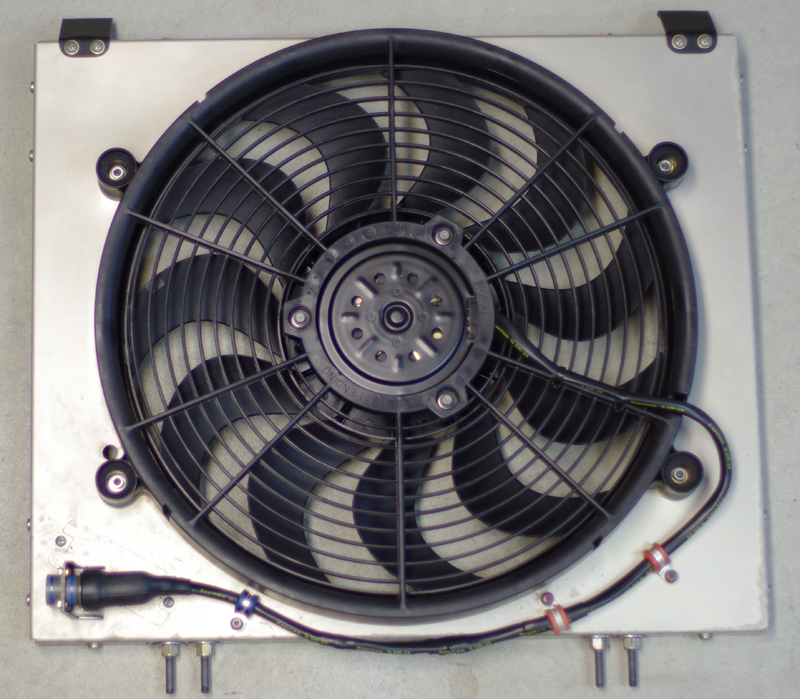
Here is a pic of the Derale fan, the shroud it came with and the wiring I redid to allow for a Mil Spec connector. Hidden in the wiring is a flyback diode which prevents the SSR (solid state relay) from being toasted by the fan motor as it is turned on and off.
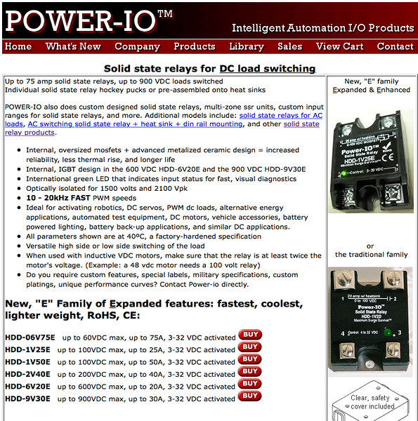
If anyone is interested, this is the SSR I used:
Gustave
02-28-2016 #74
Registered User
- Join Date
- Sep 2011
- Location
- Southern Ontario
- Posts
- 640

You do nice work Gustave. Can you show the cooler in the back fender from the front, your giving me a good idea!
02-28-2016 #75
Starting The Transformation
- Join Date
- Feb 2010
- Location
- El Segundo, CA
- Posts
- 268
I assume you mean this? Photos from inside the fender are further back in this thread. Originally Posted by Peter Mc Mahon
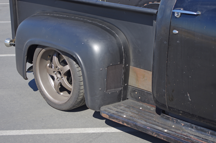
Forgive the butchery on the rear fenders. This was done by a prior builder who had lost interest in the project and committed the sin of sins, a lap joint. I will get to fixing this eventually.
Gustave
04-04-2016 #76
Registered User
- Join Date
- Jan 2016
- Posts
- 1
All I have to say is WOW!! Awesome job and some really great inspiration!!
04-22-2016 #77
Starting The Transformation
- Join Date
- Feb 2010
- Location
- El Segundo, CA
- Posts
- 268
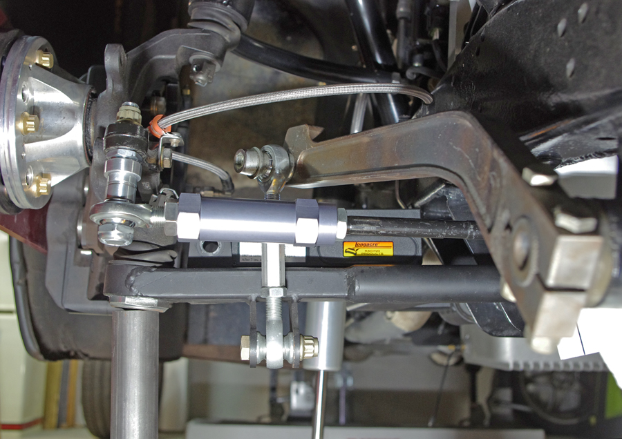
After re-building my front suspension I have finally gotten around to measuring my bump steer. I used a Longacre bump steer gauge which uses a single dial indicator instead of two. Makes it a little easier to read the numbers. It took some fiddling of the gauge to get it to work on my truck. I had make new longer arms to get the gauge to reach up high enough, since I prop my truck up pretty high on jack stands when working on it. I also had to make a few new parts to get the roller bearing and dial indicator to reach past my wheel studs. I locked the steering using ratchet straps going either direction off of the steering wheel to my seat base, which worked well and kept me from chasing my tail while taking data. Here is a pic of the test setup:

I expected my bump steer curve would look pretty bad, and it does:
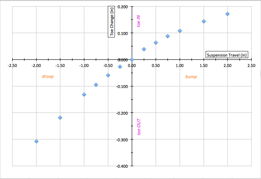
You can see that at 1 inch of bump travel the right front wheel toe's in almost 1/8". If both wheels hit a bump at the same time and compress 1 inch each, that would be 1/4" of total toe in! And that is only at the gauge, which you can see is not as wide as a wheel or tire. I usually measure toe at the wheel lip. Some measure it at the tire surface. Since where you measure toe affects the result you get, my data above would look even worse if I adjusted it to reflect measurements at the wheel lip.
During inspections of the front end I discovered at least one reason that my bump steer is bad. My inner tie rod ends are nowhere near a line drawn between the upper and lower control arm inner pivot points. My rack is way too short relative to where the the suspension pickup points are located on the frame. I guess I should have checked this a long time ago, but it just never occurred to me since the inner tie rod ends are hidden under the rack bellows.
Doing some research I quickly learned that this is not an uncommon problem for folks using Mustang steering racks. And there are rack extension spacers available to help redress the problem. They fit between the rack and the inner tie rods and effectively lengthen the rack (push the inner tie rod pivots outwards). I've ordered some 2" spacers (per side) which looks to be close to what I need. I will install those and remeasure the bump steer and then decide if anything else can be done to make things better.
04-29-2016 #78
 Registered User
- Join Date
- Feb 2013
- Posts
- 1,557
Nice! Keep it updated :D
05-03-2016 #79
Starting The Transformation
- Join Date
- Feb 2010
- Location
- El Segundo, CA
- Posts
- 268
In my last post I was busy measuring my bump steer. I had come to the conclusion that my steering rack was "too short". In the sense that the inner tie rod ends were well inboard of an imaginary line drawn through the inner pivots of the control arms. There is a ton of info about this on the web. See this picture of an "ideal" suspension for minimal bump steer:
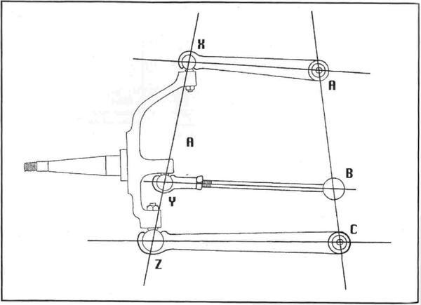
In my original configuration the inner tie rod (B) was about 1.5" to the right of where it is shown in the diagram. To make things worse, the outer tie rod end (Y) was to the left of where it is shown in the diagram above. So the total tie rod length was too long.
The location of the outer tie rod end I estimated from the Wilwood CAD drawing for their pro spindle:
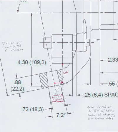
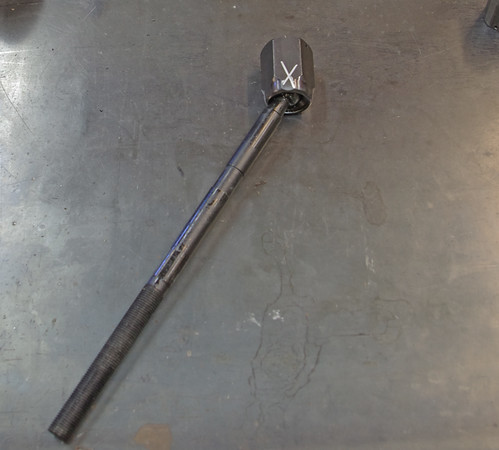
This drawing has proved very valuable in sorting out the front end geometry. One variable I had to determine was the actual location of the outer tie rod pivot. It is basically a ball in socket design, so where is the center of the ball relative to the steering arm? Not easy to tell just by looking at it. I came up with another estimation technique. I moved the tie rod to the two extremes of its range of motion and then visually drew a line on the socket matching the centerline of the tie rod. Where the lines cross is the center of the ball:
To visualize the centerline between my control arm inner pivots I made a cardboard template. I cut two holes which fit over bolt/nut heads on the pivots, and drew a line through the center of those holes:
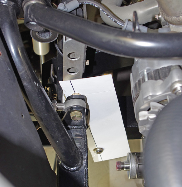
All these measurements are tricky and not perfectly accurate on an assembled truck. But I did my best. Having a bare frame on a table would make it all a lot easier. But the challenge of finding the exact center of ball joints and rod ends remains. It is one thing to design the perfect suspension using software. It is another thing to be able to "build to print" as they say.
So, back to the steering rack spacers...
I ordered some from Speedway, not totally sure they would fit until I saw them in the flesh. But fit they did on my Mustang PS rack. Here they are:
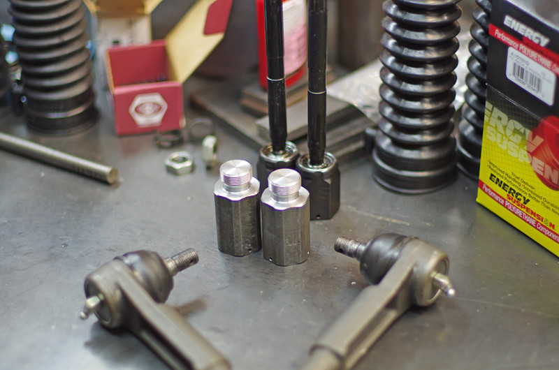
Full of optimism, I installed one of the rack spacers and proceeded to re-measure my bump steer. The results were surprising. I'll cover them in the next post.
05-04-2016 #80
Starting The Transformation
- Join Date
- Feb 2010
- Location
- El Segundo, CA
- Posts
- 268
Well, the result of adding the rack spacers was initially disappointing. The bump steer was mostly the same, and even worse as the wheel moved further into bump! I was completely taken off guard by this at first. I just sat there on my inverted milk crate staring at the front suspension wondering how moving the geometry in the right direction could degrade bump steer even further.
Eventually I snapped out of my stupor and started thinking logically like the engineer that I am. And I came to an interesting conclusion that I've not seen mentioned in the many write ups online about bump steer. It is frequently stated that two conditions must exist for minimal bump steer:
1. The tie rod must be of a length such that it extends from the lines intersecting the outer ball joints of the control arms and the inner pivot points of the control arms (see pic earlier).
2. The tie rod must point to the instant center created by the upper and lower control arm.
My conclusion is that #2 is much more important than #1.
I convinced myself of this with some simple sketches, but I won't dwell on it here.
My tie rods are located very close to the lower control arms (and far away from the upper control arms). So for the tie rod to point to instant center it made sense that it should be at somewhat close to the same angle as the lower control arm. But it wasn't that way at all. My outer tie rod ends needed to move downward to get the right angle.
Enter the bump steer kit. I bought one from Summit. I installed it on one side and as a first cut mounted all of the provided spacers above the rod end (which replaces the outer tie rod). With this configuration I re-measure the bump steer. Low and behold, things got a lot better.
From reading around on the web about bump steer, I had a loose goal of not exceeding 0.020" of toe change within the first inch of bump travel. However this initial try with the bump steer kit did not quite achieve this criteria. I've got a box of assorted spacers so I used some to increase the downward offset of the outer tie rod end a bit more. Then I remeasured the bump steer one more time. And the results once again surprised me.
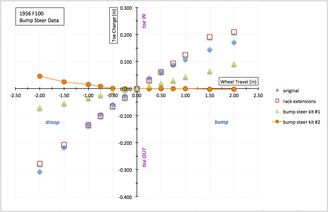
Not because they were bad, but because they were unbelievably good! I started jacking the suspension up to 1/4" of bump. The dial indicator showed 0.000" of toe change. I figured something must be wrong so I lower the suspension and re-zeroed the indicator and repeated the procedure. The second time around at 1/4" bump the indicator still registered 0.000" of toe change. Baffled, I moved up to 1/2" of bump travel. Still the dial indicator read 0.000". At this point I figured something must be way wrong with my setup so I checked everything carefully, re-zeroed and started over. This time I got up to 3/4" of bump travel and still the dial indicator read 0.000" of toe change! This continued up to 1 full inch of bump travel! Only at 1.5 inches of bump travel did the toe change at all, and then only very slightly. I somehow bumbled into a very stable suspension setup for bump steer. I repeated the test enough times to convince myself it is not a fluke.
The results for droop travel are not quite as magical, but nonetheless quite good. Meeting my original goal of 0.020" of toe change in the first 1" of wheel travel.
Needless to say, I decided that this was good enough. Here are a few pictures of things.
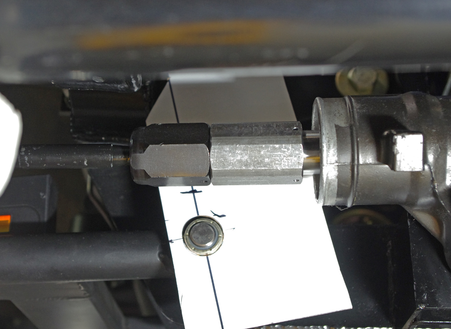
The following pic shows the rack extension and how it move the inner tie rod pivot outwards:
This picture shows the tapered stud that installs where the tie rod end normally goes:
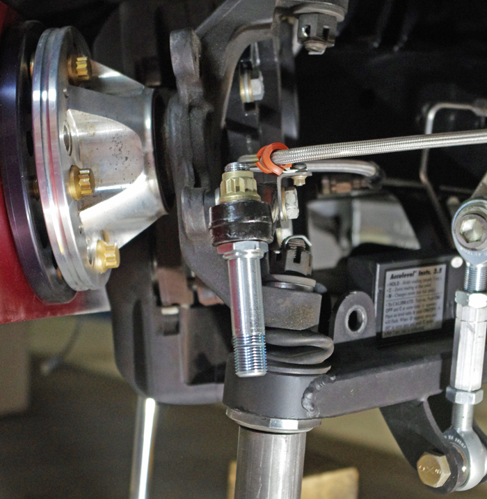
Here is the same stud with spacers and tie rod attached in the final configuration:

In this similar photo you can just make out the upper control arm. This is with the suspension at ride height. The angle of the tie rod is close to the angle of the lower control arm, which turned out to be the right solution:
Last but not least, here is the bump steer data. The Orange data series is the final configuration. You can see by the near horizontal shape of the curve that the toe changes very little with changes in wheel travel:

 Reply With Quote