

Results 61 to 80 of 112
-
11-21-2012 #61

 Registered User
- Join Date
- Dec 2007
- Posts
- 284
OK some conclusions.
It appears for my current setup to work I would need to shorten the steering arms, replace upper control arms and modify the lowers.
Alternatively I can get wheels with 4 7/8" offset, then use 2.5" shorter upper and lower control arms then I believe the spindles would work.
This would decrease hub-hub width to 50" which eliminates most power steering racks. I think the woodward rack will work with 50".
I guess thats what I need to determine next, I am trying to keep power steering, that is part of the reason for this exercise.
Thanks for all the help so far!
-
11-21-2012 #62
 Registered User
- Join Date
- Oct 2009
- Location
- New Derry, PA
- Posts
- 1,265

Keep in mind that if you go with a lower offset wheel, the tire will "swing" further toward the fender as you steer. Make sure you have adequate outside clearance if you go that route.

Ray Kaufman - Wyotech Chassis Fab and High Performance Instructor. Words of Wisdom from an old master... at Asylum Custom Interiors website
-
11-21-2012 #63
Registered User
- Join Date
- Sep 2005
- Location
- Woodstock, Ga
- Posts
- 695
I was trying to find one of my notebooks I have of suspension measurements and drawings and it seems to be boxed up somewhere. I will try to sort through some of my cad files to pull the measurements, but you may be able to find some of the information you need in the links below if your interested in the c5/c6 suspension parts at all.
Looks like the upper arm is 8.55 and the lower is 15.96
https://www.pro-touring.com/showthre...n-measurements
http://www.vettemod.com/forum/showthread.php?t=8387
http://www.gt40s.com/forum/gt40-tech...int-taper.html
Robert
-
11-22-2012 #64
Registered User
- Join Date
- Dec 2007
- Posts
- 284
Hey man thanks for the links, just went through those.
I had found those dimensions for the C-5 arms, looks like that gives about 140%
difference for the set.
On the S10 control arms its closer to 125%.
I came across this last night, was a very interesting blog I read the whole thing
last night finished it about 3am
http://www.rhoadescamaro.com/build/?m=201211
-
11-22-2012 #65
Registered User
- Join Date
- Sep 2005
- Location
- Woodstock, Ga
- Posts
- 695
Rick, are you able to make arms? you could always use the vette knuckle and make both or one of the arms. There are also a few companies that might be able to make you custom length arms.
If you do go the blazer spindle route, and need to get lower, I have a new pair of 2" drop spindles with new sealed hubs and corvette brakes bracket I bought several years back.
Robert
-
11-22-2012 #66
Registered User
- Join Date
- Dec 2007
- Posts
- 284
[QUOTE=RS_Customs;951658]Rick, are you able to make arms? you could always use the vette knuckle and make both or one of the arms. There are also a few companies that might be able to make you custom length arms.
Hey robert, ideally I would like to get all these dimensions put in a suspension analyzer program by someone who is familiar with it to discuss what it says and
go from there. I don't have a source for someone to make arms but have not researched that route yet, what about you?
At this point no decision on any parts, need to find correct dimensions then see what I need to put it together, where that tie rod end needs to be etc etc,
I am not sure what specifications are still needed to plot this all out
I think after reading the rhoades build I want 5-10 degrees of caster and camber and
I believe the control arm ratio should be closer to 150 than 125 which would give me
control arm lengths like 14 inches on the bottom and 7-8 inches for the upper.
The vette lower arms are almost 16 inches with an upper around 8.5, I don't
believe I have room for 16 inch lower control arms and have room for exhaust
and steering.
-
11-24-2012 #67
Registered User
- Join Date
- Dec 2007
- Posts
- 284
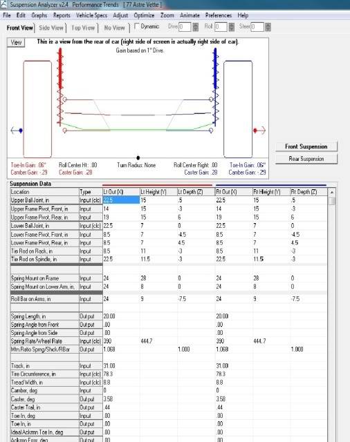
OK so I downloaded the demo and put some points in....
-
11-24-2012 #68
Registered User
- Join Date
- Dec 2007
- Posts
- 284
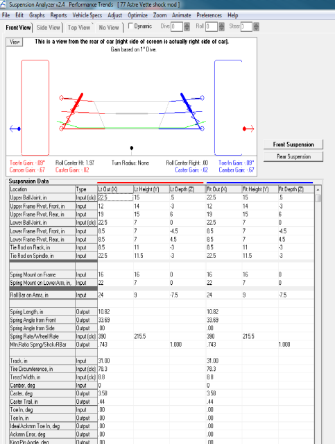
In this plot I basically narrowed the 2001 Corvette specs 7 inches. In doing this I lost 3.5 inches
off of each lower control arm thus changing the effective rates. Did not seem to have a huge
difference.
LINES EDITED WERE:
Upper ball joint
Upper frame pivot front
Upper frame pivot rear
Lower ball joint
Lower frame pivot front
Lower frame pivot rear
Tie rod on Rack
Tie rod on Spindle
Track width
Tread width (for larger tire)
Camber

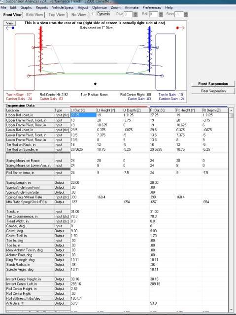
2001 Corvette specs
-
11-24-2012 #69
Registered User
- Join Date
- Oct 2009
- Location
- San Diego, CA
- Posts
- 226
Saw this thread as a link referrer...
If you're going this clean sheet man, why not put the engine behind you? Mate it up with a G50 or Sierra transaxle depending on power levels. Then you'll have all the room to do anything you want with the front suspension, manage cooling better, and best of all - you'll have a much lower polar moment and a much higher static rear weight distribution, than any of these crappy old musclecars people are building. All these builds with a bajillion HP going through crappy 200TW tires, ugg - at least with ~60% static on the rear 345 tires, you'll have a chance of putting some of it down.
Also, I wouldn't use those parts - the circle track catalogs have lots of stuff to choose from that isn't as expensive, and will offer a lot of adjustability to help with tuning down the road.--Jason Rhoades
http://www.rhoadescamaro.com/build
-
11-25-2012 #70
Registered User
- Join Date
- Dec 2007
- Posts
- 284
Hey thanks for the reply. I suspect most of this was sarcasm, since this is a vega after all, not another high dollar
first/second gen camaro build. Regardless I respect what you are saying after reading your blog and the CVD series.
This is all Marcus at SC&C's fault.(totaling j/k) My plan was to just bolt on some control arms and fit some larger tires, but then
after speaking with him about the pitfalls of the stock front suspension, well here we are.
Any advice you have to offer here would be greatly appreciated, outside of moving the motor to the back of the car.
-
11-30-2012 #71
Registered User
- Join Date
- Dec 2007
- Posts
- 284
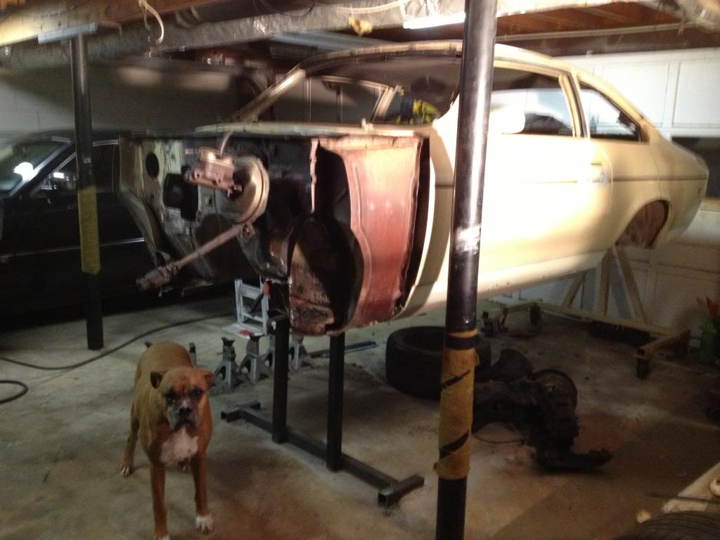
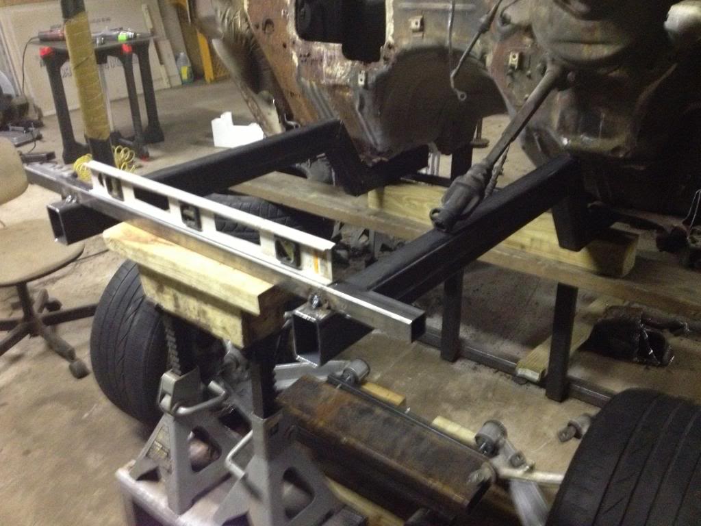
Hey Ray, I was looking at this picture again, what I notice is it looks that that truck has wheels with Originally Posted by exwestracer

4.5 inch backspacing. Is that correct?
If I set this up with the Vette Wheels with backspacing of 7.38 inches that will gain me 5.75 inches
to move the control arms out, about 2.75 inches further out on either side from what is in these
pictures right?
Do you recall what the outside frame width was on the S10 chassis?
Thanks.
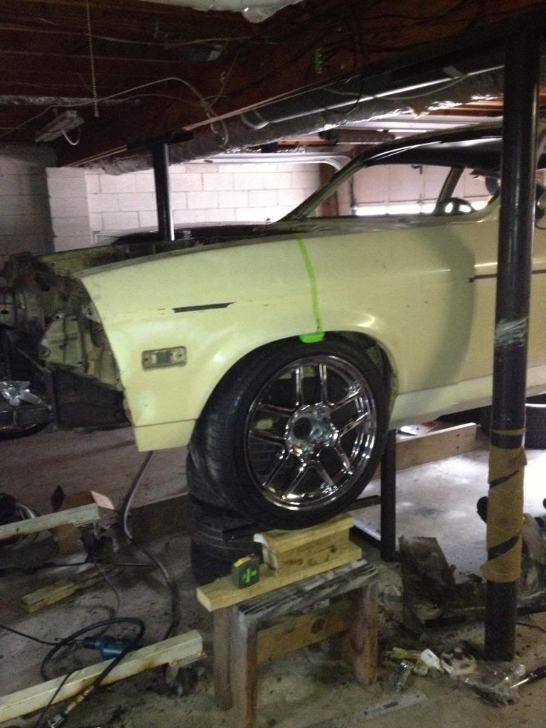
A pic to show I am getting it read for new frame rails...
-
11-30-2012 #72
Registered User
- Join Date
- Oct 2009
- Location
- New Derry, PA
- Posts
- 1,265
Sorry, I don't remember ANY details about that truck, other than it was a real PITA to package everything.
Looking at the first picture, the frame support fixtures are almost exactly 1/2 way out on the frame bench crossmember. I measured one and they are 49 1/2" wide, so that would put the frame rails somewhere ABOUT 24-25" on center. Hope that helps.
Ray Kaufman - Wyotech Chassis Fab and High Performance Instructor. Words of Wisdom from an old master... at Asylum Custom Interiors website
-
12-02-2012 #73
Registered User
- Join Date
- Dec 2007
- Posts
- 284
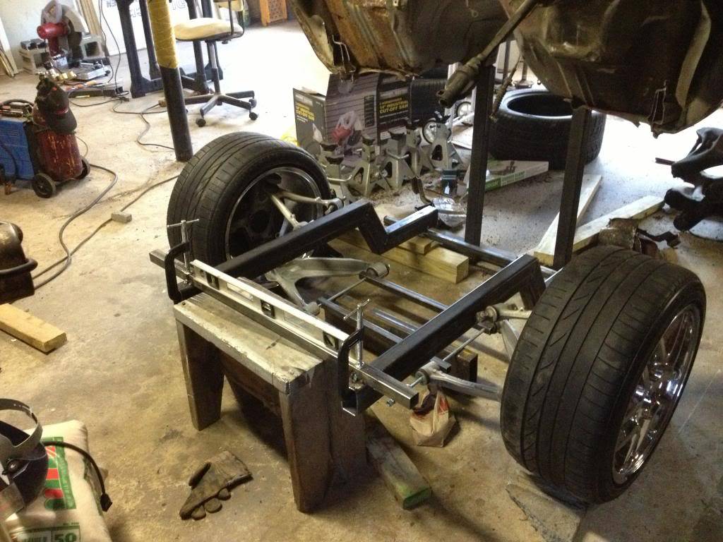
Picked up my C5 suspension pieces and did a little more measuring, cutting, welding and this is where I got...
-
12-02-2012 #74
 Registered User
- Join Date
- Sep 2007
- Location
- Buford, GA
- Posts
- 923
I'm sure this is a silly question, but you do plan on tying the front of the sub back up to the top of the firewall, right?
Adam
1985 S10 - LT1 + T56
1964 Chevy II 4-Door - LS1 + T56
-
12-02-2012 #75
Registered User
- Join Date
- Sep 2007
- Location
- Buford, GA
- Posts
- 923
Okay, here is what seems to be a logical next step. I think you should make a drawing from the SIDE of the car plotting the points you know about where the UCA's and LCA's should mount. At least in the "X" and "Y" direction. Don't even worry about the "Z" direction for my example. Doing so you will be able to locate the height (top and bottom elevation) of your frame rail. Obviously you don't want to have your framerail too high and not be able to get your UCA mount low enough to locate it correctly.
Adam
1985 S10 - LT1 + T56
1964 Chevy II 4-Door - LS1 + T56
-
12-03-2012 #76
Registered User
- Join Date
- Dec 2007
- Posts
- 284
The steering rack should be here this week, also ordered some threaded tube ends for the lower control arm mounts, I need to get the upper
control arm brackets made so I can get those mocked in. The place I have been getting steel from has a laser cutter if I can send them a dxf
or dwg file they can cut them out for me.
The pictured with the control arms clamped to the frame is roughly at ride height, 6 inches from rails to ground, top of kicked up rail 15.5 inches
if I remember correct. Concern now is if there is really room for the motor between those rails....
-
12-03-2012 #77
Registered User
- Join Date
- Oct 2009
- Location
- New Derry, PA
- Posts
- 1,265
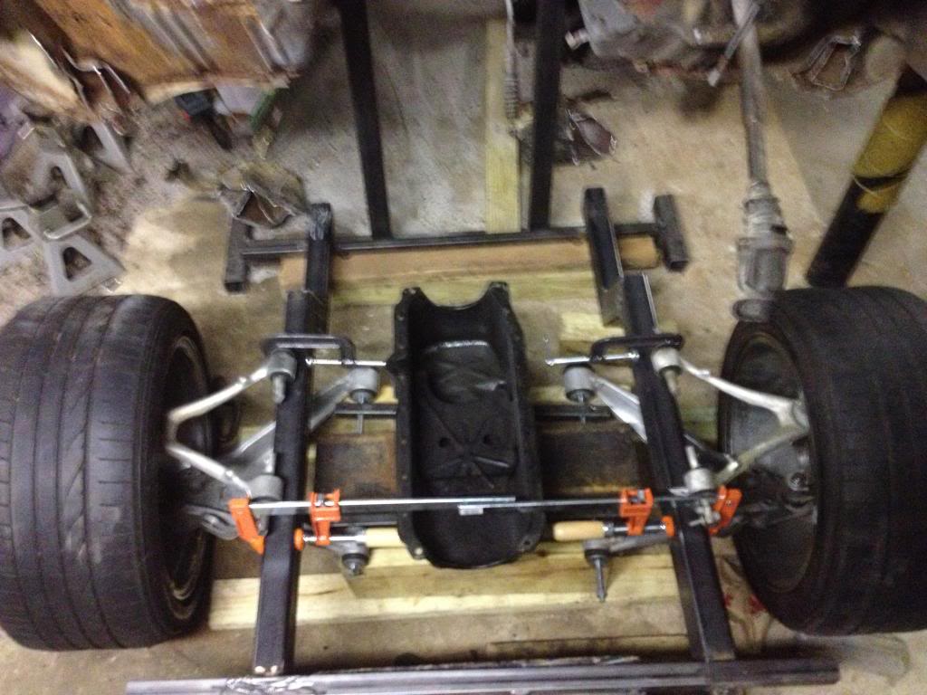
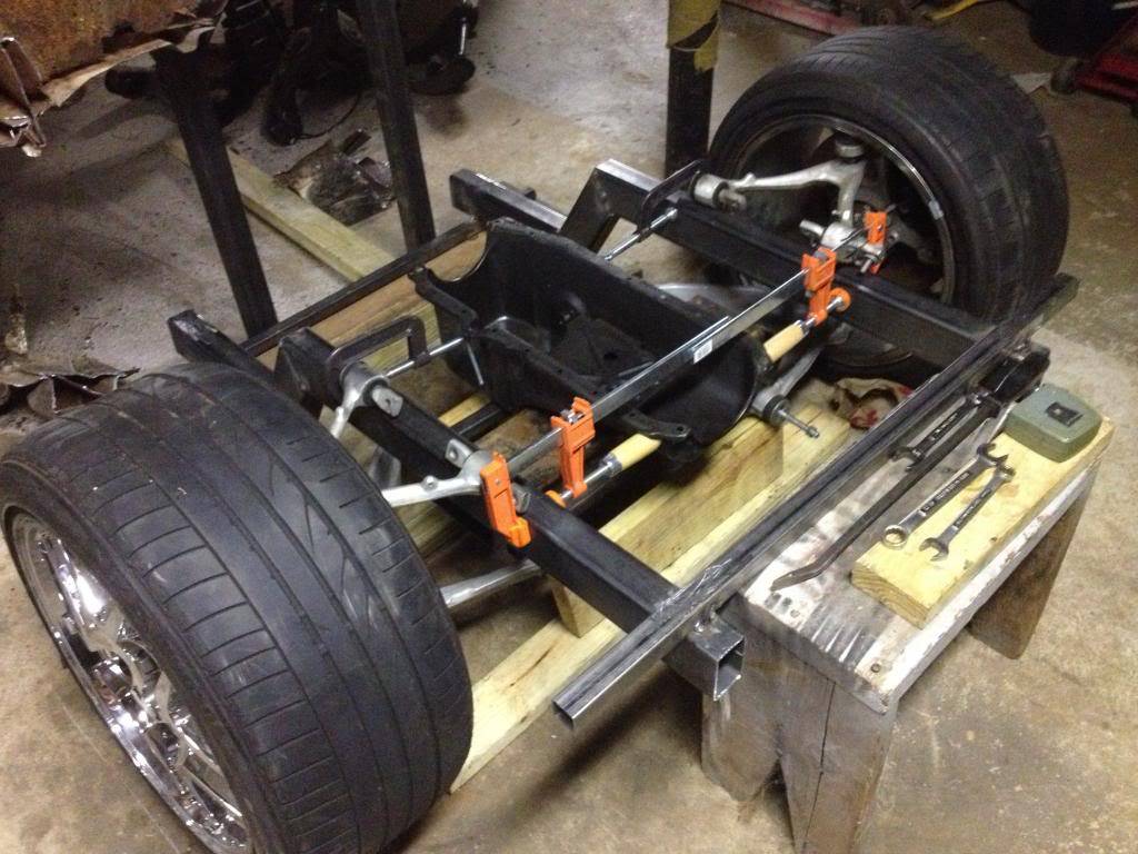
In FRONT view, is the LCA mounting bolt level with the lower ball joint center? A straight on front picture of your mockup would help to see the relative angles.
Ray Kaufman - Wyotech Chassis Fab and High Performance Instructor. Words of Wisdom from an old master... at Asylum Custom Interiors website
-
12-03-2012 #78
Registered User
- Join Date
- Dec 2007
- Posts
- 284
More or less, according to performance analyzer the LCA front and rear pivots are not level and the ball joint is 6.375 inches from ground. That is a 2x6 channel those threaded rods Originally Posted by exwestracer
are sitting on. so roughly 6.25 ish i would say, I am just mocking things up to see if it will work or not, taking measurements etc. I will lower the frame back down
and do take some pics with measurements...
In looking at the A arm geometry from the factory there is 12.625 inches between front upper and lower pivots and 10.625 inches between the rear upper and lower pivots
Also, the lower arm is pitch up from front to back and the upper is pitched down from front to back.
Factory spec is nine degrees of caster, I would like to lower that to 6 degrees so I was thinking of raising the rear upper pivot about .46 inches, to decrease
the caster, is there an adverse condition I will be inducing by doing this? Do I need to move something else in addition?
I used to do front end alignments, part time job at Sears when I was in school, so I know a little about front end geometry but this is getting deeper....
-
12-03-2012 #79
Registered User
- Join Date
- Oct 2009
- Location
- New Derry, PA
- Posts
- 1,265
Raising the pivot won't change the static caster. It will change the amount of front brake anti-dive and caster GAIN. Shifting the UCA mounts forward in the chassis will reduce the static caster.
Ray Kaufman - Wyotech Chassis Fab and High Performance Instructor. Words of Wisdom from an old master... at Asylum Custom Interiors website
-
12-03-2012 #80
Registered User
- Join Date
- Dec 2007
- Posts
- 284
ok, so armed with a little info looks like if i move the upper control arm mounts forward .375 inches it should lower the caster to approximately 6 degrees.
I was thinking, when we did alignments of course we could not move the pick up points forward or backward or up or down, to add subtract caster you
had to stagger the upper shims if I remember right.
I think its coming together, I should have a rack in this week so thats the next and probably biggest part of this puzzle to come.
Thanks for all the help. I am trying to push my knowledge this is the biggest project I have taken on.
Rick
-

 Reply With Quote


