


Results 81 to 100 of 138
Thread: 3rd gen Z28 track day build
-
04-29-2016 #81
 Registered User
- Join Date
- Jun 2015
- Location
- kent,ohio
- Posts
- 128

So I got the engine/trans back in the car, installed the headers and raised it up as high as the firewall would allow. Engine came up 1 1/2" and raising the trans 1" got the driveshaft back inline with the rear axle. The engine/trans angle down at 2 degrees and pinion angle is also 2 degrees down. I can raise lower pinion quite a bit if needed and can also raise trans one or two degrees if needed.
Trans vent barely clears trans tunnel.
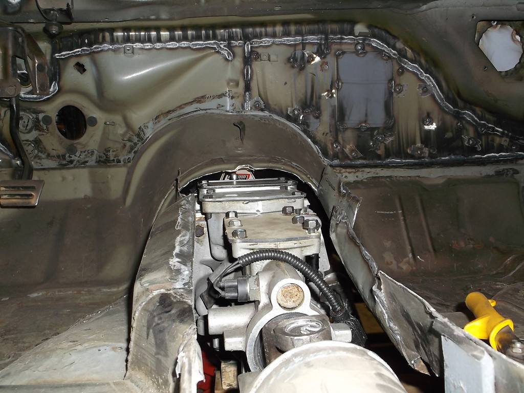
Top of TKO is actually above the factory tunnel. I will be making a new tunnel from 20ga sheet steel.
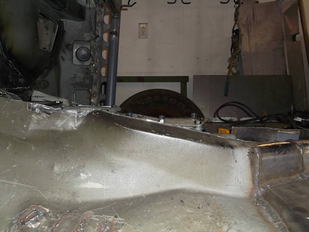
engine now sits 1 1/2" off k-member
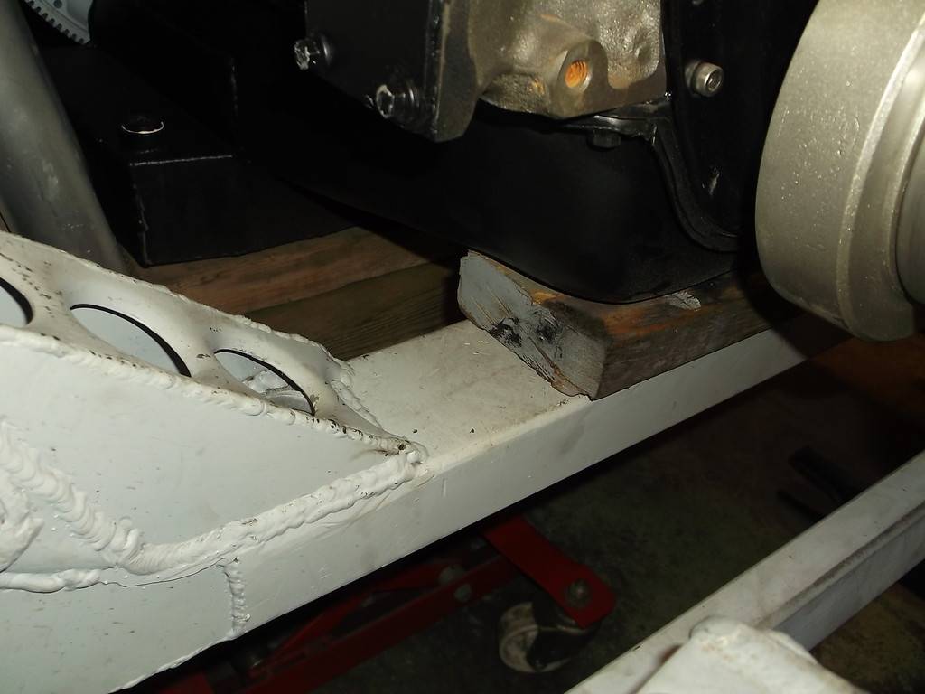
I will have to extend the motor mounts.
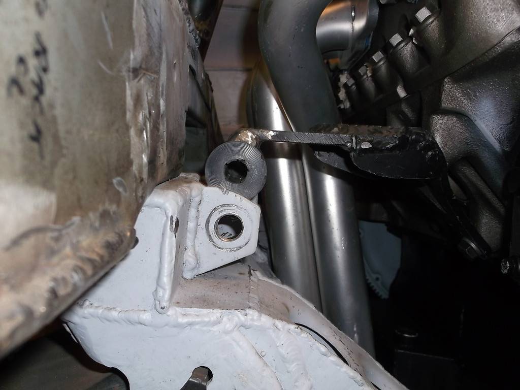
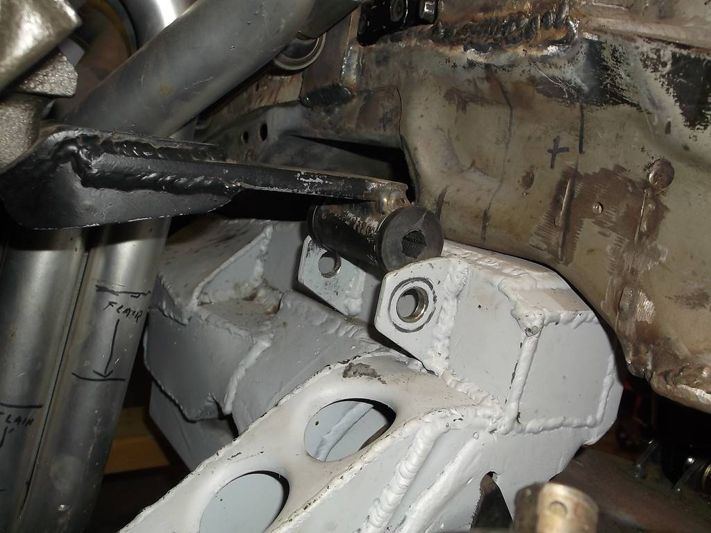
I was able to raise the trans xmember with pieces of 1x1 angle iron. I had to massage the floorboards a little to clear the exhaust humps.
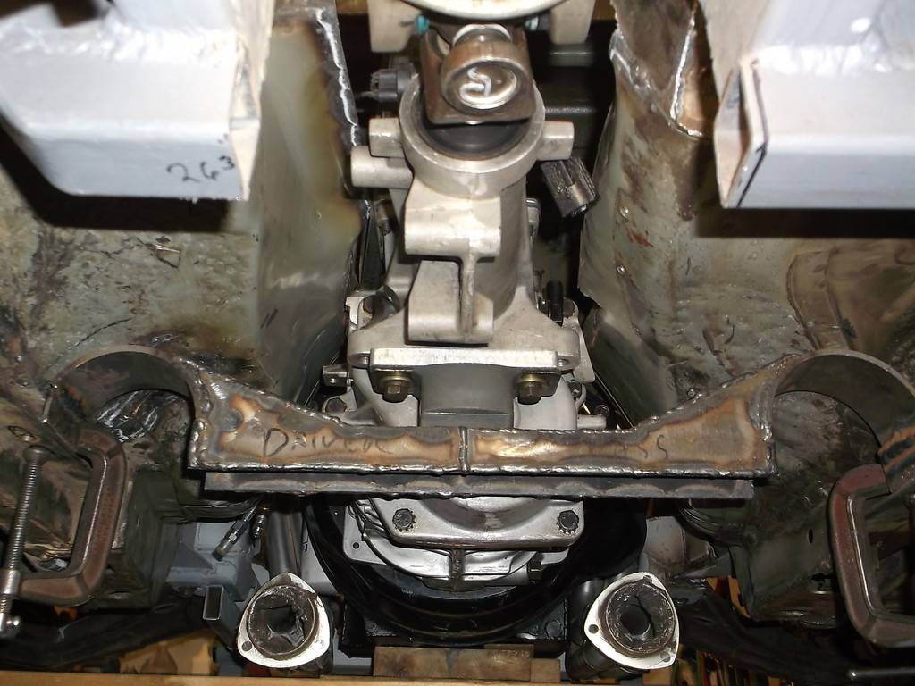
The trans xmember is made up of several pieces of 1/8 sheet steel and has a lot of weld seams and looks pretty clunky. I am going to grind all the welds smooth and after a coat of paint it should look a little more respectable.
The headers are still too low so I will have to shorten them about 2". They are made for the C3 vettes and I am a little surprised they hang that low. They are new but I paid very little for them so not upset about having to chop them up.
-
05-07-2016 #82
Registered User
- Join Date
- Jun 2015
- Location
- kent,ohio
- Posts
- 128
I got the trans and engine mounts fixed up. I raised the engine about 1 1/2" and the trans 1"
I am going to gusset the frame side of the engine mounts just for peace of mind.
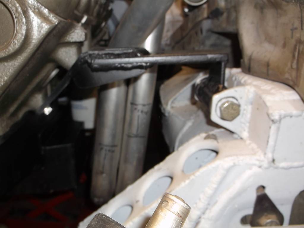
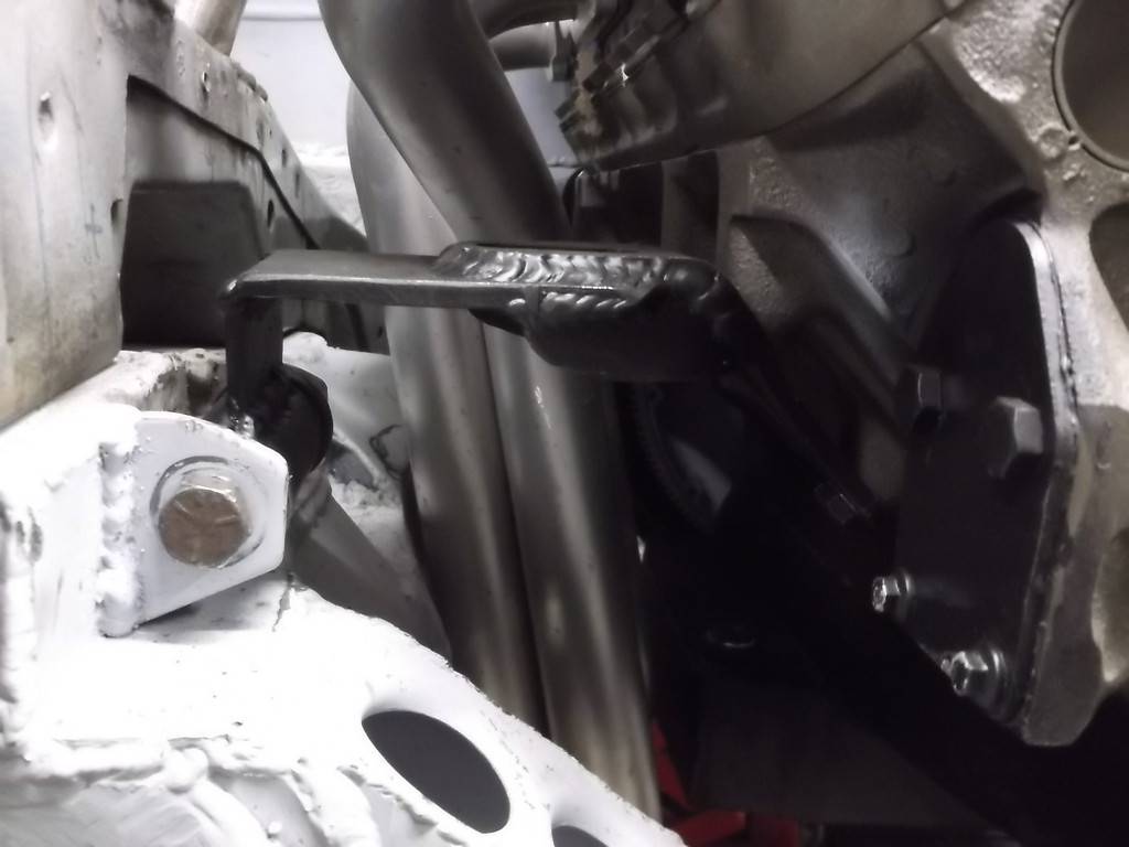
I smoothed out most of the welds on the trans mount so it desn't look so bad now.
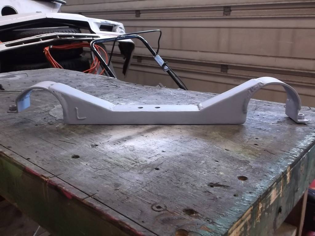
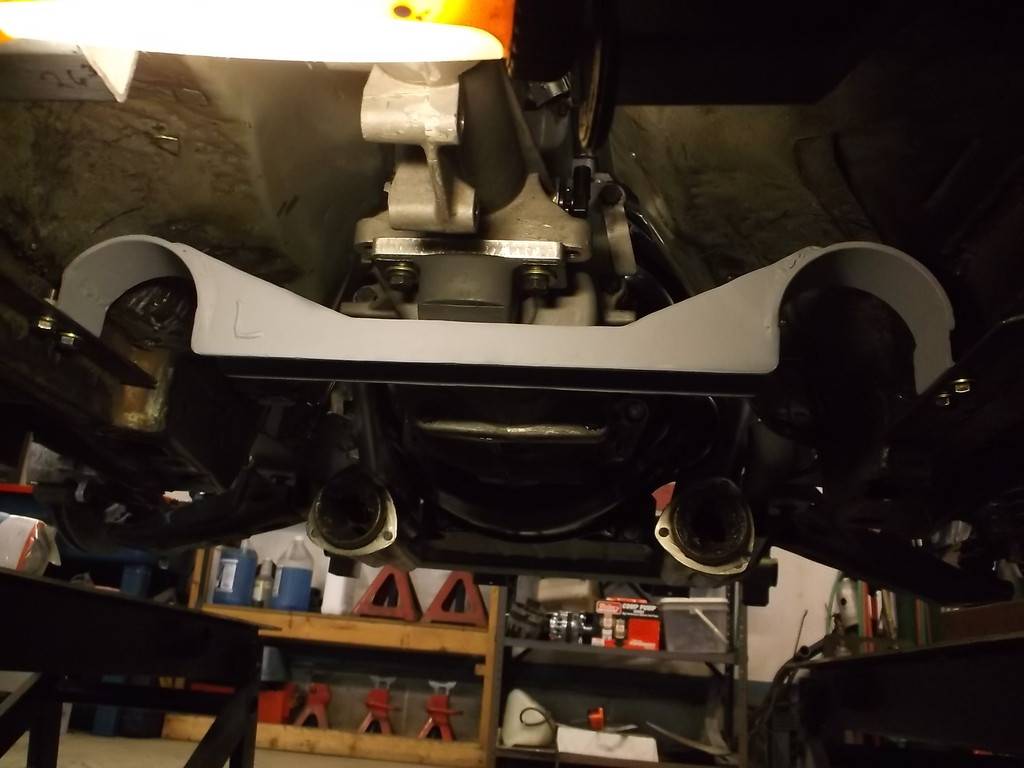
Started to mock up the new tunnel cover.
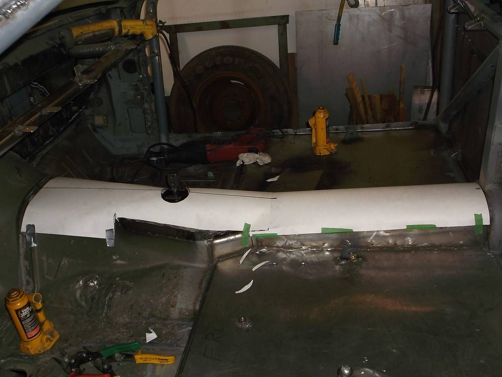
-
05-15-2016 #83
Registered User
- Join Date
- Jun 2015
- Location
- kent,ohio
- Posts
- 128
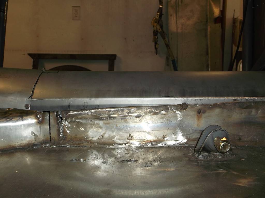
Got the tunnel pretty much ruffed in. Just some trimming and it will be ready to weld in.
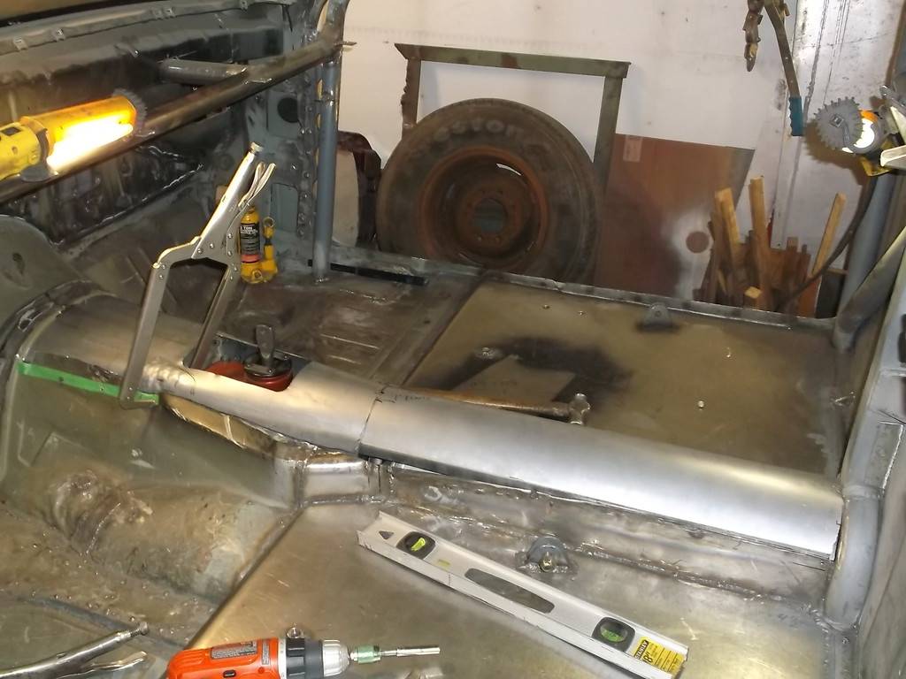
Still trying to keep the trans tunnel about stock height so had to bump out to clear the corners of the access covers.
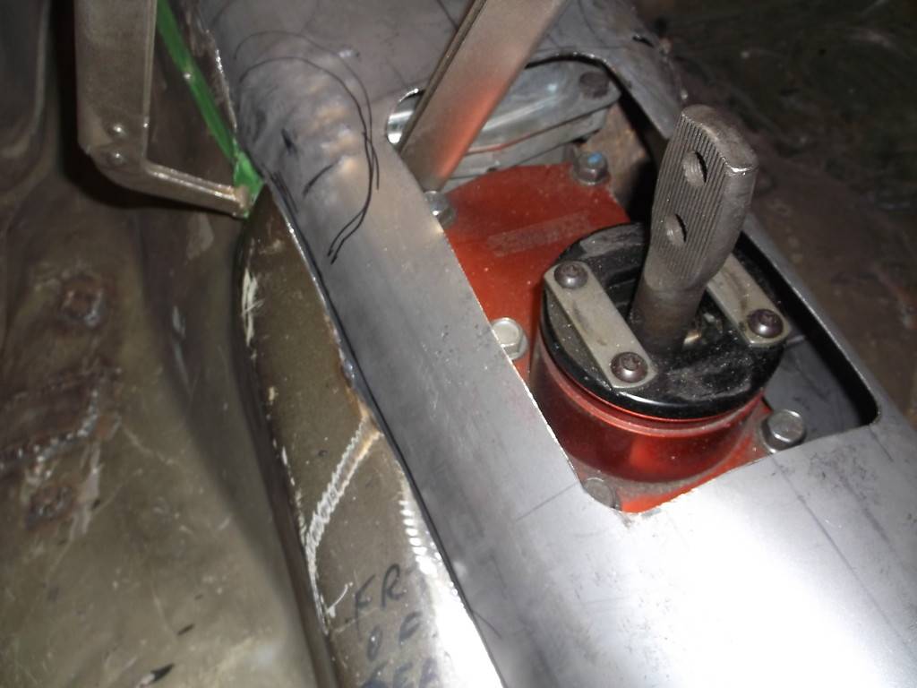
Driveshaft tunnel was raised almost 4" from previous one.
-
06-03-2016 #84
Registered User
- Join Date
- Jun 2015
- Location
- kent,ohio
- Posts
- 128
haven't got to work on the car these last few weeks. Too many outside projects now that the weather is nice. Should be back on it this weekend.
I want to thank everyone for looking in on my project. All comments are welcome, good or bad.
-
06-08-2016 #85
 Registered User
- Join Date
- Jul 2011
- Location
- Prescott, AZ
- Posts
- 206
Looks sweet! We're happy we could play a part in this build. We'd love to hear how you like the Dual-Friction once the cars up and running! Originally Posted by 83rdracer

-
06-10-2016 #86
Registered User
- Join Date
- Jun 2015
- Location
- kent,ohio
- Posts
- 128
CF, I think the clutch will work out great. In my previous life I was a commercial salesman for "The World"s Speed Shop" and literally sold hundreds of these clutches to car builders and speed shops. They have a great reputation for durability behind performance street engines and are very street friendly. I will certainly post about the cars performance when it finally hits the road and track. Originally Posted by Centerforce
-
06-11-2016 #87
 Registered User
- Join Date
- Nov 2006
- Location
- Ma.
- Posts
- 5,569
Nice work! I just went through most of your thread , tomorrow I'm going to check out the rest of it. Great job.
Wayne
Car FINALLY home !!!!!! lol
Project FNQUIK https://www.pro-touring.com/showthre...ghlight=FNQUIK
-
06-13-2016 #88
Registered User
- Join Date
- Jul 2011
- Location
- Prescott, AZ
- Posts
- 206
Great! We'll keep an eye out for that! Originally Posted by 83rdracer
-
06-15-2016 #89
Registered User
- Join Date
- Jun 2015
- Location
- kent,ohio
- Posts
- 128
Ok time for an update. reinforced the engine mounts for a little piece of mind.
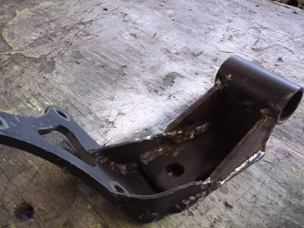
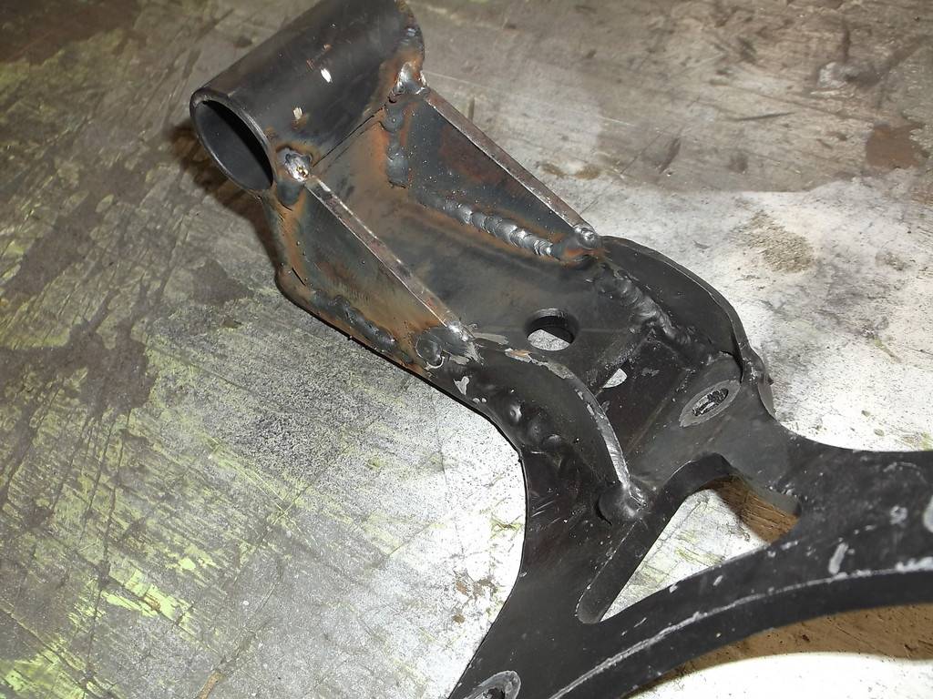
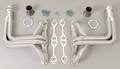
with the engine in place I decided it was time to shorten the headers. The headers are Hedman elite for a C3 Corvete. They fit in the chassis pretty well but are almost 2" too low. Since the primary pipes all come together in a tight, vertical cluster I think I can easily shorten them.
Here are the headers I have.
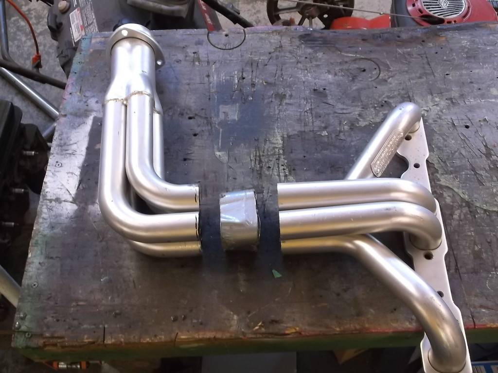
marked my cut with 2" duct tape.
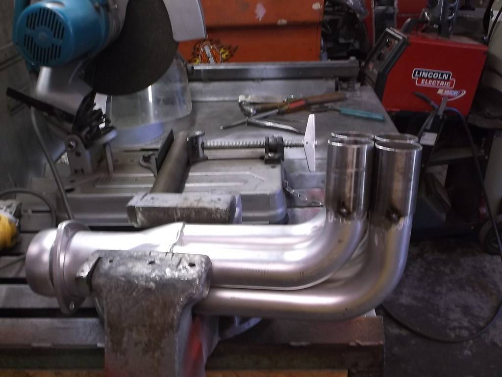
Cut tube sleeves of .060 wall 1.75od tubing, 2 3/8 long and welded to bottom half of header.
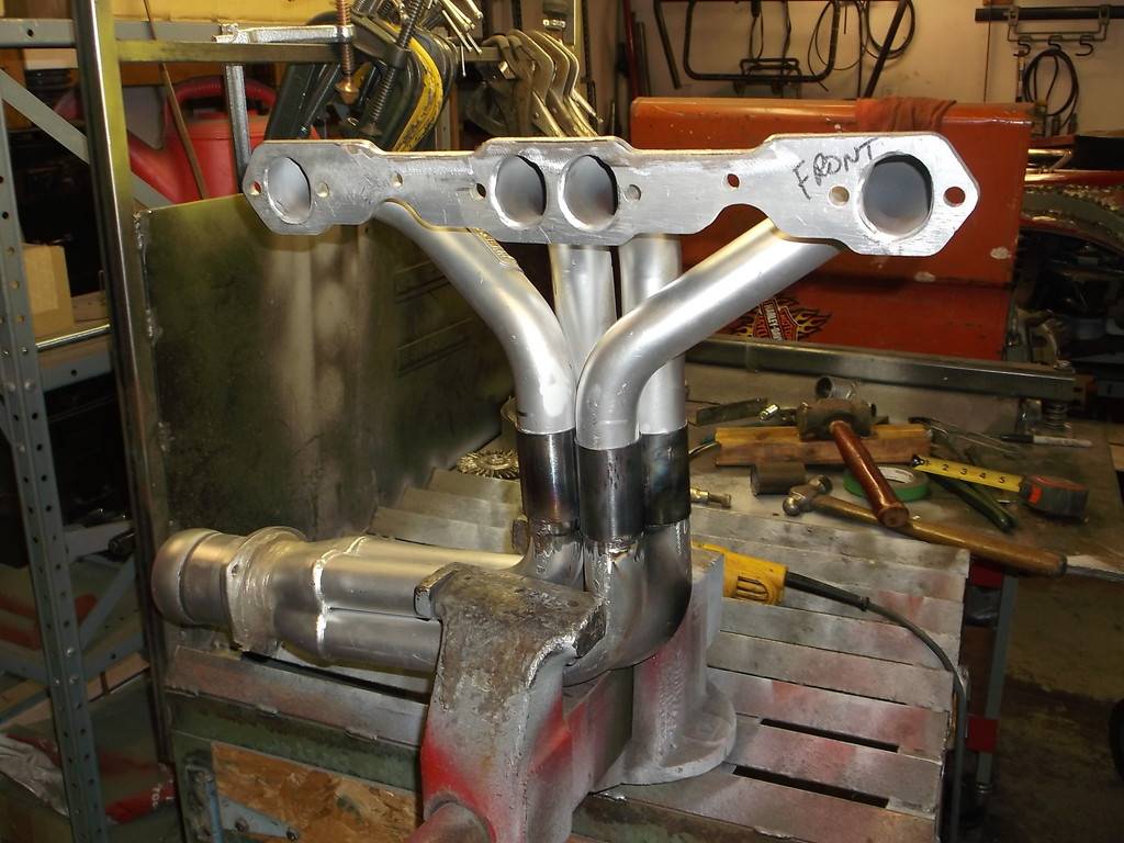
It took a little effort to get all four pipes of top half back in the receiver tubes and "persuade them down into the tubes nearly the full 2".
Once back on the car I was able to rotate the bottom half to better align the collectors to the extension pipes running along side the transmission.
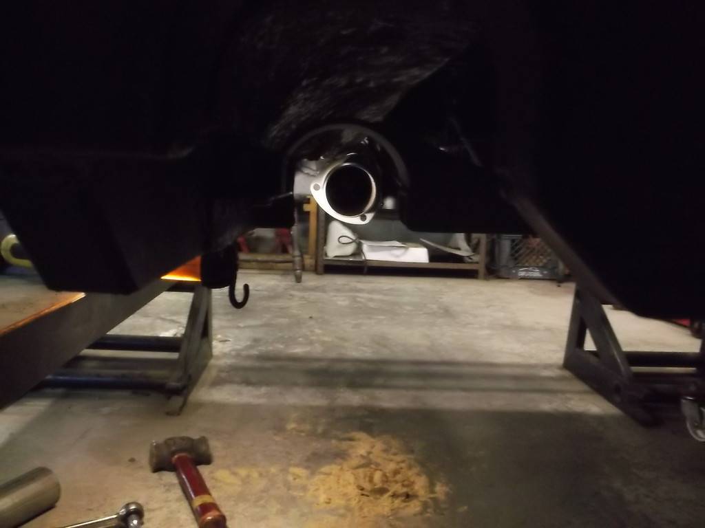
Once headers were in correct orientation I tacked the top tubes and pulled them back out to completely weld.
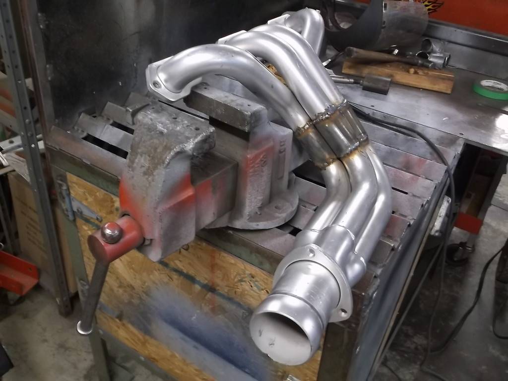
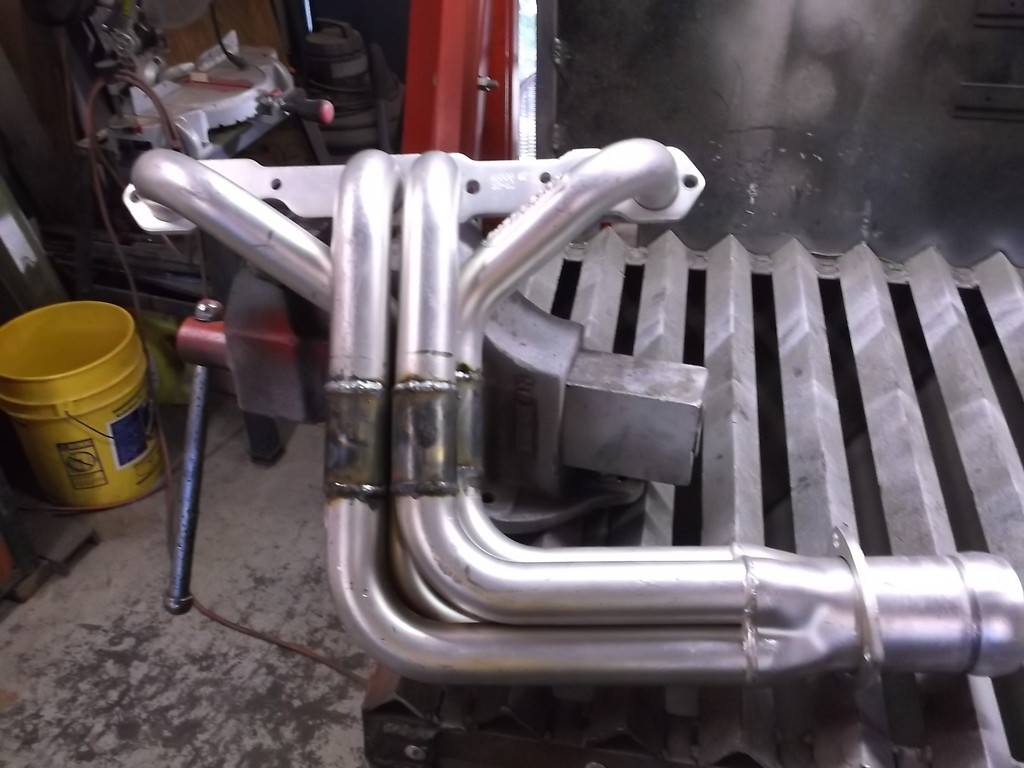
Both headers installed. Vertical height of headers is now just 16" from top of flange to lowest tube. They actually sit higher than the 7" deep road race oil pan.
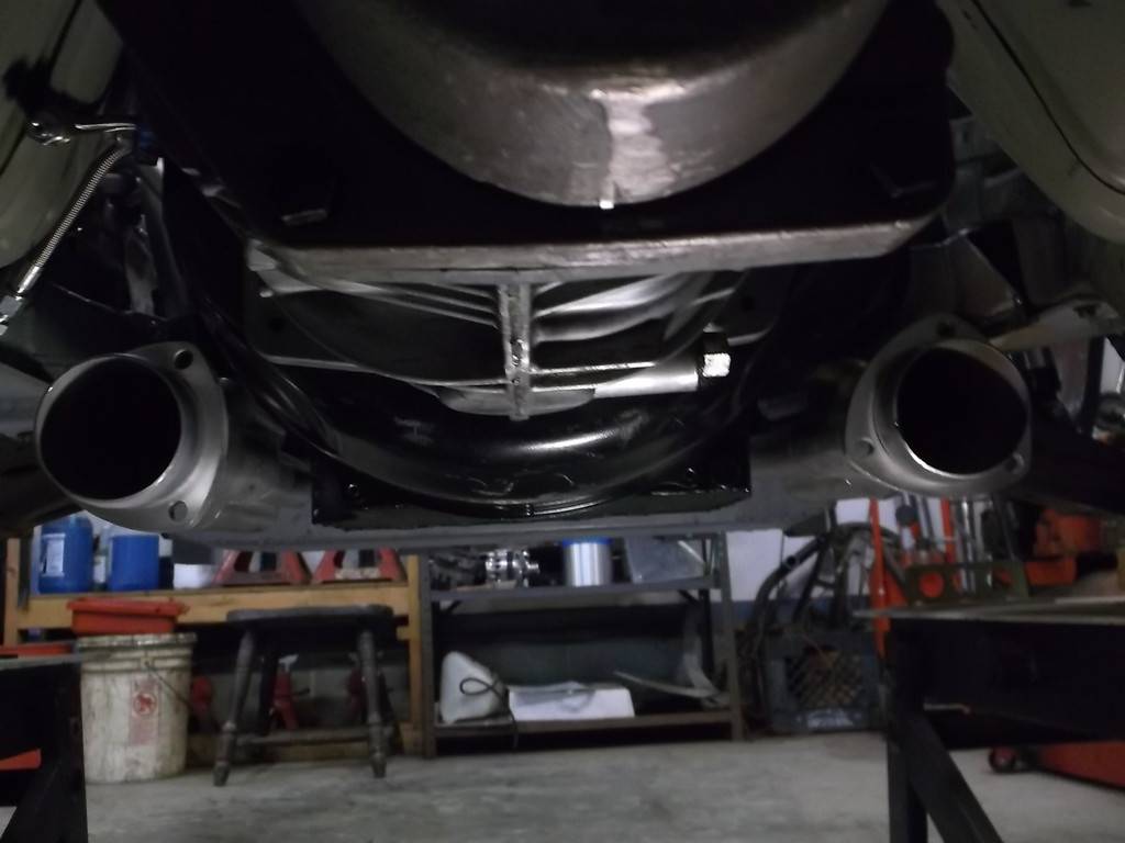
Wasn't sure how this was going to turn out but very happy with results.
-
06-15-2016 #90
Registered User
- Join Date
- Jun 2015
- Location
- kent,ohio
- Posts
- 128
With the headers in place I went about making up the exhaust. My original plan was to run a 2.5" true dual exhaust with an H-pipe. Because my engine dyno'd at 455hp and can make 500+ with a cam change I decided to step up the exhaust a little. I made 3" header extensions, 24" long, that incorporate the H-pipe.
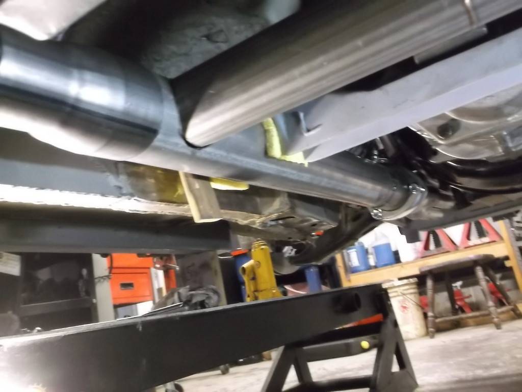
In the picture above you can see a 3" to 2.5" reducer just after the H-pipe. This allows me to connect to the 2.5" Magnaflow mufflers and side exit tail pipes that I had already fitted under the car.
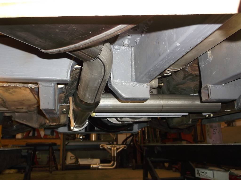
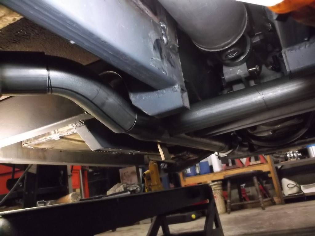

The exhaust routing was planned at the very onset of this build. 3rd gens are notorious for lack room to run any type of true dual exhaust, especially with long tube headers. I cut out and widened the subframe along side the transmission and made a double hump trans x-member. I designed the rear suspension around the side exit exhaust and raised the floor pans 5" so that I could tuck a 4" thick muffler under the car and it wouldn't drag on the ground. All of the exhaust from the headers to the tail pipes sit higher up than the SFC's and the OE subframe. The biggest reason for all of this work was so that the car could sit low,(5" nominal ground clearance at sfc's) and have sufficient compression travel (about 2.5" before bump stop), without having the exhaust or anything else under the car bottom out.
Was it worth all this effort??? Only time will tell. I am expecting exceptional performance from this car once the suspension is sorted out and it is fitted with better tires and brakes. It will certainly exceed my mediocre driving skills but in the hands of a much more experienced driver it should be a real track beast.
I have a few odds and ends to take care of mechanically and then the plumbing and electrical work will start. After more than 5 1/2 years I can't wait to fire it up and drive it out of the garage. Please keep watching and commenting as it helps keep me motivated to finish this thing.
Dave
-
06-15-2016 #91
Registered User
- Join Date
- Jun 2015
- Location
- kent,ohio
- Posts
- 128
Wayne, thanks for looking in.The entire build is on the Thirdgen.org website in the Fabrication forum under "Homebrew road racer". Hopefully I am on the downhill side of this project with wiring and plumbing left before it fires up. Originally Posted by Motown 454
-
06-15-2016 #92
Registered User
- Join Date
- Jun 2015
- Location
- kent,ohio
- Posts
- 128
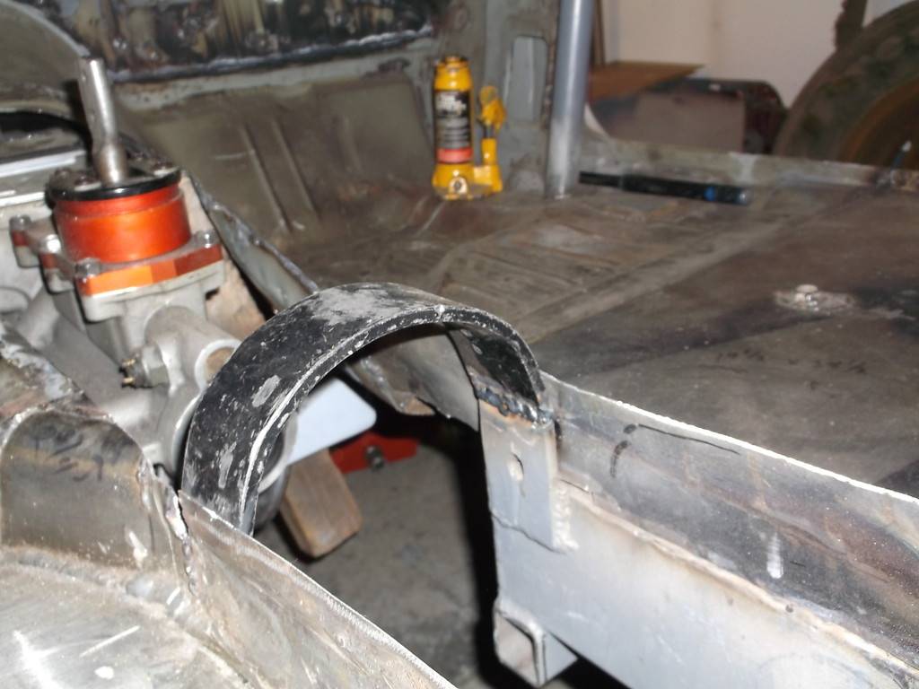
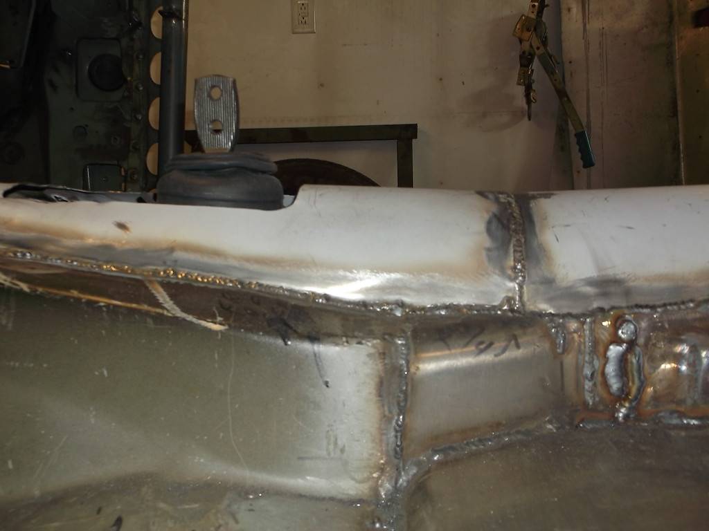
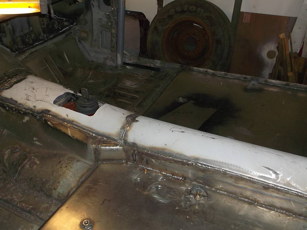
quick pics of the tunnel all welded up.
New upper driveshaft loop.
-
06-21-2016 #93
Registered User
- Join Date
- Jun 2015
- Location
- kent,ohio
- Posts
- 128
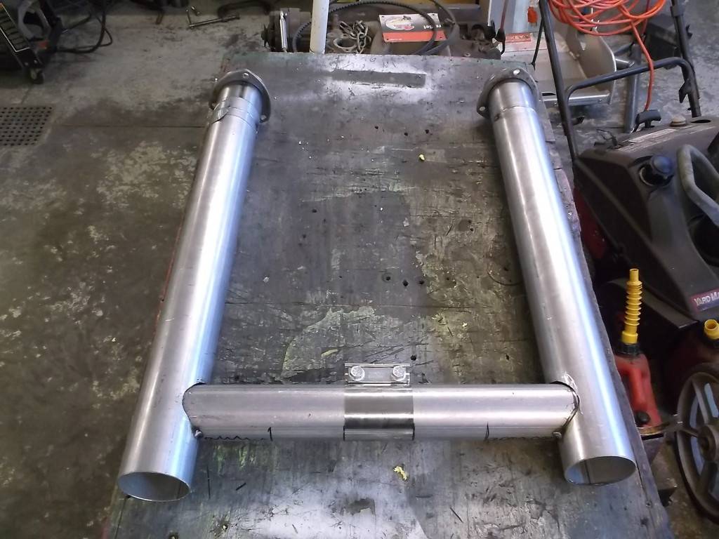
A little more work on the H-pipe.
H-pipe tack in place. I cut it into two pieces so it can be taken out as one piece or one side at a time.
I added a wire hanger to each side of the H-pipe.
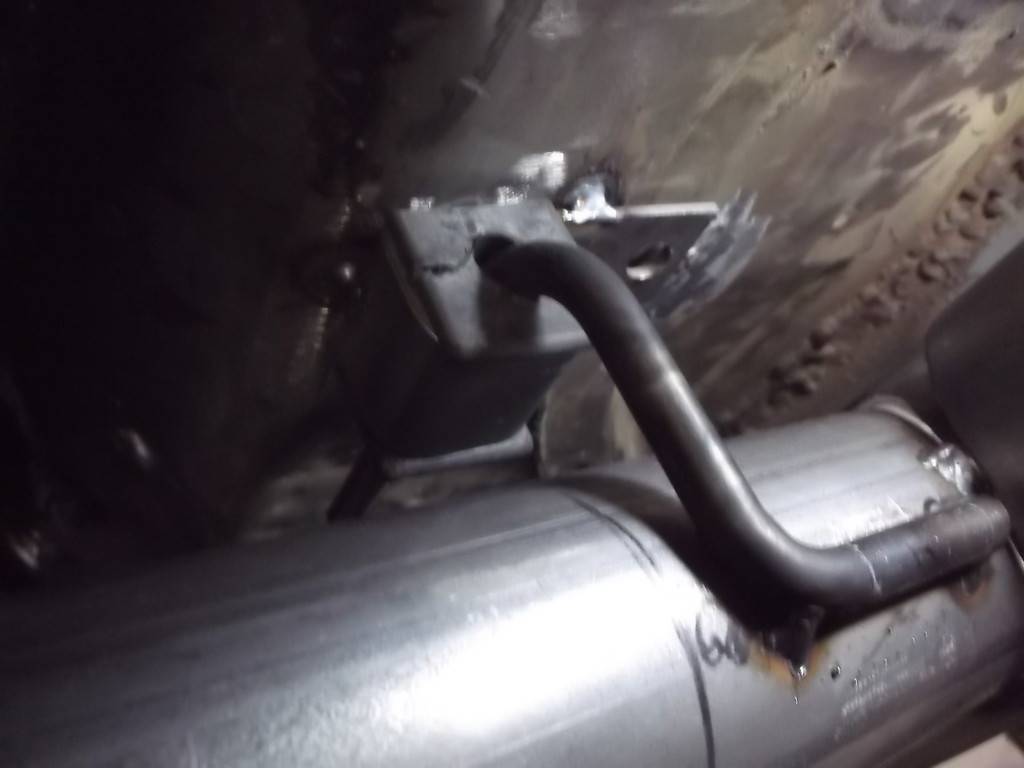
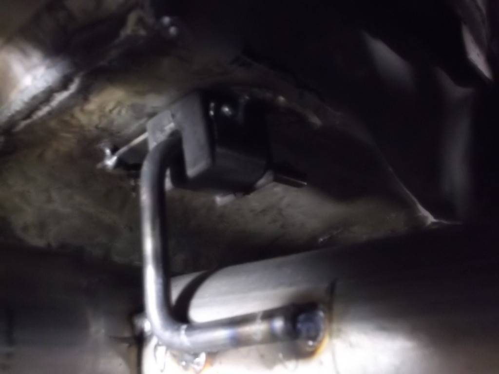
H-pipe suspended from hangers. Fits great!!!!
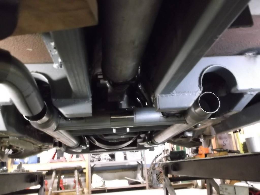
-
07-24-2016 #94
Registered User
- Join Date
- Jun 2015
- Location
- kent,ohio
- Posts
- 128
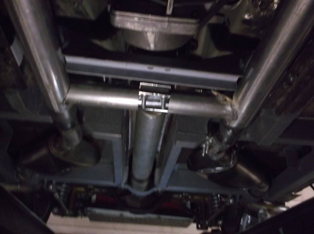
Haven't posted for a while so time for an update. Exhaust is nearly finished, just a couple pipes to finish welding up and a couple hanger brackets to weld to floor pan. I can't believe how "clean" the bottom of the car turned out, even though that was a goal of mine. The exhaust is tucked up very nicely. The picks are a little dark and don't do it justice.
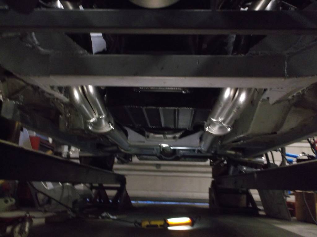
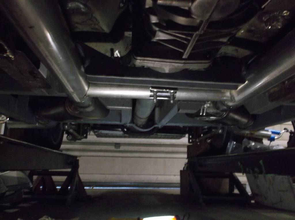
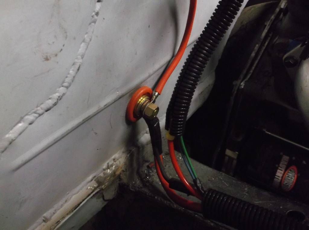
Ive been working on the engine compartment wiring. Pretty simple, ignition and starter, electric fan and controller and sensors, and lighting. To keep cost down I am using as much of the stock wiring as I can, removing unused circuits and adding what I need. battery will be mounted behind front passenger seat, Main battery cable will run to a master cutoff switch mounted in center of dash above shifter. From there it will go to a bulkhead connector in the firewall located just above the right frame rail. I am using a remote "hot start" solenoid mounted at the front of the right strut tube. Main cable runs from firewall bulkhead connector to start solenoid and from solenoid to starter. Routing starter cable from front of car back to starter makes it easier to route cable away from header.
Firewall feed through.
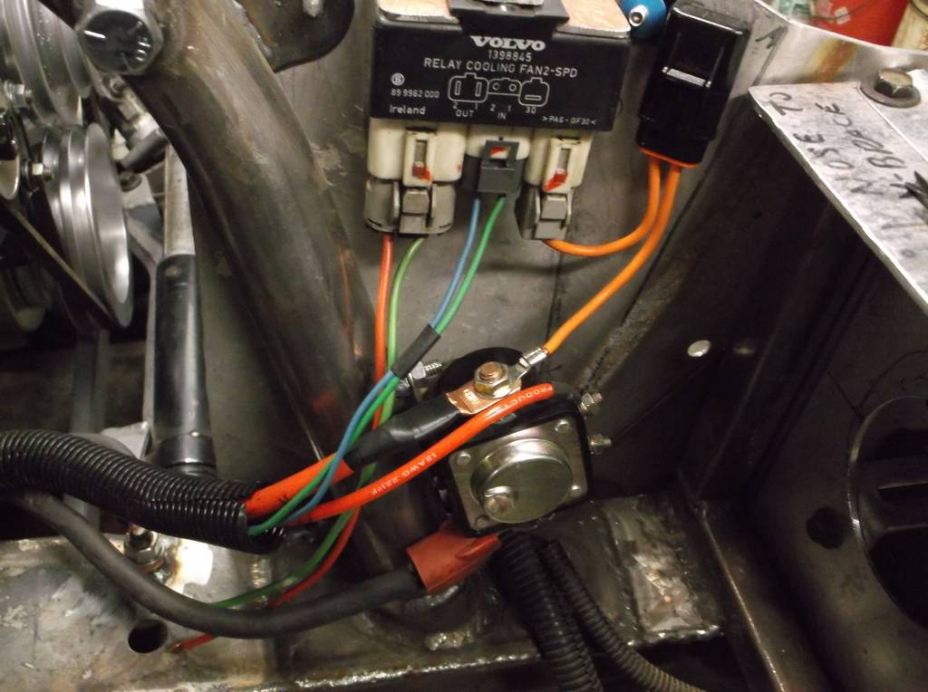
Hot start solenoid.
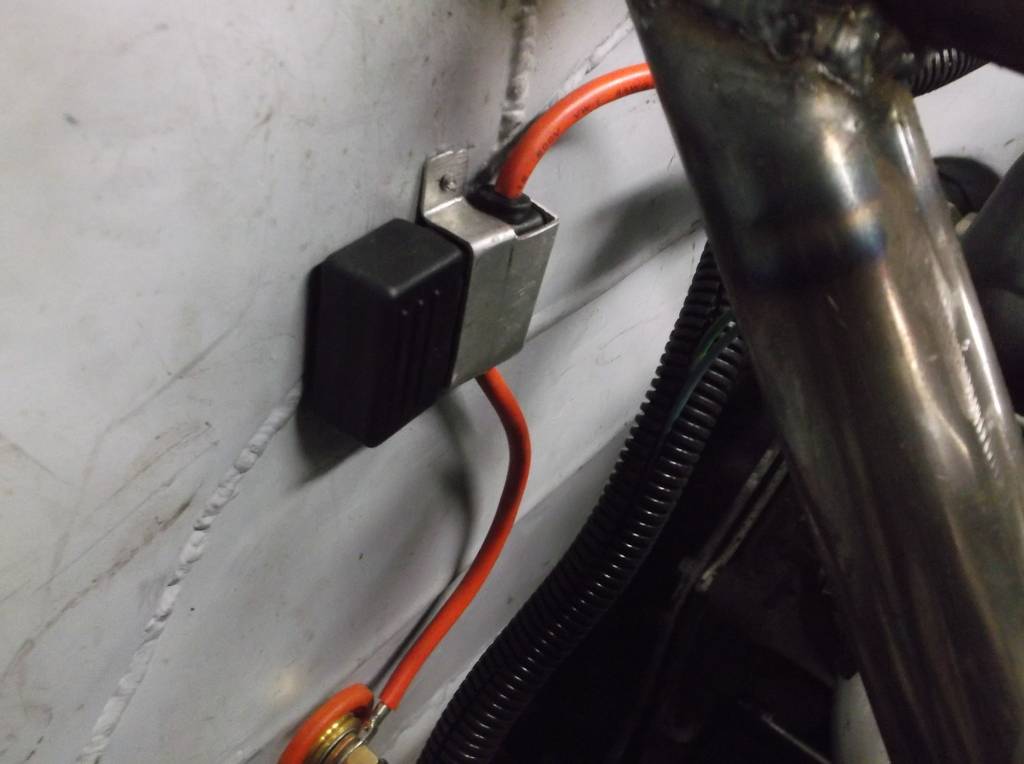
Factory wiring used battery lug on starter for power source back to ignition switch and headlight switch and was protected with 2 fusible links. I cut out the fusible links, shortened the wires and added a 40 amp Maxi fuse inline to bulkhead connector.
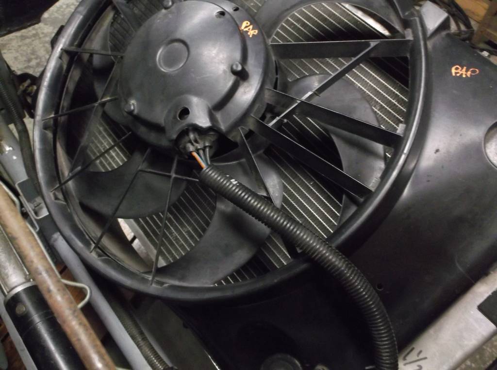
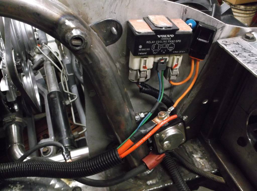
I remounted the 2 speed electric fan from the '99 Grand Marquis and wired it into the Volvo fan controller. The controller uses modular weatherpack connectors that I was able to disassemble, remove the volvo lead wires and crimp/solder in my own wiring and avoiding a bunch of splice connections.
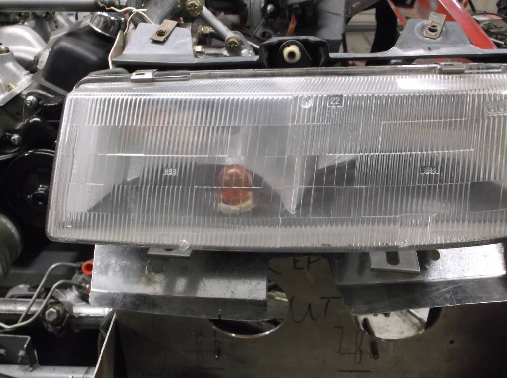
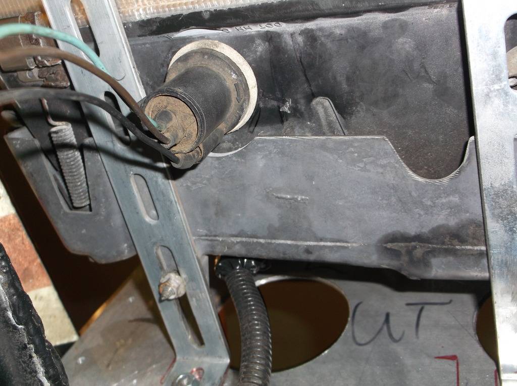
I am using headlight assemblies from a '90-93 GM APV mini van. They use 9005 and 9006 bulbs so I had to disassemble those weatherpack plugs and solder in the wiring from the Camaro. Like most newer GM trucks the low beam turns off when the high beam is used. I could correct this with some relays but I think I will run the low beams as daytime running lights and activate the high beams with the stock dimmer switch. Another problem I had was where to relocate the front turn/parking lights. The light assemblies on this car were broken and I also wanted to use the openings in the front valance for brake ducts. After going over several different ideas I decided to move the factory light sockets to inside the APV headlight assemblies. I had room for the socket and bulb to be inserted from the bottom just left of center and towards the front of the housing. This should make the turn signal very visible even with the low beam on and hopefully won't create a shadow when the hi beam is on.
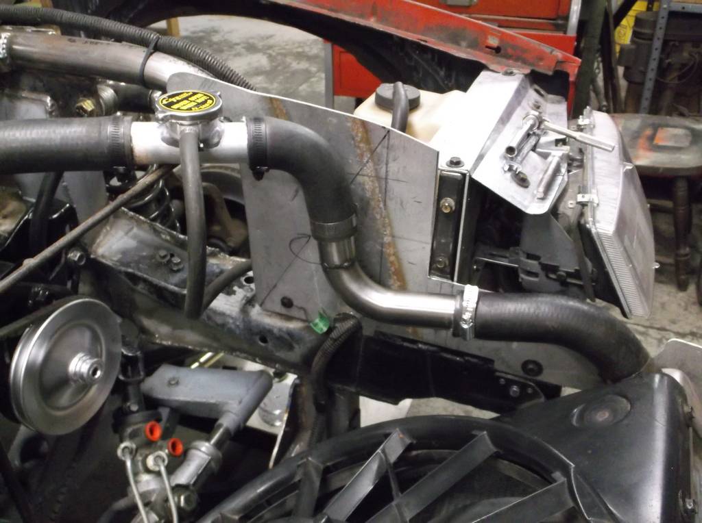
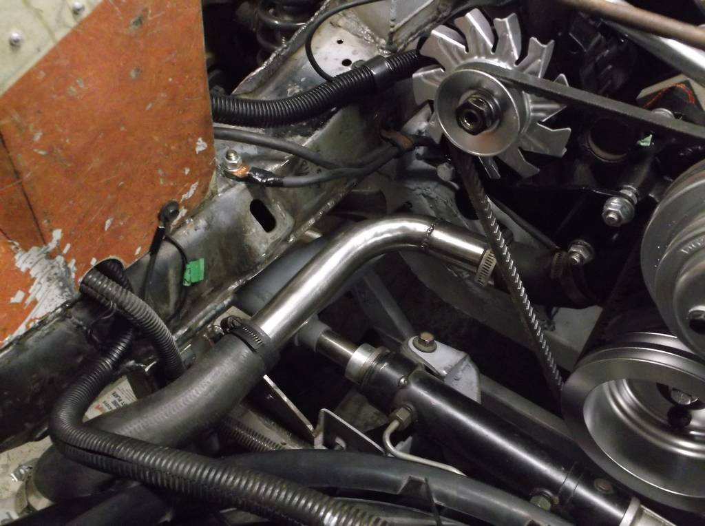
Finalized the radiator hose routing. Still beed to make brackets to secure hose locations.
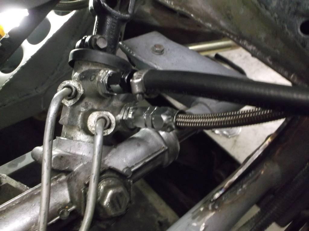
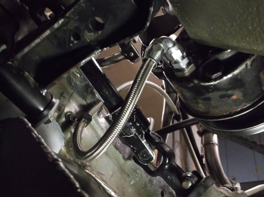
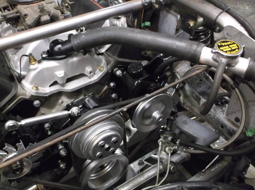
Plumbed the p/s pump to the 4th gen rack and pinion. Because th 3rd gen Camaro pump was for a gear box and not a rack I had to reduce the pressure output. I found a shim kit from Borgenson that allows adjustment from 1300psi down to 750psi. I shimmed mine for 850psi and can easily change it if I need more or less pressure to get the correct "feel". I made my own lines. The pressure line is made from teflon lined, steel braided hose and STEEL fittings. Also need to get metric o-ring to -6AN adapters for the rack and pump. Return line is low pressure hydraulic hose rated to 350psi and pushes over barb fittings and secured with hose clamps,
-
08-01-2016 #95
Registered User
- Join Date
- Jun 2015
- Location
- kent,ohio
- Posts
- 128
The exhaust is finally finished. All pipes are welded and all the hangers are in place. This took a lot more time than I thought it would. getting the hangers in a position to hold the exhaust in place and still allow easy install and removal was a lot of trial and error (mostly error).
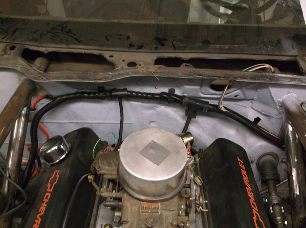
More work on the wiring. The front of the car should be done. I got all the lights working and the turn signals are very visible with the low beams on and do not seem to cause a shadow when the high beams are on.
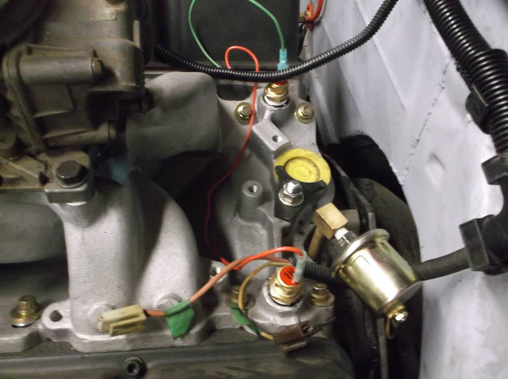
The fan sensors arrived and those are wired in. I am running a 180* thermostat and the low speed fan is set to come on at 195* and the high speed fan at 210*. The temp warning light in the dash will flash at 235*.
Fan sensors installed in water ports at rear if intake manifold. Oil pressure sensor wired in as well.
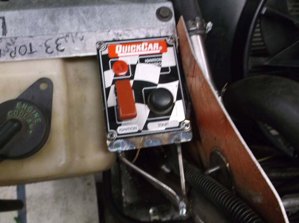
I added a remote start switch panel to the left headlight support. This will allow me to bump the engine over or start it from outside the car. The location makes it easy to see the timing marks, reach #1 spark plug or work the throttle. This will make it easier to tune the car at home or make adjustments at the track.
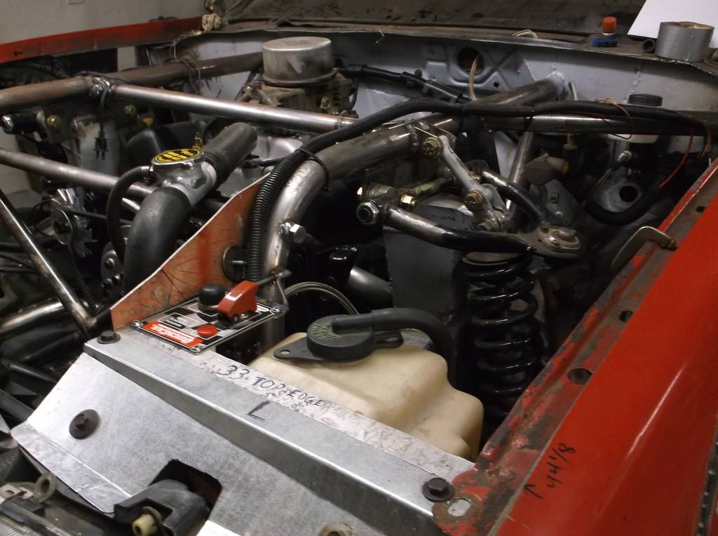
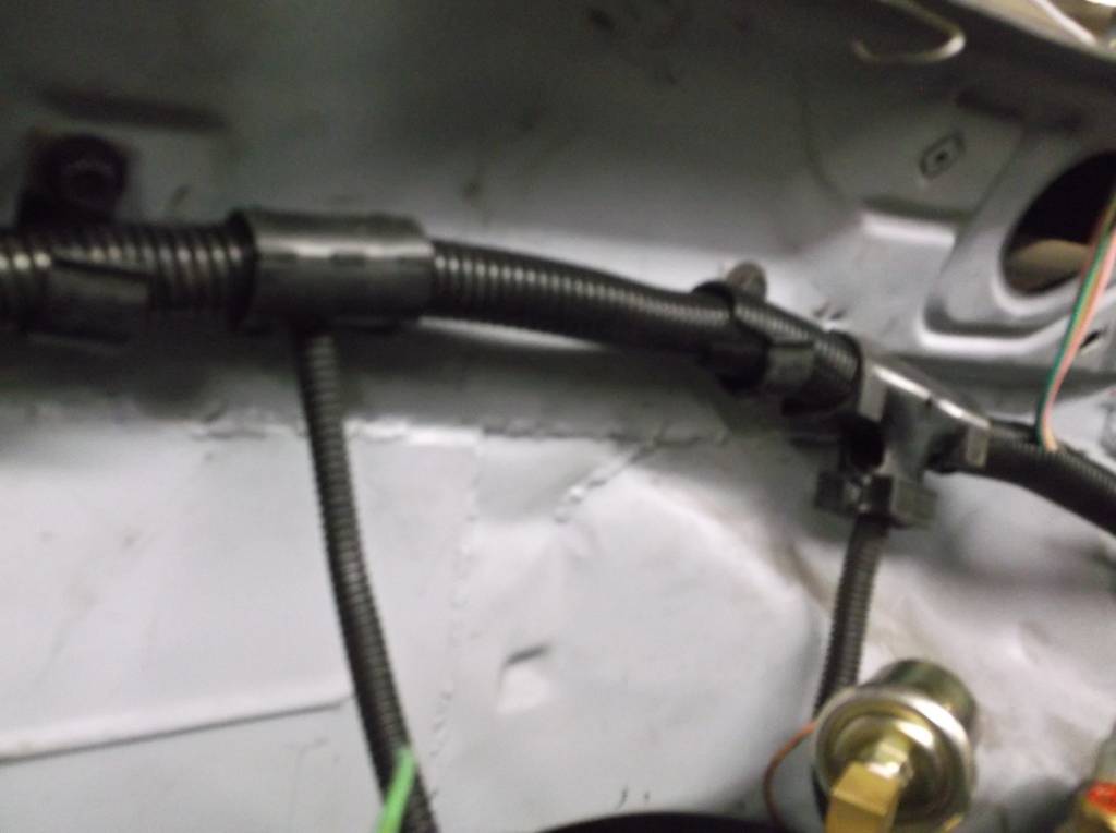
Since I saved all the factory wiring from the Camaro and my old C1500 I have plenty of the convoluted tubing, connectors and tees to encase the wiring. This made keeping the wiring neat and tidy, easy and cheap.
-
08-01-2016 #96
 -Moderator/Sponsor-
- Join Date
- Apr 2001
- Location
- The City of Fountains
- Posts
- 16,120
I hope that's a quality MaxiFuse holder. I just went through a bunch of BS with my Cougar because I used a crappy one.
Andrew1970 GTO Version 3.0
1967 Cougar build
GM High-Tech Performance feature
My YouTube Channel Please Subscribe!
Instagram @dr__efi
I deliver what EFI promises.
Remote Holley EFI tuning.
Please get in touch if I can be of service.
"You were the gun, your voice was the trigger, your bravery was the barrel, your eyes were the bullets." ~ Her
-
08-14-2016 #97
Registered User
- Join Date
- Jun 2015
- Location
- kent,ohio
- Posts
- 128
Andrew thanks for looking in on my build. The MaxiFuse and ATO fuse holders are both NAPA/Echlin products. I sold NAPA parts for 13 years and the Echlin electrical parts were always of very good quality so not too concerned. I have tried to minimize resistance and voltage drop by soldering most of the connections and minimizing the number of splices. I have even taken the spade connectors out of the factory plug connectors removed the factory wiring from the connectors and soldered in my wiring to eliminate splices. Originally Posted by andrewb70
I did purchase a pair of 30 amp 5-pin relays from Summit Racing sold by the VIAIR corporation. VIAIR sells 12 volt air compressors for the off-road crowd and emergency crews. I thought their relay kits would be of better quality due to the harsh conditions there products are made for. I always due a "tug" test on any crimp or soldered connection and when checking the wire leads coming from the relay sockets I had 3 of them pull out of the spade connector they were crimped to. Two of them actually pulled loose from the crimp and on the third the crimp actually cut through the wire strands and was only held in place by the insulation. Needless to say I had to take all of the connectors apart and solder them for my own peace of mind.
Still working on the wiring so no new pics. Hoping to get this thing fired up in the next couple weeks!!!
-
10-12-2016 #98
Registered User
- Join Date
- Jun 2015
- Location
- kent,ohio
- Posts
- 128
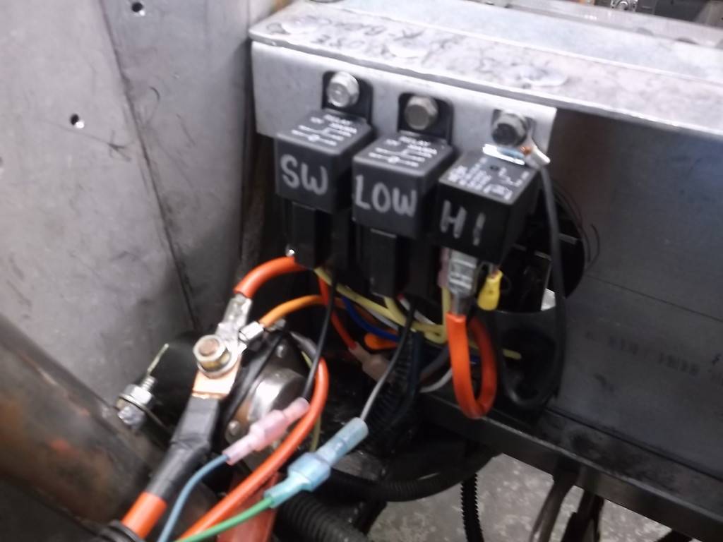
Its been a while since I last posted but I have made good progress on the car. First there was more issues with the fan, fan controller and alternator. Whenever the fan switched to the high speed side it caused my single alternator v-belt to slip, burn actually. After having the alternator checked at a reputable rebuilder's shop, was ok, I got a new belt and did so web searching on my fan. It turns out that Mercury uses a seperate 30 amp fuse and relay for low speed and a 50 amp fuse and relay for the high side. My trick, compact, Volvo fans controller was not capable of powering the high speed fan motor. I ditched the Volvo controller and replaced it with a 3 relay setup. I have a 30 amp relay and fuse to run the low speed side, a 70 amp relay and 50 amp fuse to run the high side and the third fuse is used to turn off the low side and turn on the high side.
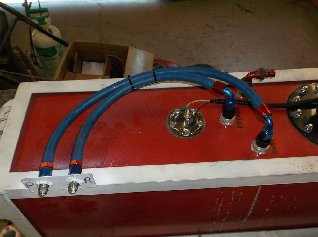
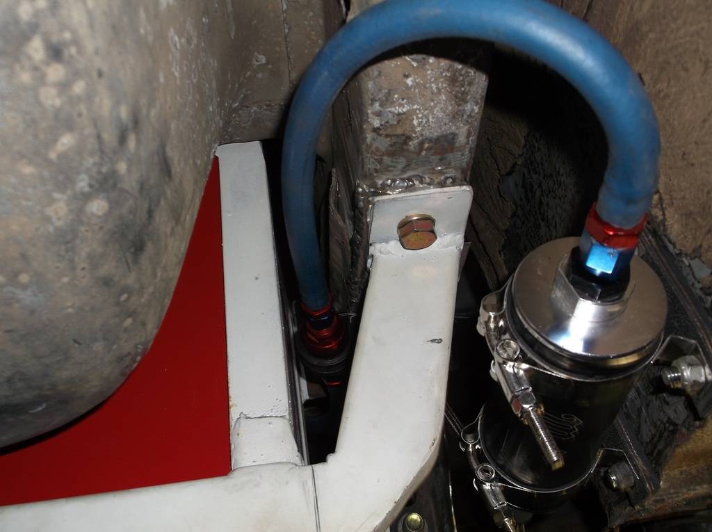
Next up I plumbed the fuel system. Because of budget constraints I used some push-lock hose at the rear to plumb from tank to fuel pump. I have a Mallory 110gph inline pump with a 40 micron prefilter. All lines are -6.
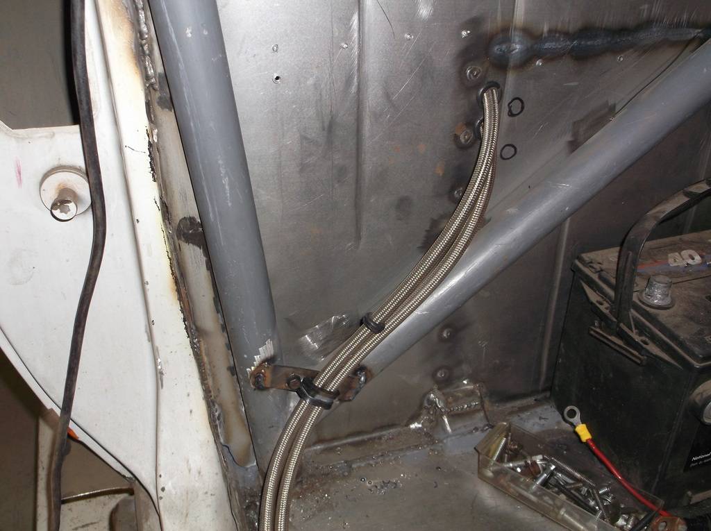
From pump to carb and the return line I ran braided ptfe hose. Because the car sits so low I had to run the fuel lines through the passenger compartment. They come in through the rear firewall behind the passenger seat and run along the floor at the door opening pinch weld. They exit into the engine compartment above the right front frame rail.
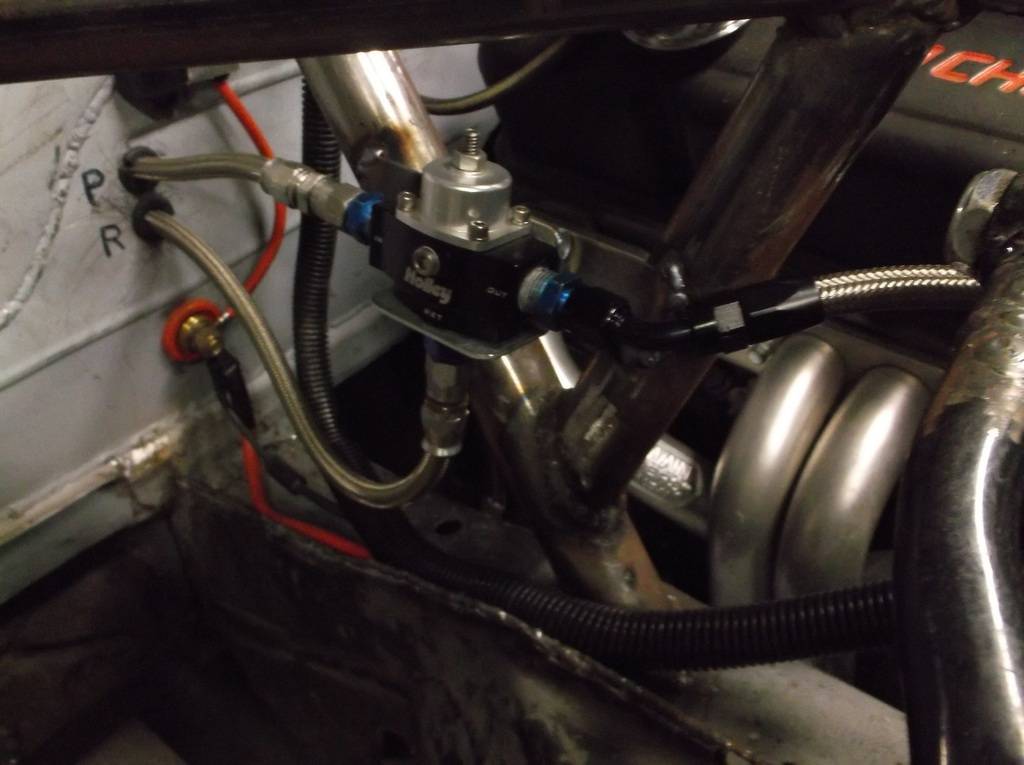
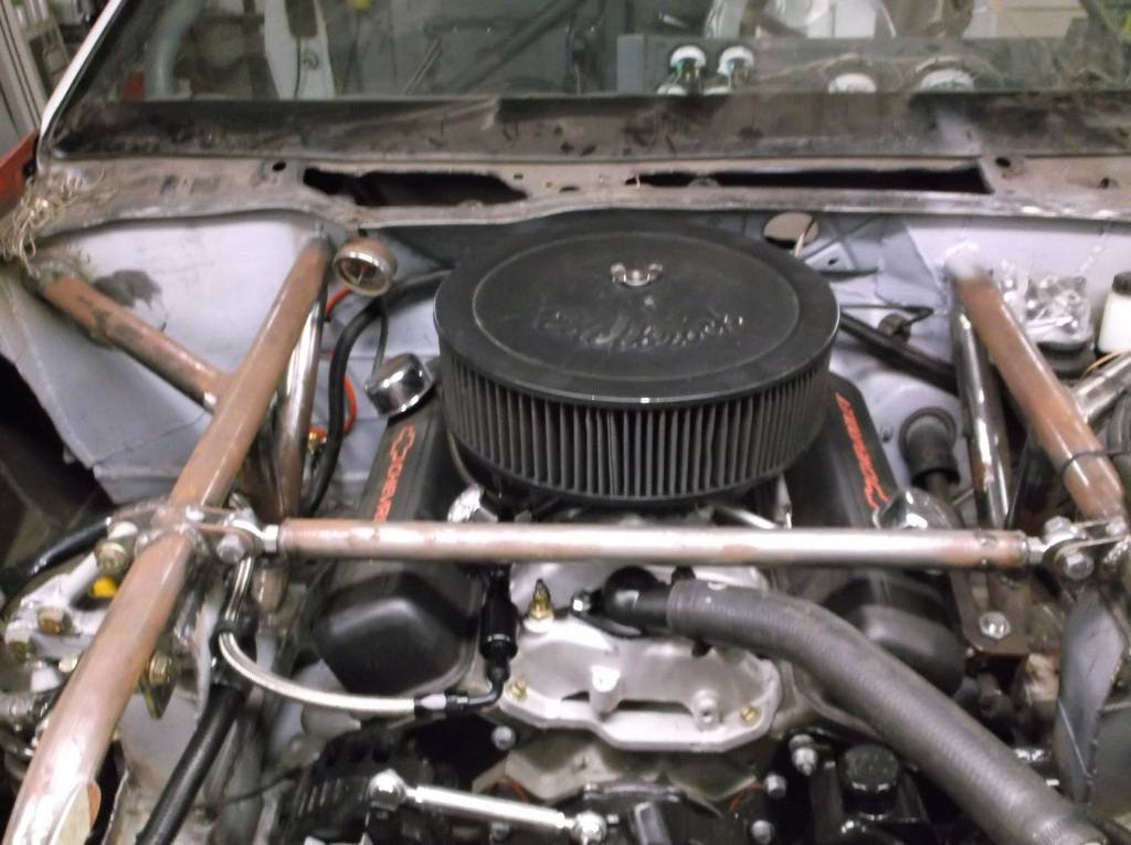
Holley billet return style regulator and another 40 micron filter before the 750cfm 4160 carb.
Plumbing the brakes was the last major mechanical system that had to be figured out. Master cylinder is a Dorman aluminum replacement unit for a mid 70's Cordoba. It has a 1.063 bore. All lines are 3/16.
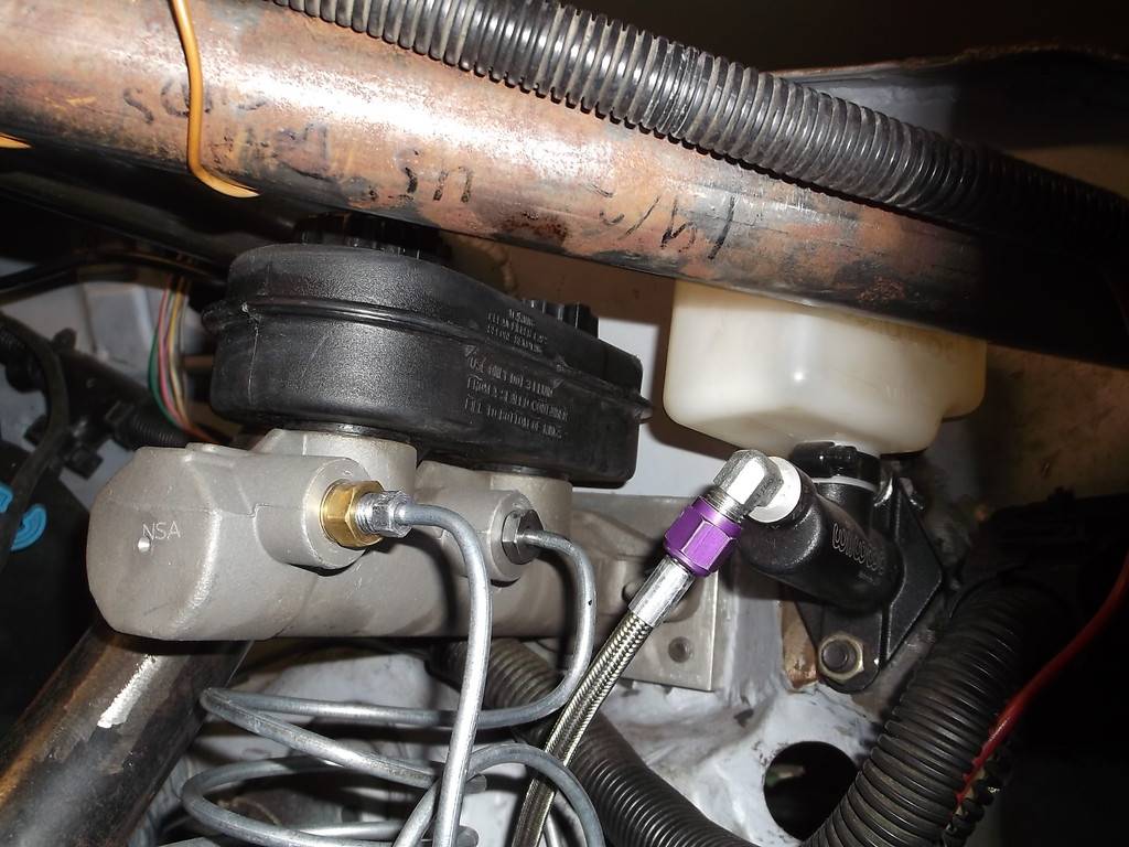
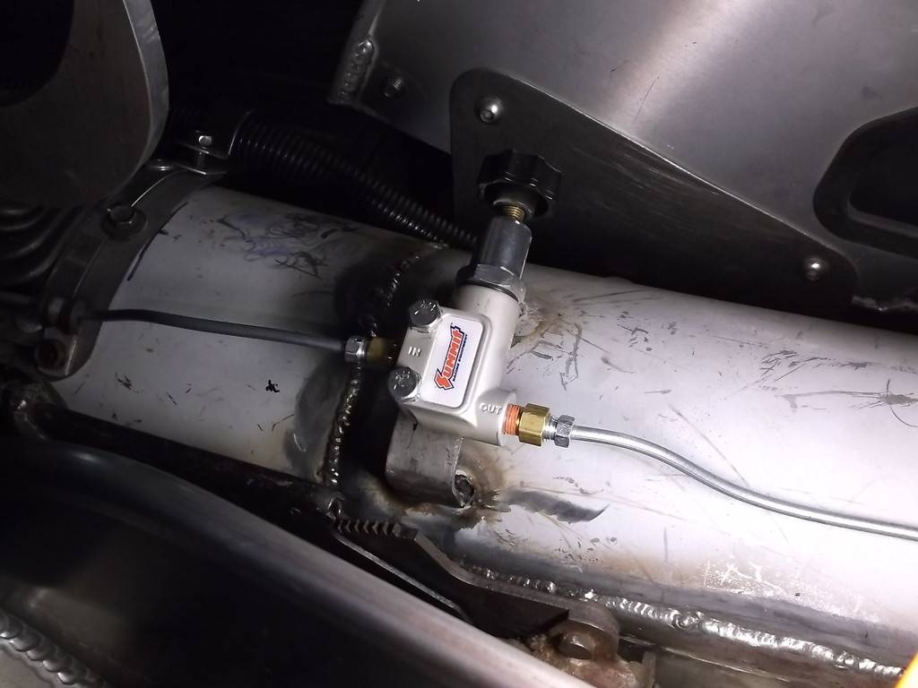
The rear brake line also runs through the interior along the top of the tunnel. I spliced in a Summit adjustable proportioning valve between the seats. With the valve mounted here I can fine tune the rear brake bias for street or track.
I still need to make up some e-brake cables but I have the winter to work those out.
-
10-12-2016 #99
Registered User
- Join Date
- Jun 2015
- Location
- kent,ohio
- Posts
- 128
Now the car should start, stop and steer, so its finally time to get it out of the garage after nearly 6 full years.
1st get it off the ramps. Slide the lift bar into the rear of both ramps and raise them up to clear the triangle stands.
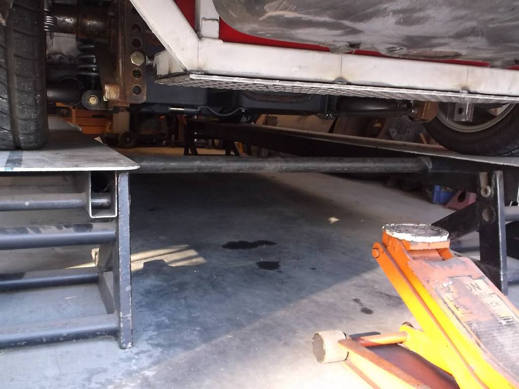
lower the ramps to the ground, remove the jack and slide in the ramp extensions
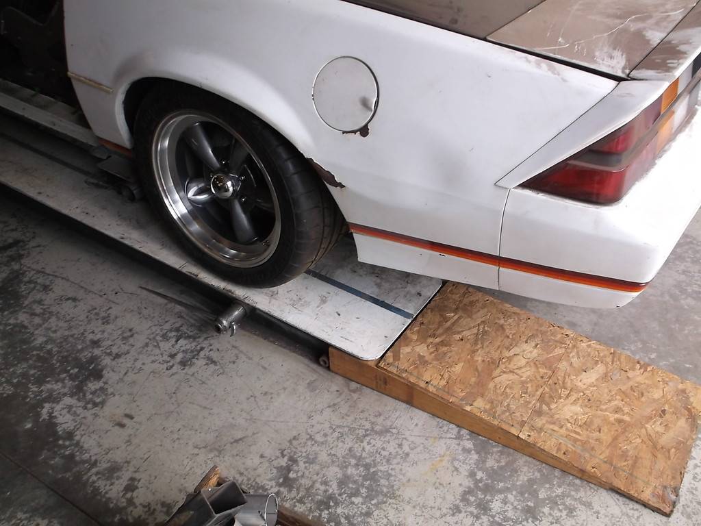
The ramps are only at an angle of 4.5 degrees so even cars with low ground clearance and long overhangs can get on and off without scraping.
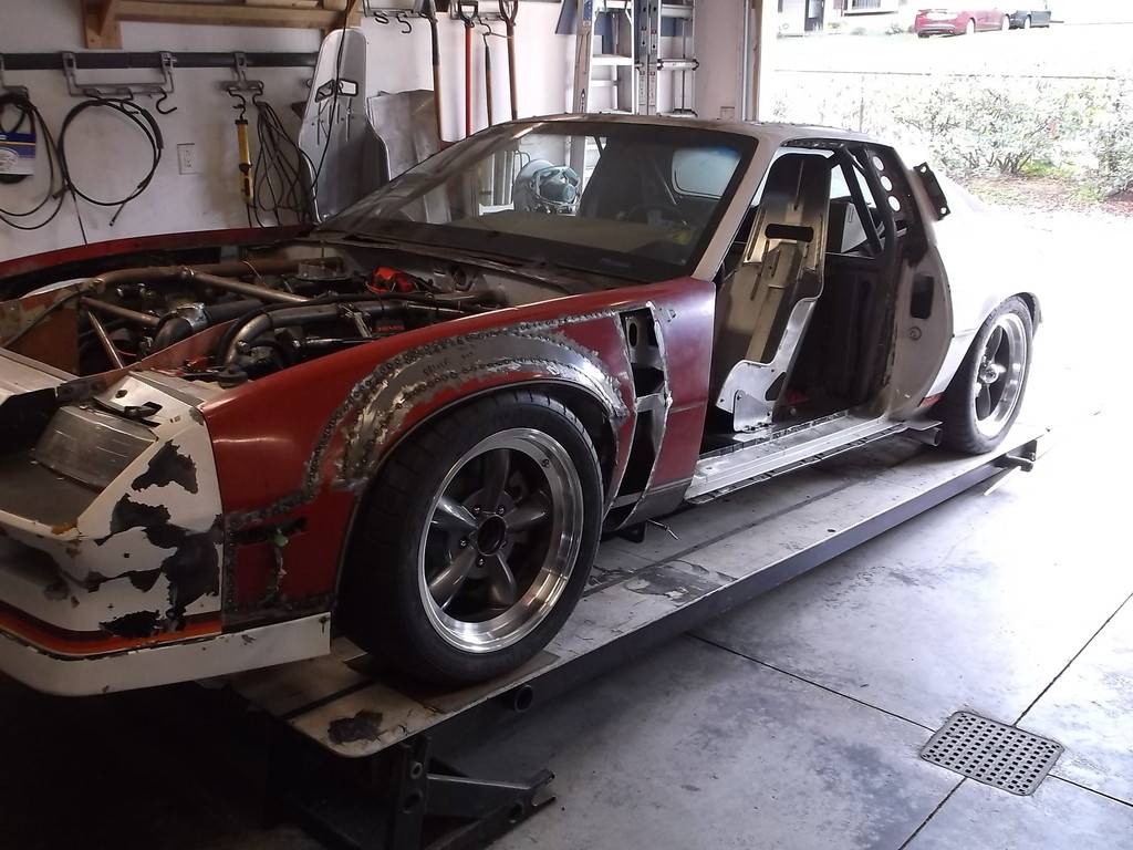
I coasted the car down the ramps and out of the garage. I fired up the engine and let it come up to temperature. Finally the moment of truth as I pushed in the clutch, slipped the TKO600 into reverse and with a little gas and clutch backed the car up. IT MOVES UNDER ITS OWN POWER!!!!!! The exit out of the garage is tight, requiring some back and forth to get out onto the concrete driveway. All the turning and stop and go helped settle the suspension. Ground clearance on the ramps was 5"F/6"R but now was 3 3/4F and4 1/4R.
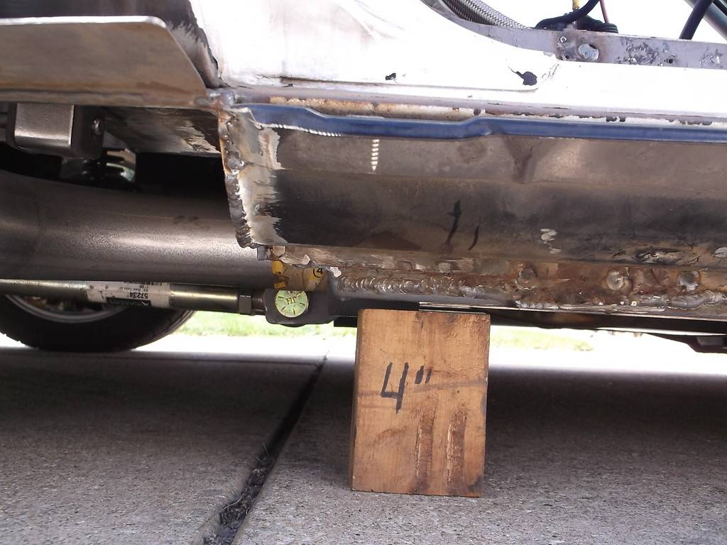
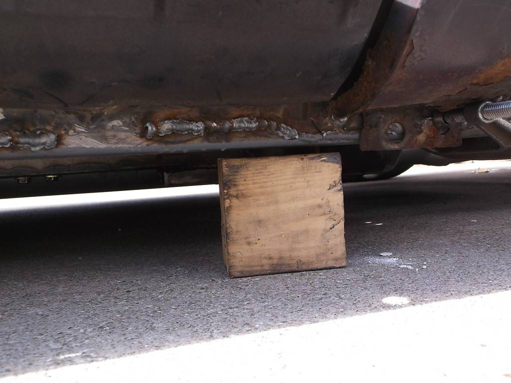
Thats really low but it looks cool sitting down on the tires a little.
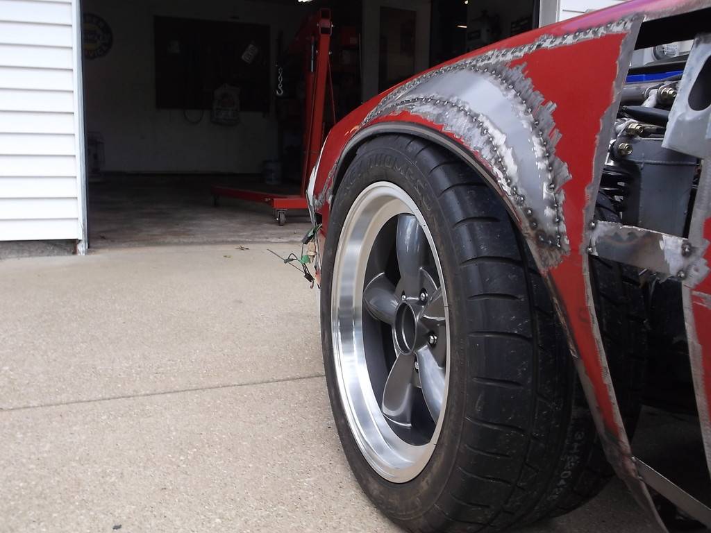
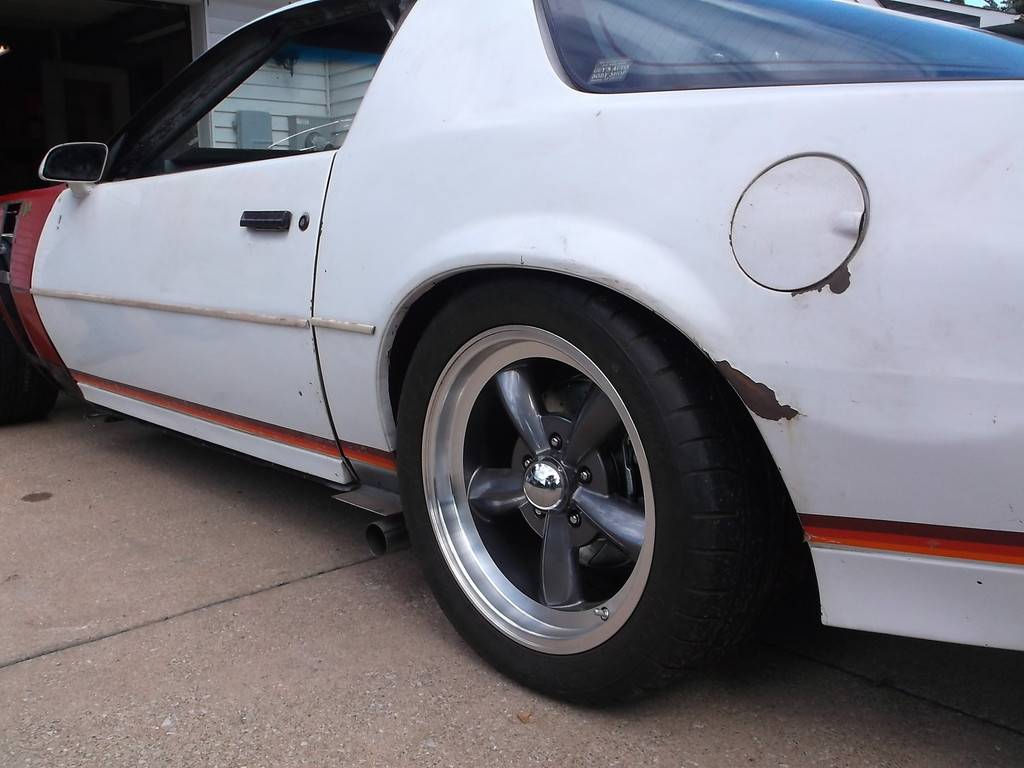
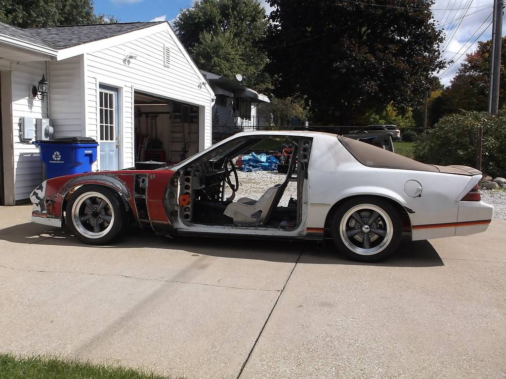
I had some friends come over and help put the doors on. They weigh about 95lbs each so we used the engine hoist to lift them up. Now its starting to look like a car again!
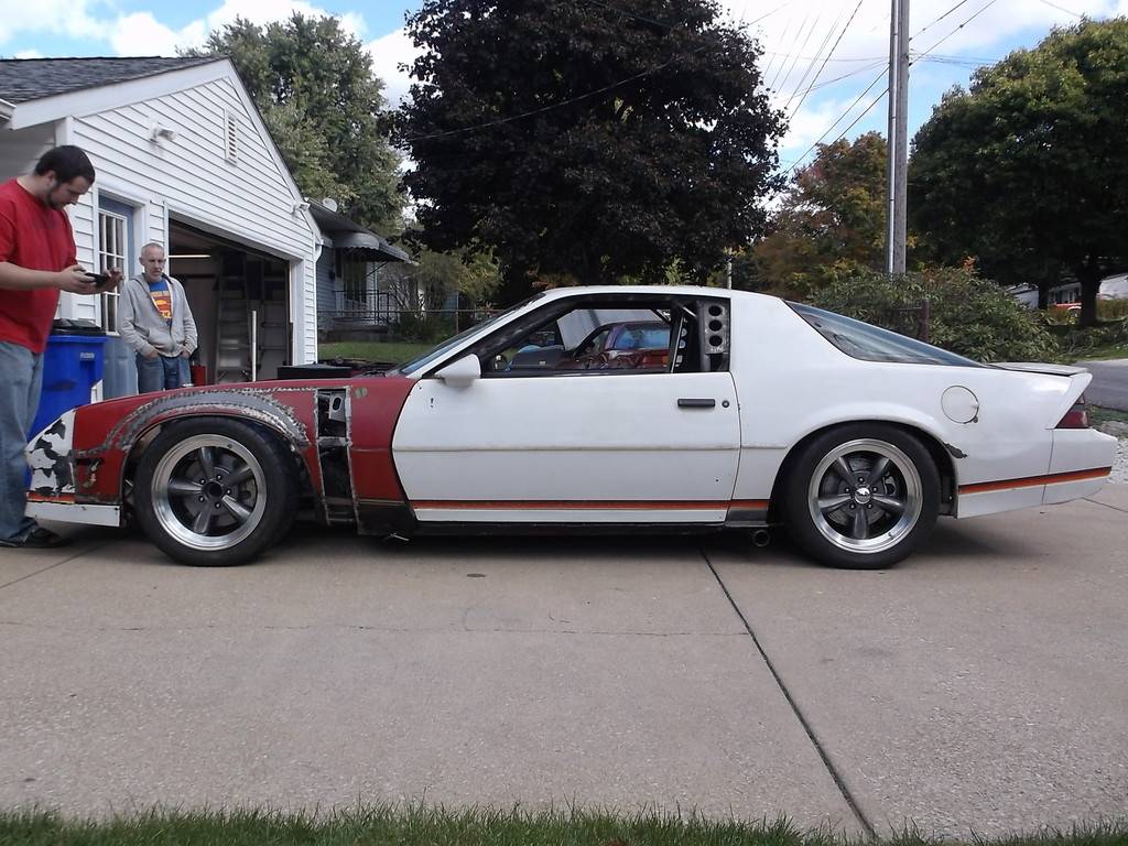
My friend Devan is the big guy in the red shirt. He is about 6'3" and makes the car look really low. I got out my 4' level and set it up on the highest part of the roof. Devan measured the car height at 47 1/4". Once I get the ride height reset I should be right around 48".
a few more driveway pics.
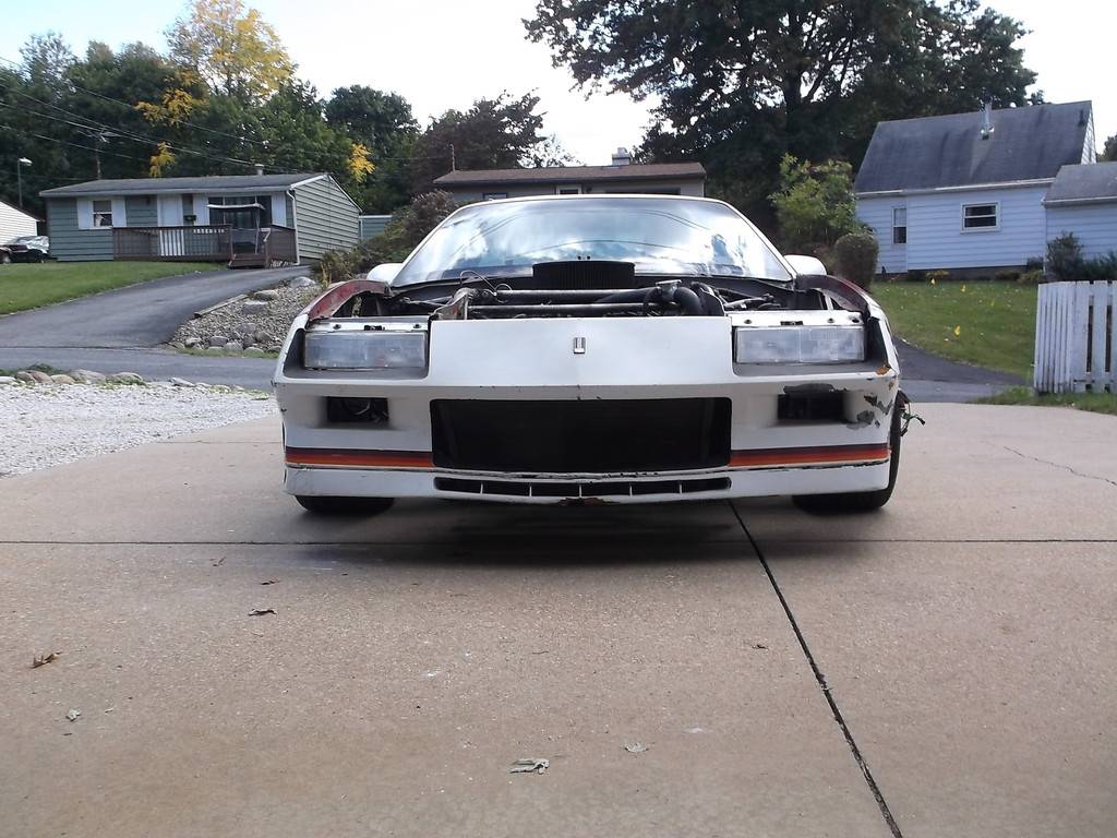
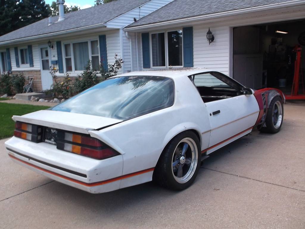
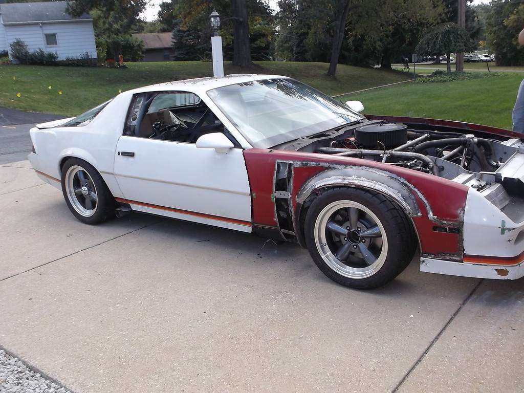
I couldn't wait any longer and had to take for ride around the block. The body is nearly sitting on the tires and the bottom of the front fenders are held in with C-clamps but I have to drive it. I tell my other buddy Craig to hop in and off we go. https://www.youtube.com/watch?v=bfbSnug0F9g That little drive made 6 years of effort all worth while. The engine ran great, the steering felt real good and the brakes worked very well, not needing any extreme effort to stop. I am sure there are plenty of bugs to work out the more I drive it but the fact it made its maiden voyage with no real problems was very encouraging. WOOHOO!!!!
-
10-13-2016 #100
Registered User
- Join Date
- Jul 2011
- Location
- Prescott, AZ
- Posts
- 206
We're happy to see it running!! Its giving off a mad max feel with the raw metal and missing body panels, which is pretty cool.


 Reply With Quote





