


Results 21 to 40 of 138
Thread: 3rd gen Z28 track day build
-
09-12-2015 #21
 Registered User
- Join Date
- Jun 2015
- Location
- kent,ohio
- Posts
- 128

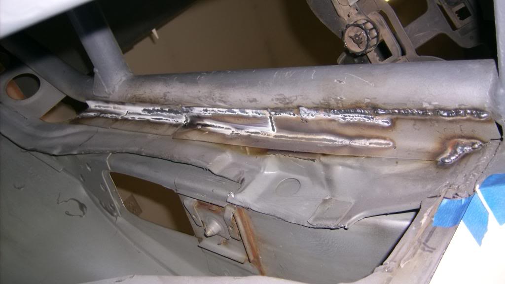
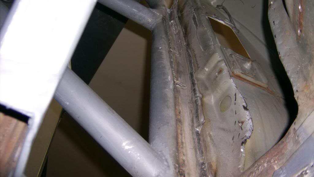
Because the rear of the main hoop is the end of the interior The gaps between the main hoop and the inner body panels had to be sealed off. I bent up long strips of 18ga and stitch welded them to the body and main hop. What a PITA!!!!!!!!
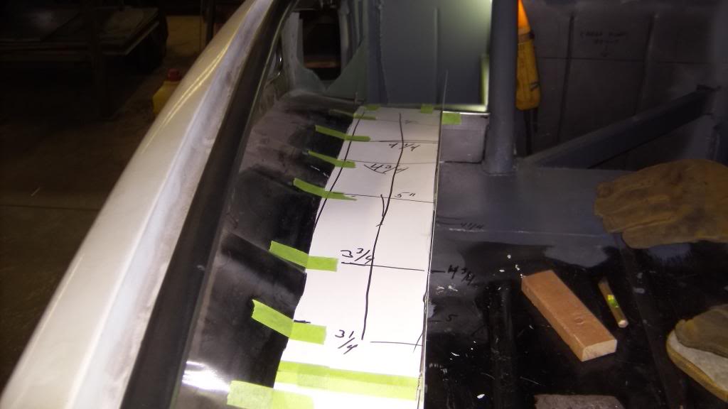
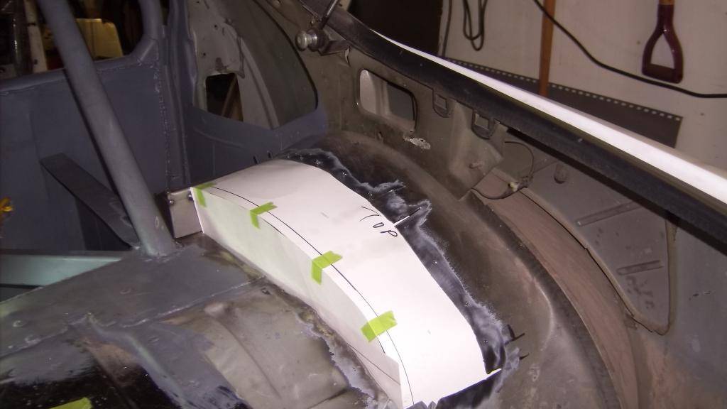
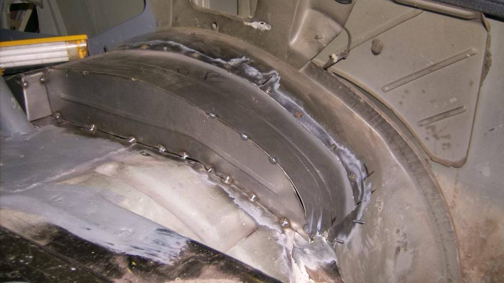
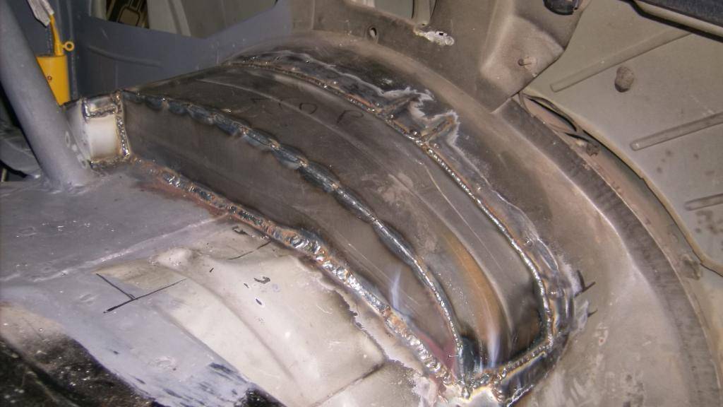
next was to make new wheel tubs. I left most of the factory tub intact and just added what I needed. Still a big job and many many feet of weld.
again, templates to steel part.
Driver side
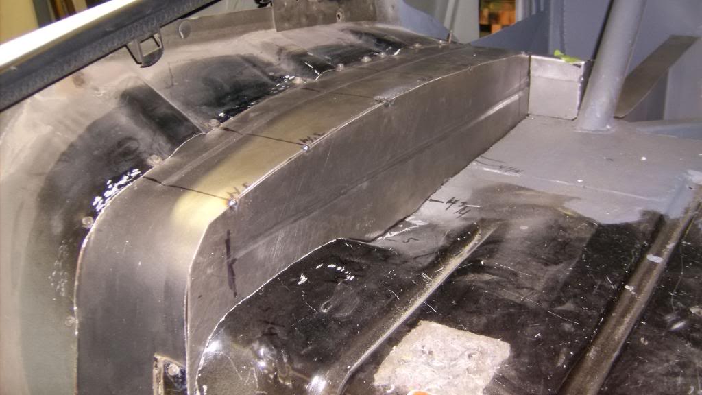
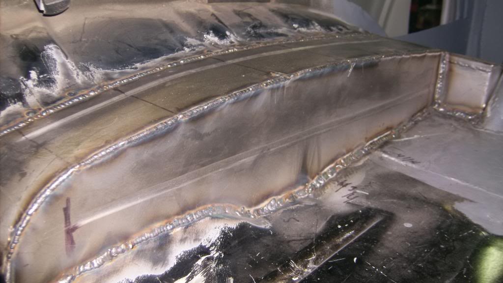
Passenger side
-
09-12-2015 #22
Registered User
- Join Date
- Jun 2015
- Location
- kent,ohio
- Posts
- 128
With the tubs done next was making a rear floor extension to cover the area where the rear seat used to be.
added a center brace.
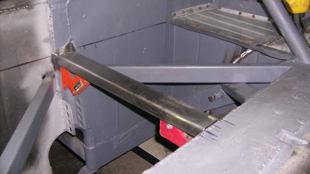
again 18ga sheet steel
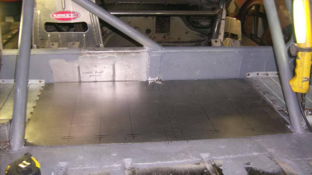
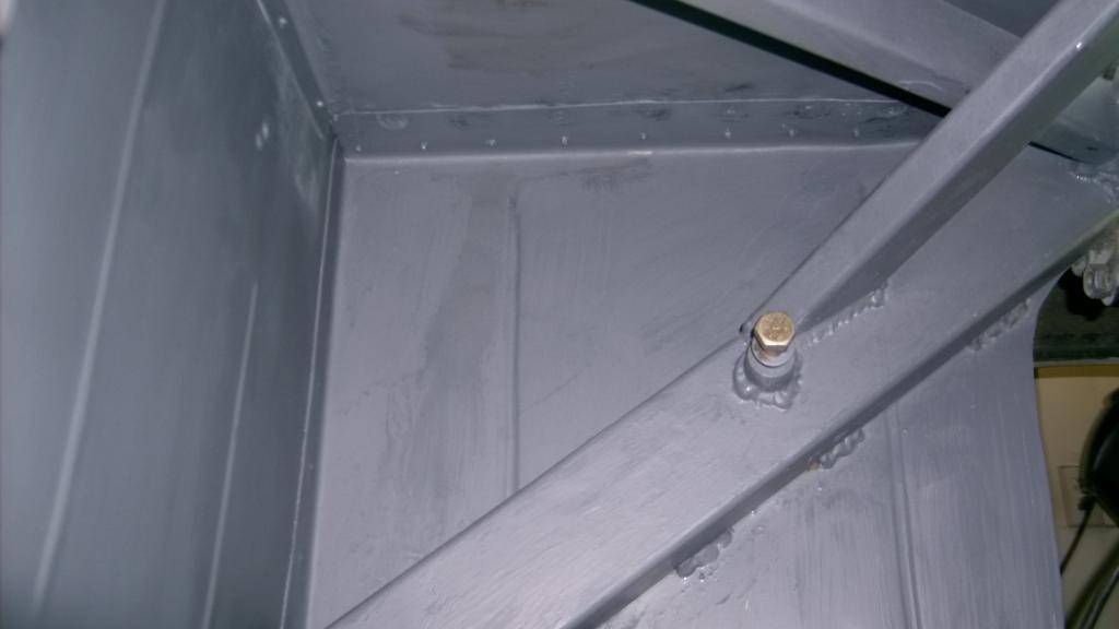
added stiffening beads and welded and primered. Finished rear floor and wheel tubs.
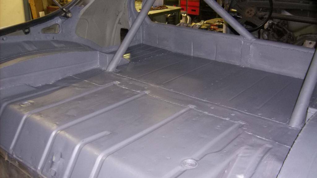
from underneath
rear firewall
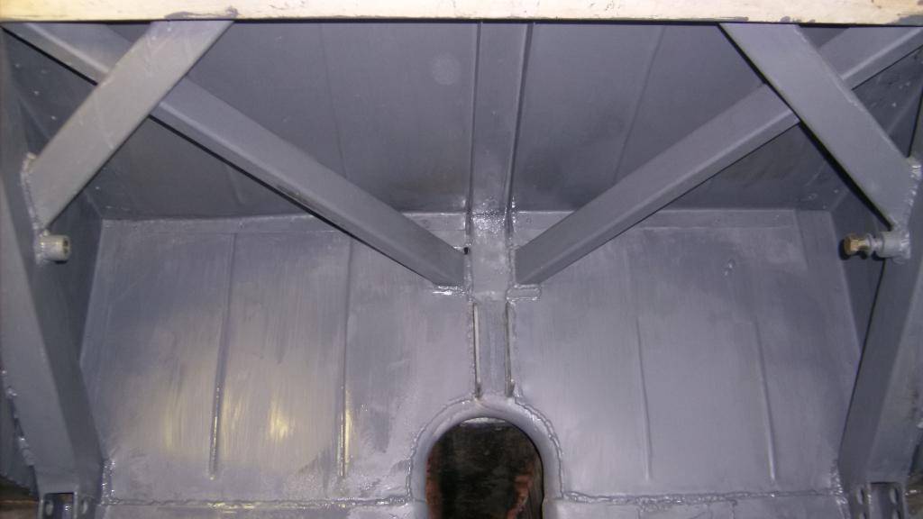
back side of inner wheel well
09-21-2015 #23
Registered User
- Join Date
- Jun 2015
- Location
- kent,ohio
- Posts
- 128
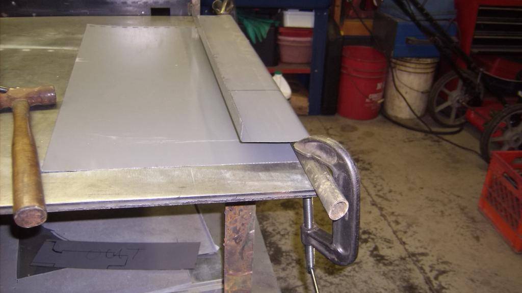
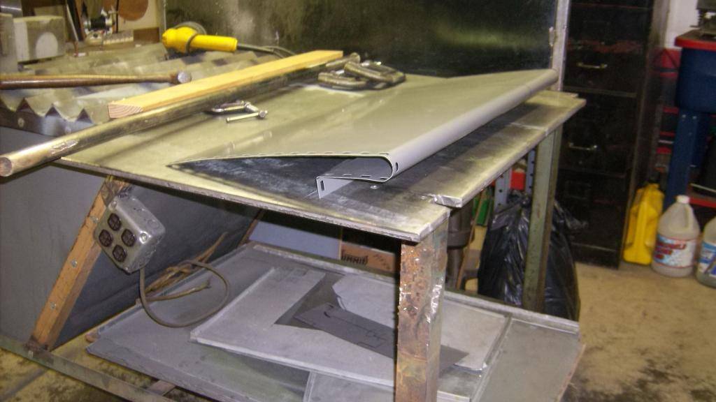
with the rear sheet metal done I moved on to making a new dashboard.. I wanted something simple but it had to have a dash pad that over hung the gauges by a couple inches to keep them from reflecting onto the windshield at night. I had an abundance of .028 sheet steel so that is what I made it out of.
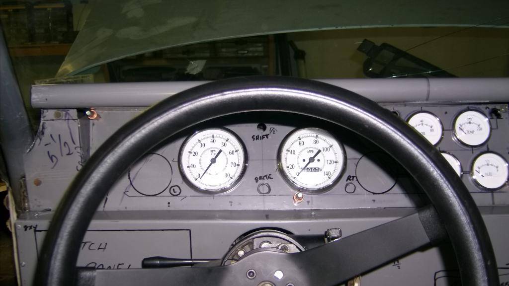
I wanted the 4 auxillary gauges grouped in one cluster so at one glance I could see oil pressure and water temp. This was initial placement.
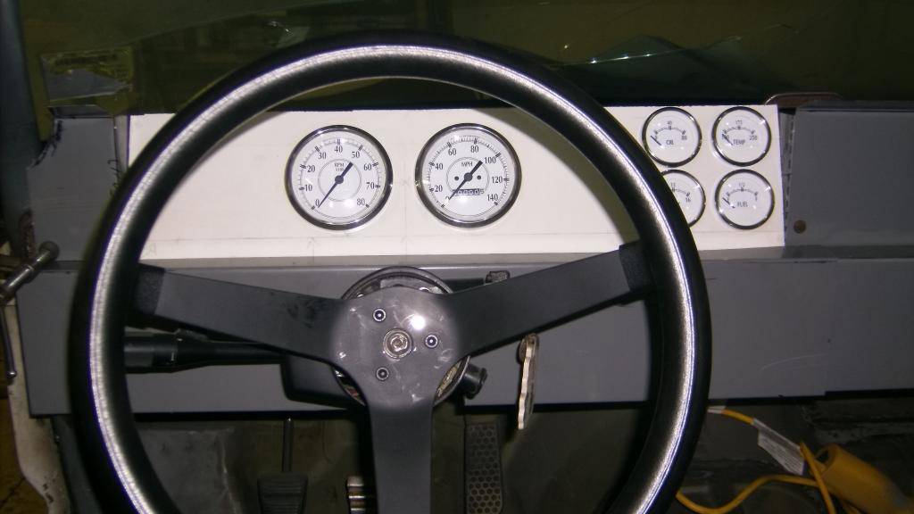
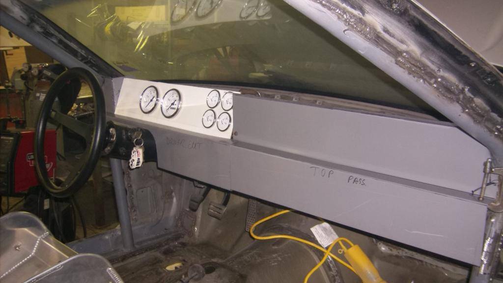
slight redesign made room for warning lights for oil and water.
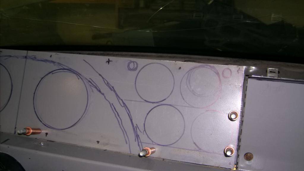
making top of dash
Gauge cluster from drivers view. i still have room for a couple more auxillary gauges, probably an O2 gauge will find its way into one spot.
and overall view. I still have to make pieces to go around the cage at A pillars but that will hapen when I take the windshield out.
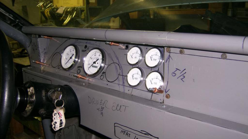
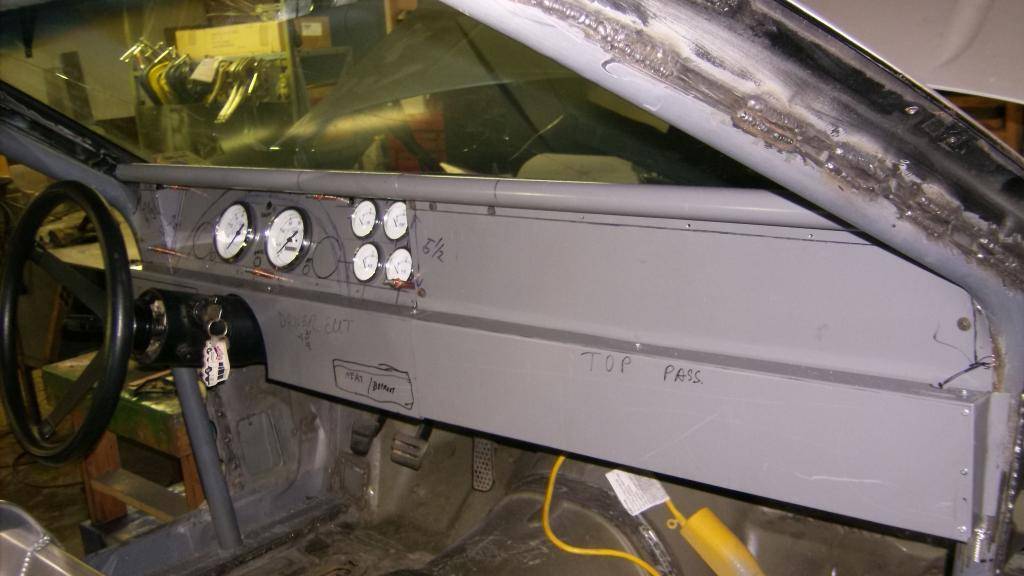
as you can see there is a lot of empty flat surfaces at center and right side. Plenty of room for HVAC controls and audio. Also could put in some type of glove box or a dropout panel for ignition box and electrical. I purposely kicked the bottom half of dash out 1 1/2" to make it easier to reach any dash mounted switches or controls when strapped in with 5 point harness.
09-21-2015 #24
Registered User
- Join Date
- Jun 2015
- Location
- kent,ohio
- Posts
- 128
Now for the biggest challenge, adapting the front suspension from a 2000 LS1 Camaro onto the stock frame rails. I have looked at hundreds of post on the thirdgen.org web site about owners wanting to do away with the strut front end and adapting some type of short/long a-arm type of suspension. They also wanted power rack and pinion steering and larger disc brakes. I figured if I could get the 4th gen Camaro front end to work I could get all of these upgrades in one package.
The other reason that I personally wanted from this conversion was to correct the terrible front/rear weight distribution. This car scaled out before I did any work to it at 3208lbs without the driver and minimal fuel in the tank. It was a true 60/40 car with 1900lbs on the front and 1308 on the rear wheels. The most common way to address this is to move the engine back 2 or 3 inches or swap in an all aluminum LS1 engine. Some do both. I wanted to keep the engine in the stock location to make it easier to service ( I hate working on engines half buried under the cowl/windshield) and the firewall intact for fire protection and structural integrity.
My solution to correct the weight distribution problem was to move the front spindle center line 5" forward. This moves almost the entire weight of the car rearward 5" in relation to the front wheels. Instead of moving 650lbs rearward 3" I can move 3000lbs back 5". I am hoping for a final weight distribution of 52/48 or better when I am done.
I looked at many different spindles before I settled on the 4th gen, I chose it mainly because of its very tall spindle. Like the 3rd gen suspension the upper control arm mounts to the top of the inner fenderwell. The tall spindle will allow the upper control arm to mount high enough to clear the factory frame rail at a full 3" suspension drop. Once I had decided on the 4th gen front end I found spindle measurements on the web and made a scale drawing of it positioned along the 3rd gen frame rail. With a planned ride height of 5" everything looked like it would fit, some assembly required!!!!!!!!
Here we go. I was able to buy a complete k-member with suspension, brakes and steering from a local pick a part for $150.
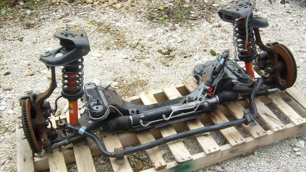
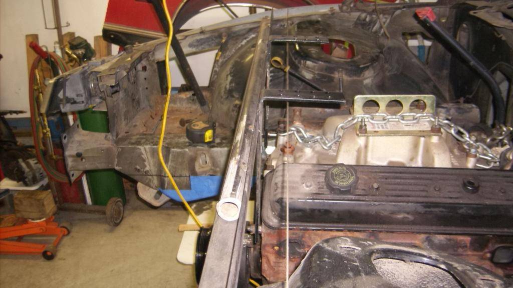
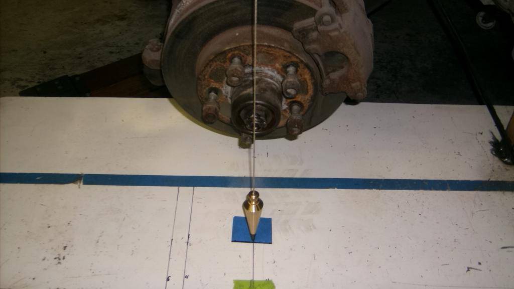
i used a plumb bob to mark the stock spindle location and then removed the stock suspension. Before I could remove the k-mamber I had to hang the engine from above to keep it in its stock location.
I stripped the 4th gen k-member down to just the lower control arms, spindles and steering rack and propped it up under the car for a test fit. The first problem to come up was with the car lowered more than 3 inches from stock the k-member was too tall. I ended up cutting the top of the k-member off just above the lower control arm mounts.
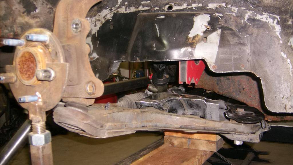
This brought up a second and more serious problem. The rack and pinion was positioned to pass through the harmonic damper! In all of my drawings, side view and front view, I plotted the tie rod attachment to the spindle and the crankshaft center line, but never drew a line to connect both spindles. Center line of the tie rods was about 3/4" below the crankshaft center line.
This is with k-member sitting about 3" lower than where it needs to be.
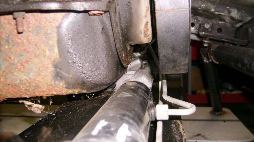
I was really bummed. After looking for a workable solution I came across a Flaming river rack kit for an early 60's impala that mounted the rack ahead of the tie rods and used a centerlink of sorts, mounted behind the rack, to get the tie rods back into position. I figured I could adapt something like that to the Camaro rack so I continued on.
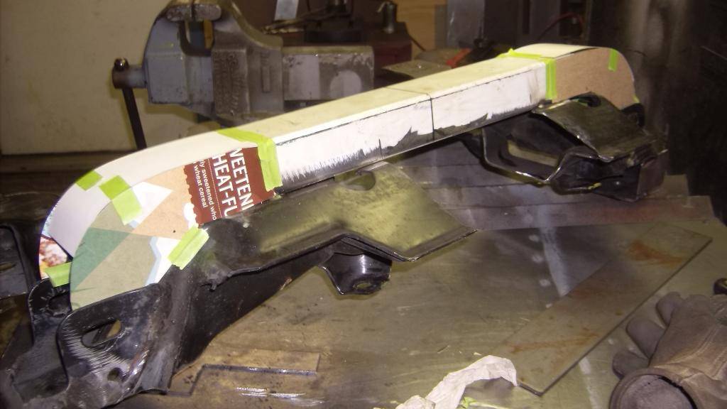
To get the 4th gen k-member mounted high enough in the 3rd gen frame for proper lower control arm angle I also had to cut out the center of the k-member. Before I did this I welded a length od 2x3 tubing to the bottom of the k-member This literally cut the k-member in half and made the bottom side now the top side.
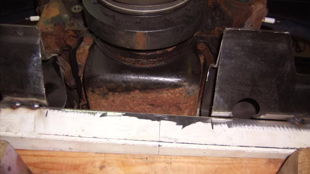
Factory rack mount beside harmonic balancer.
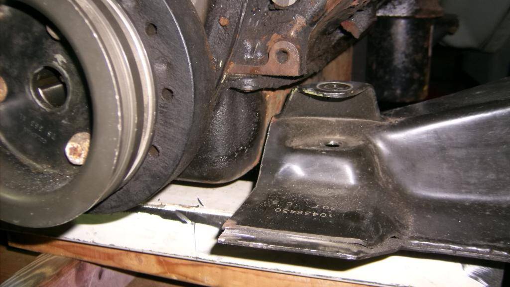
It took several hours to get the cut down k-member squared and centered in the chassis. There is no symmetry what so ever on a 3rd gen. The frame rails are offset to the right about 1 3/4" and the engine is also offset to the right about 3/4" inside the frame rails so finding the true center line of the car (center of track width) took a little work Once I had the k-member centered I welded some small tabs between the frame an k-member to hold it in place.
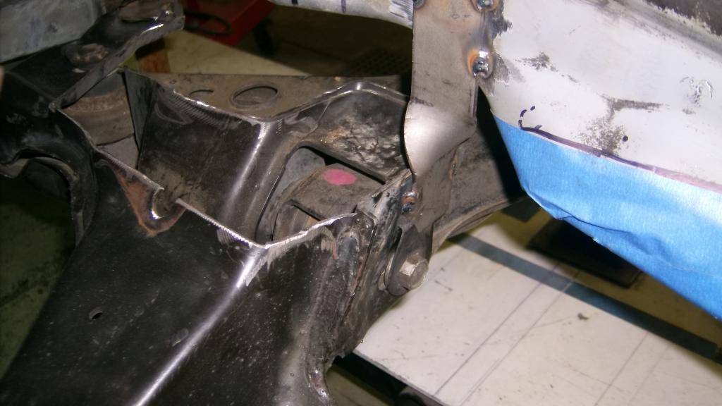
09-21-2015 #25
Registered User
- Join Date
- Sep 2015
- Location
- SW KS
- Posts
- 162
Whoa! That's serious!
Good luck!
Chris
09-21-2015 #26
Registered User
- Join Date
- Jun 2015
- Location
- kent,ohio
- Posts
- 128
Chris, thanks for checking in. Yeah it is a big project, 5 years this November. I had big ideas a small budget and not a lot of fancy equipment, but we are getting it done, solving one problem at a time.
09-21-2015 #27
Registered User
- Join Date
- Jun 2015
- Location
- kent,ohio
- Posts
- 128
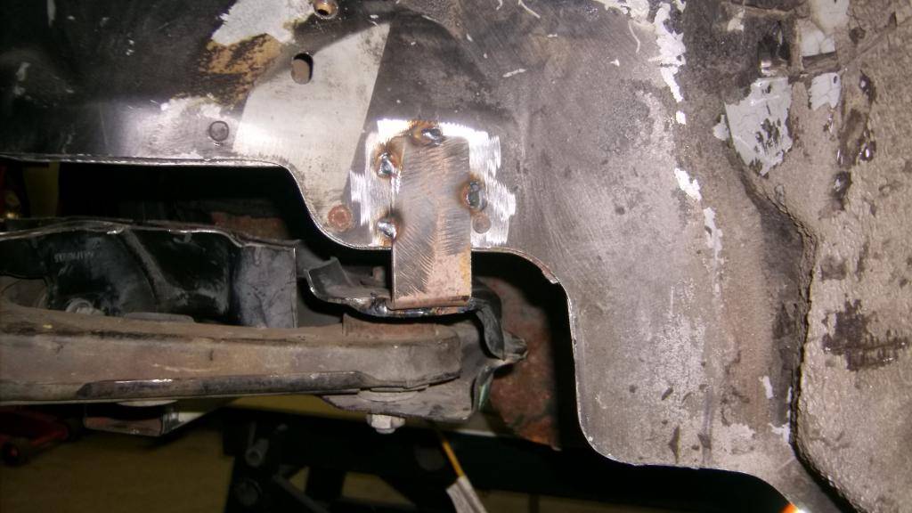
the cut down LS1 k-member fit in the mounting space of the 3rd gen k-member so it was an easy decision to make it bolt in to the factory locations. I made 6 separate mounting plates of 3/16 steel (remember no symmetry) that fit in the pockets in the bottom of the frame rails. Then I started connecting the mounting plates to the LS1 k-member with pieces of 1/8 steel sheet. I tacked on as many pieces as I could get the welder into.
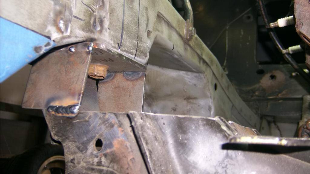
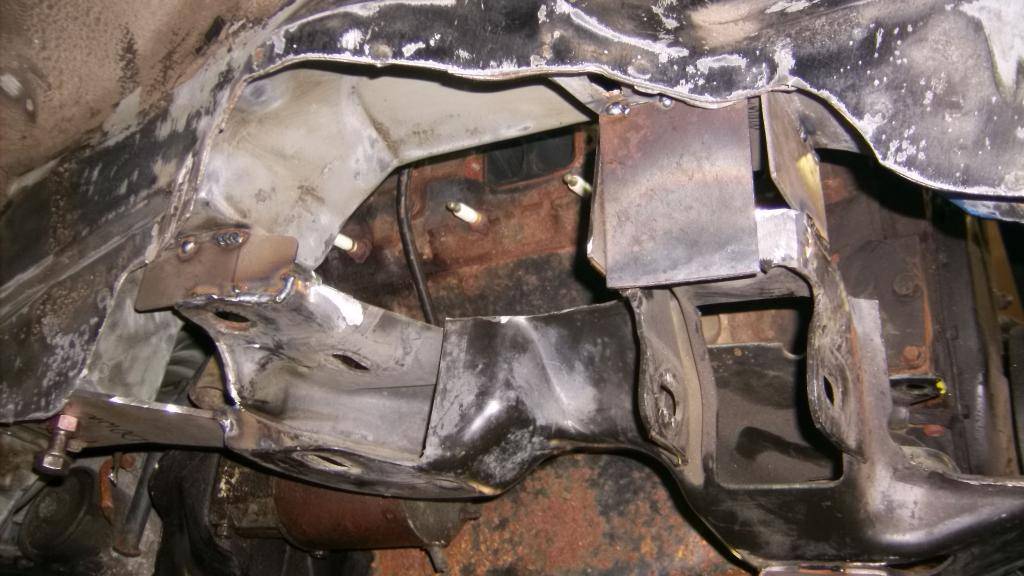
because the caged nuts up in the frame can move a 1/4" in any direction I had to make sure my new k-member always bolted back in the same place. I added these 1/4" bolts to the rear mounts on both sides. The holes are close tolerance so once they line up it is all good.
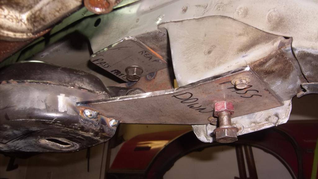
I pulled the k-member back out it looked like this.
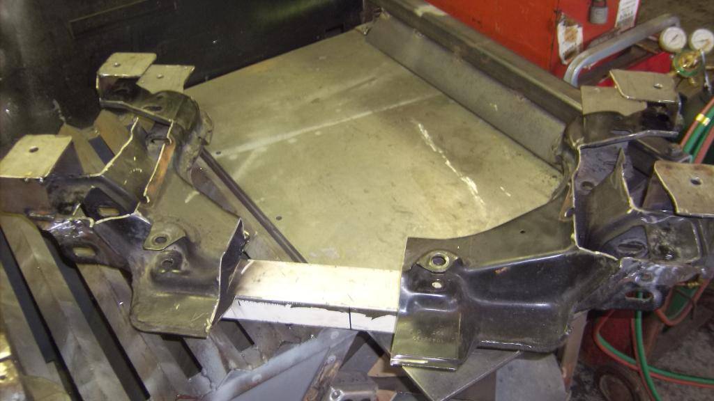
I have to admit it was the most hokey, cobbled together piece of c**p I have ever made, but I had a plan and if it worked out this pile of scrap metal would be the key to getting the suspension under the car. Here is how it came together.
This would be the new "bottom" of the the k-member
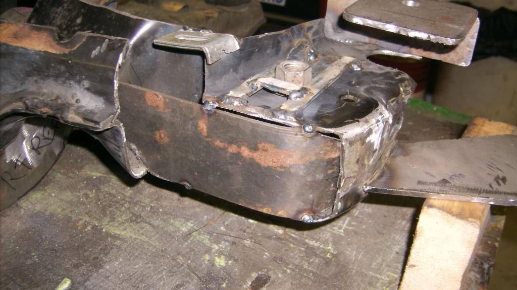
The rear control arm mount protruded into the engine bay quite a bit and caused header clearance issues. Cut out the stamped metal and replaced with 1/8 sheet. Gained about 1 1/2". You can also see where I took the factory flange nut that secures the lca rear bushing and caged it in. It can slide back and forth the width of the factory slot but can't spin around. This nut will be inaccessible when the k-member is finished.
Front end caps
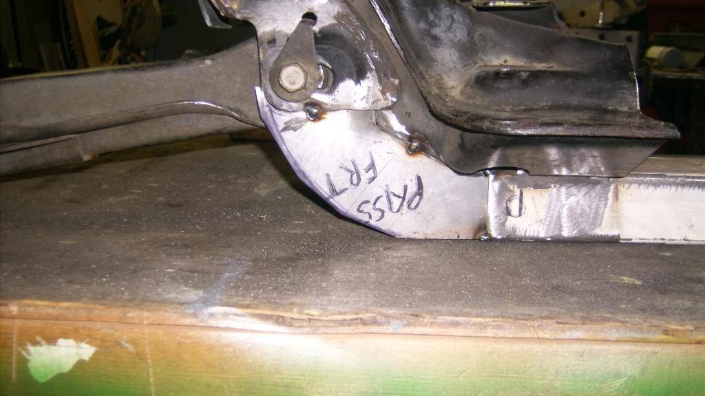
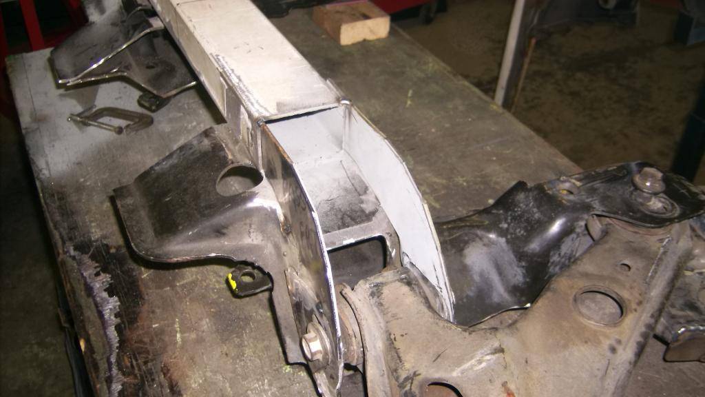
The rear lca mount wasn't supported by much after the top of the k-member was cut off so I added these 1x2 braces. Not sure if they will stay when all is done.
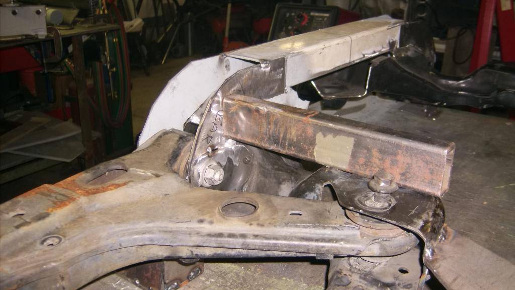
clearance check
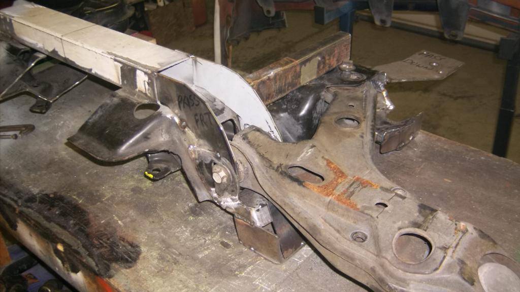
ideas for more bracing and engine mounts
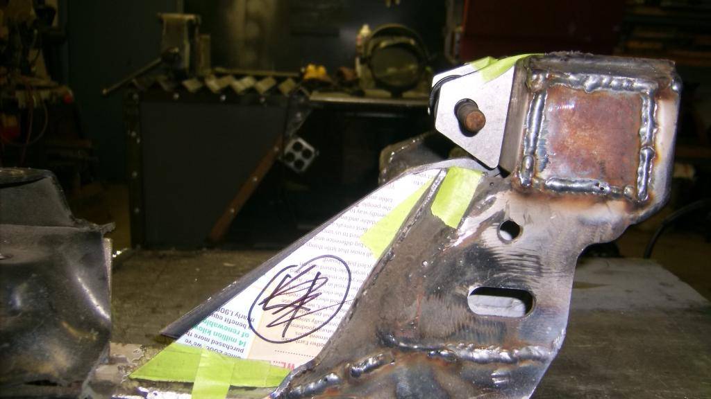
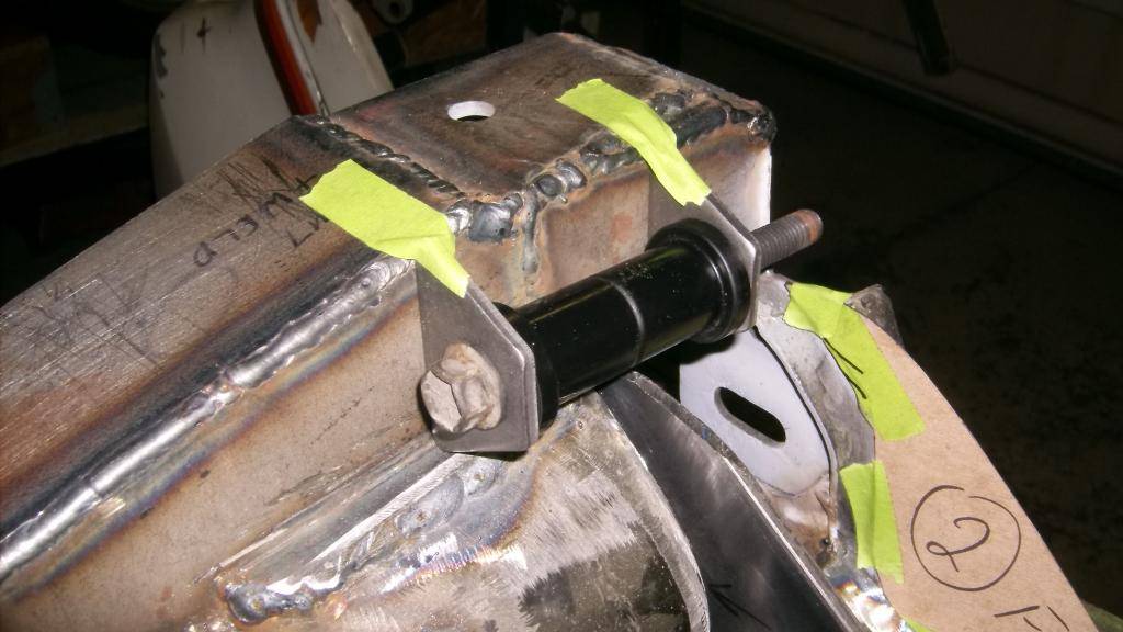
not completely done but this is basically what it will look like.
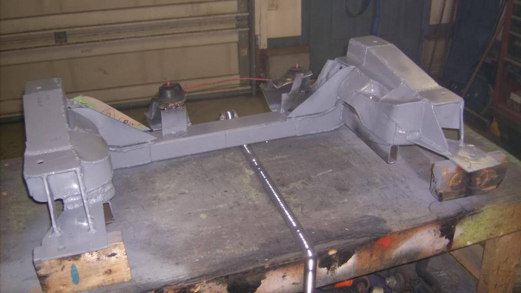
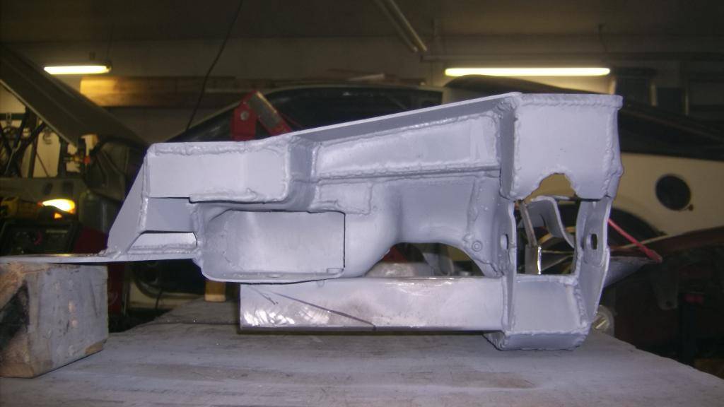
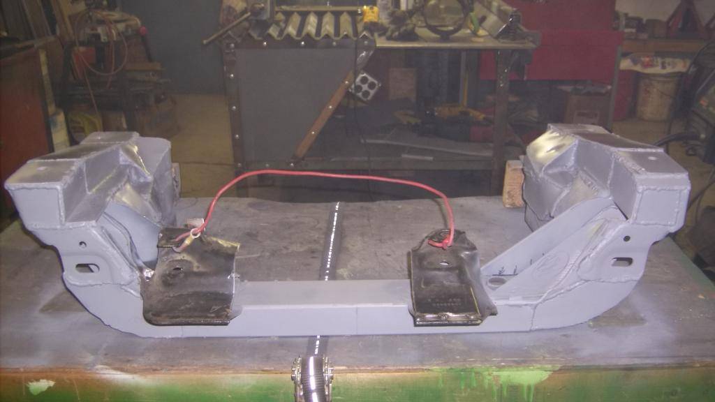
I kept the factory rack mounts to use as a guide to help me mount the rack in front of the crank pulleys. The new k-member is very stiff. Tighten any one of the four front bolts and the whole K-member pulls tight to the frame. Strength and not weight was the primary consideration when making this. Out of curiosity I put it on the scales and it weighed 46lbs, a pound or two heavier than the 3rd gen and a little less than the 4th gen. Now that I have a good pattern I could probably shave 10lbs off if I made it from scratch out of 1/8 and 3/16 steel plate, even lighter if tubing but I don't have a bender.
09-21-2015 #28 Registered User
- Join Date
- Dec 2006
- Location
- Out of the Burbs of Detroit to SoCal, then onto my ancestral homeland, the woods of Cascadia
- Posts
- 1,753
What I'm really liking is that having recognized the limitations of the Strut front end, you are change to SLA instead of doctoring the strut to try to get the best from a clearly compromised design.
Good thinking. I may steal... er, appropriate some of your ideas for the Capri or FoxstangGreg Fast
(yes, the last name is spelled correctly)
1970 Camaro RS Clone
1984 el Camino
1973 MGB vintage E/Prod race car
(Soon to be an SCCA H/Prod limited prep)
09-25-2015 #29
Registered User
- Join Date
- Jun 2015
- Location
- kent,ohio
- Posts
- 128
Greg, thanks for posting. Your last name could be a blessing or a curse. Originally Posted by Twentyover

The stock 3rd gen suspension can be made to perform very well even with all of its shortcomings, but I wanted something different and I wanted to correct the terrible weight distribution. We'll see how well my idea works out next summer when it SHOULD be road worthy.
Dave
09-30-2015 #30
Registered User
- Join Date
- Jun 2015
- Location
- kent,ohio
- Posts
- 128
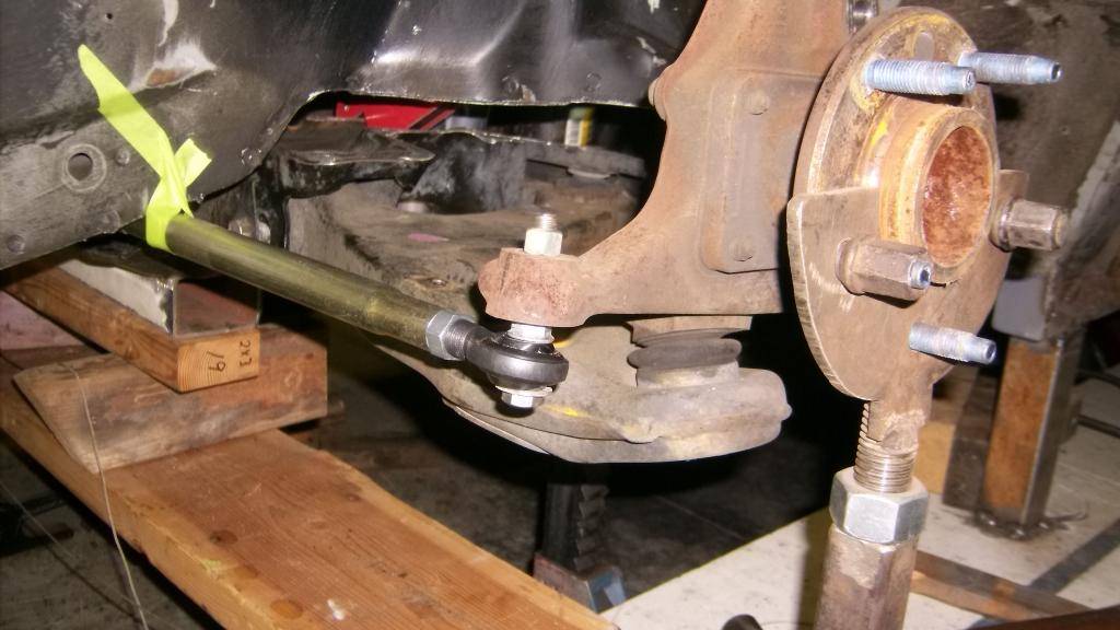
Because I was not 100% sure the 4th gen front suspension would actually work in the car I wanted to at least get the lower a-arms and spindles fitted in place and the rack and pinion before I cut out the stock wheel wells or cut on the frame rails. I was able to hold the top of the spindle at a base alignment of 6* positive caster and 0* camber.
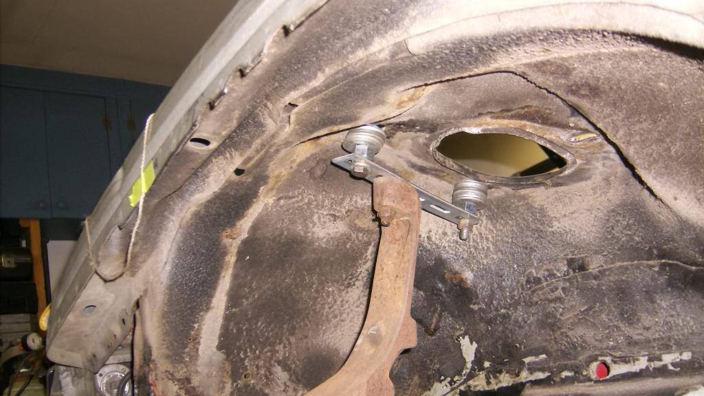
This let me mock up the new tie rod location. I wanted the tie rod to sit horizontal and run parallel to the line from lower ball joint to lca pivot bolt to minimize bump steer.
Then had to mock up the rack. This had to sit forward of the crank pulleys at its stock height.
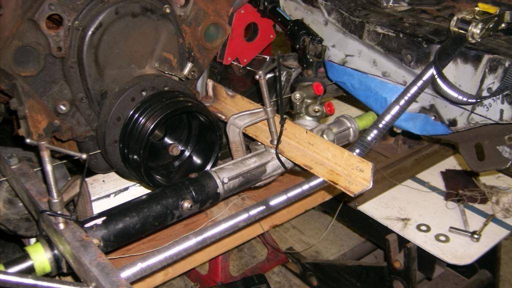
here you see things lined up pretty well.
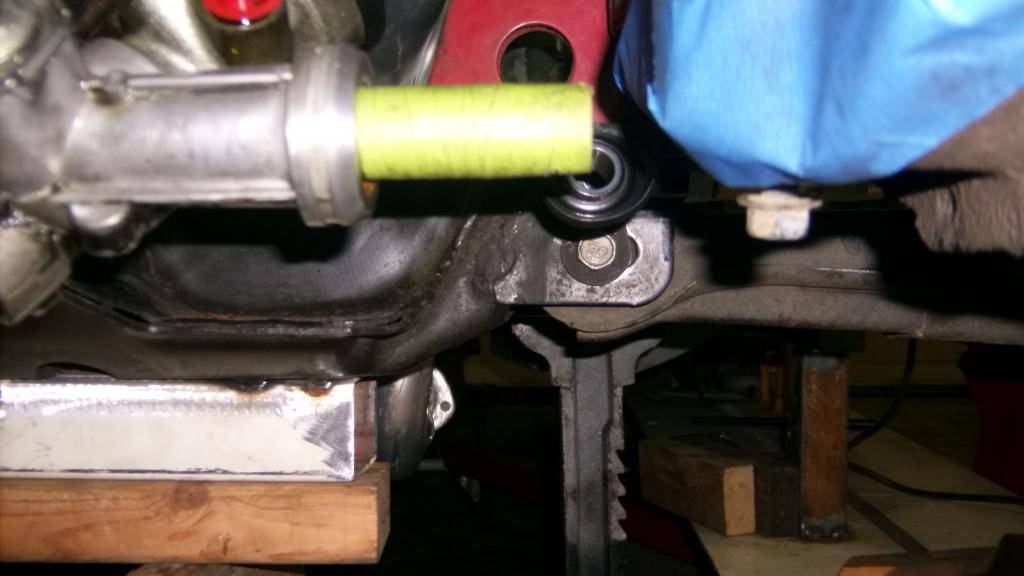
With the rack in place I came up with this plan to reattach the tie rods to the rack.
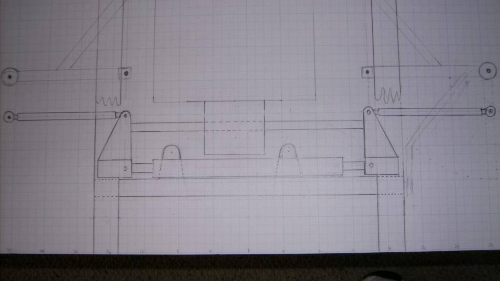
The triangle pieces would be about 5 inches long extending from the rack back to the OE position of the tie rods. This would put a lot of bending force on the rack that it wasn't designed for. I added a drop style centerlink between the two triangular pieces to try and prevent as much bending or deflection in the rack as possible.
09-30-2015 #31
Registered User
- Join Date
- Jun 2015
- Location
- kent,ohio
- Posts
- 128
With a plan in place I had a local machine shop make adapters for the ends of the rack.
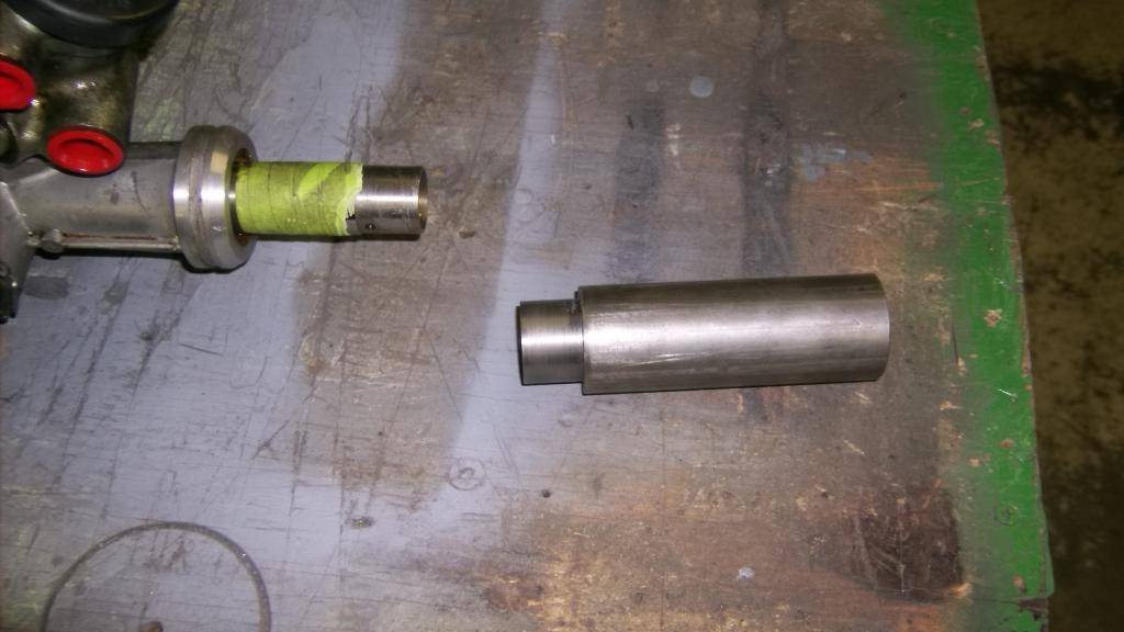
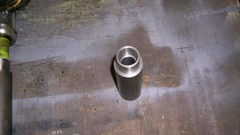
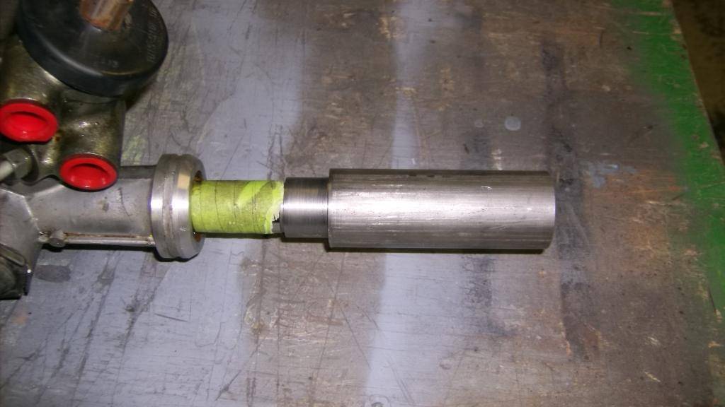
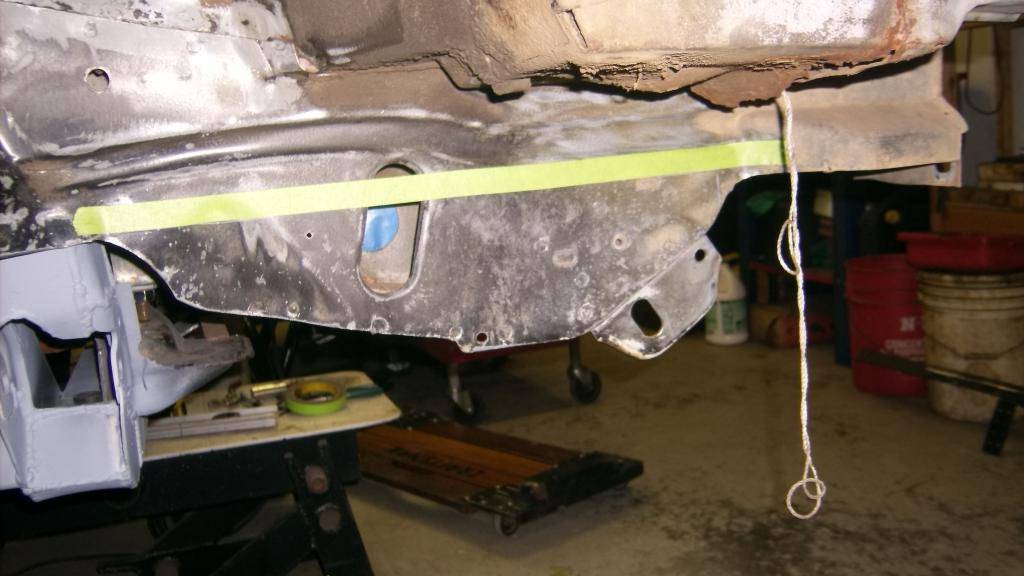
Here is where I had to take a leap of faith and make a major modification to the front frame rails. No turning back now!!!!!!!!
Everything below the tape had to be cut out.
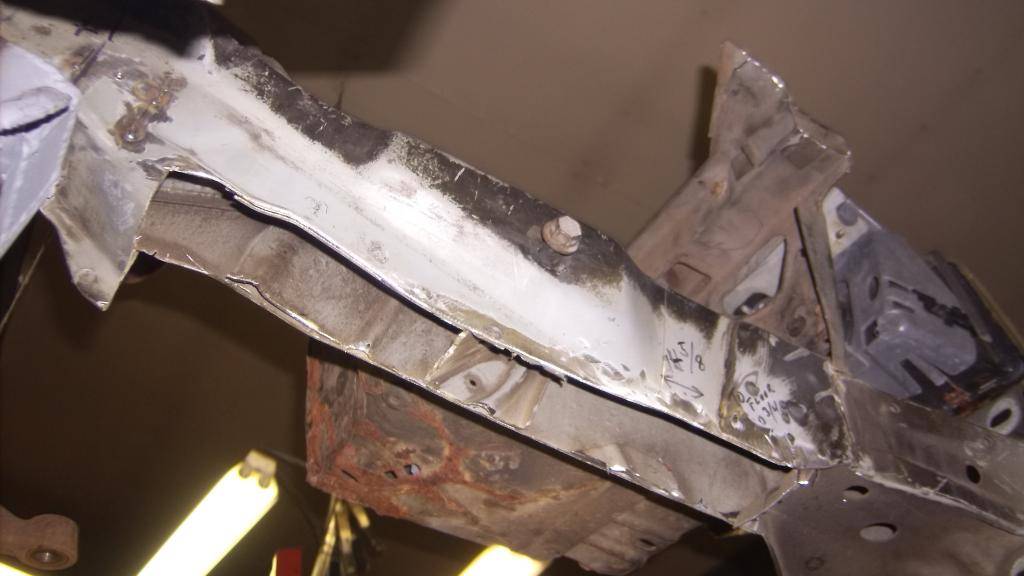
I replated the bottoms with 3/16 plate and took great care that both sides were level with each other and parallel.
this gave me about 2" clearance for the rack to travel under the frame.
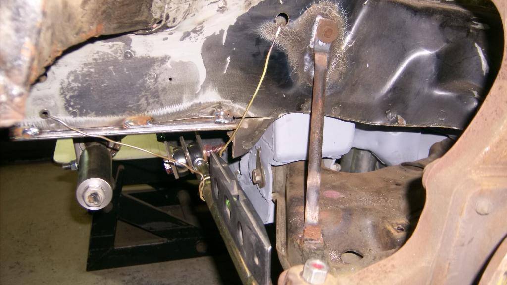
09-30-2015 #32
Registered User
- Join Date
- Jun 2015
- Location
- kent,ohio
- Posts
- 128
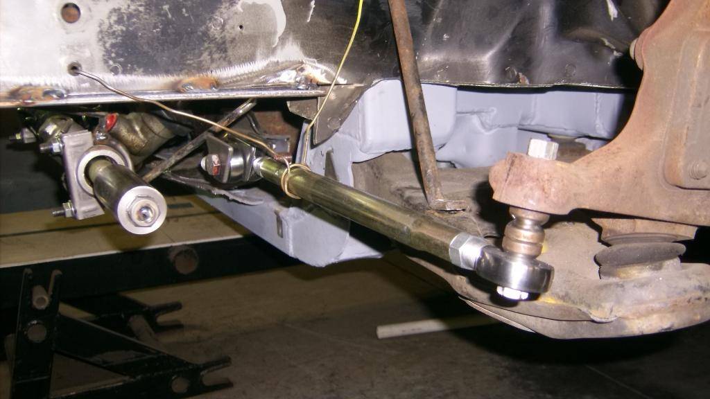
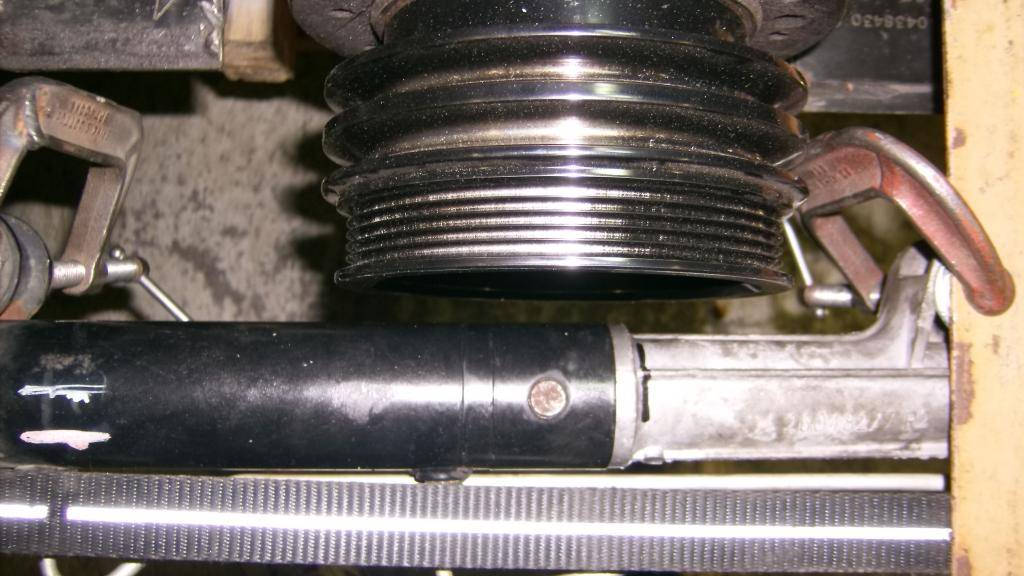
I had been holding the rack in position with angle iron and c-clamps but it was cumbersome and did not allow for any adjustments. It also was in the way of the factory mounts on the rack so a new way of holding the rack in position was needed.
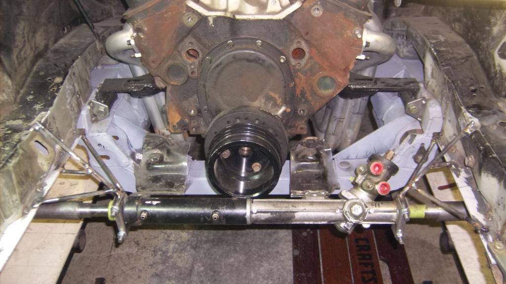
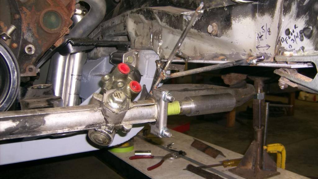
This temporary mount allowed me to hold the rack securely in position and let me rotate it to get the best angle for the steering shaft.
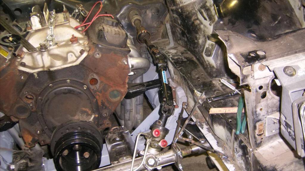
Tie rod and rack alignment.
Crank pulley and rack clearance. Just enough to get a v-belt through. Can also remove pulleys and damper with rack in place.
09-30-2015 #33
Registered User
- Join Date
- Jun 2015
- Location
- kent,ohio
- Posts
- 128
Installed headers and built motor mounts and set location of steering shaft.
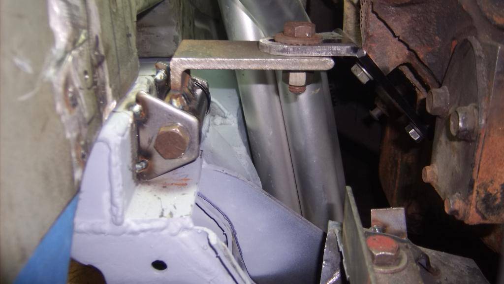
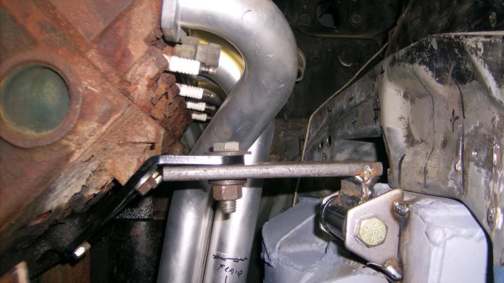
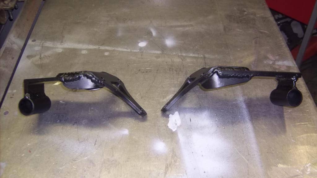
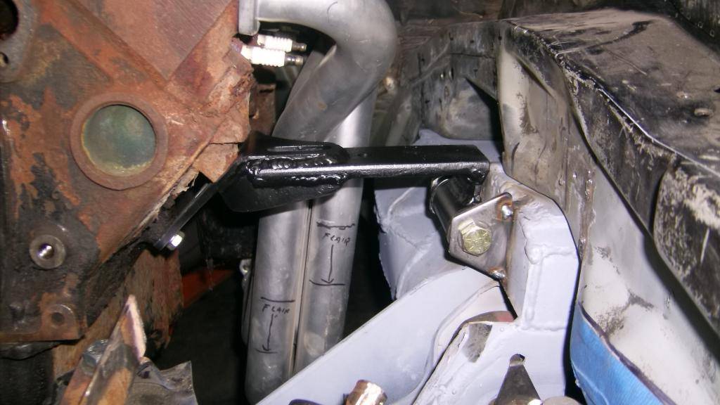
I found that rotating the rack input shaft towards the rear and down some eliminated any binding in the u-joints.
09-30-2015 #34
Registered User
- Join Date
- Jun 2015
- Location
- kent,ohio
- Posts
- 128
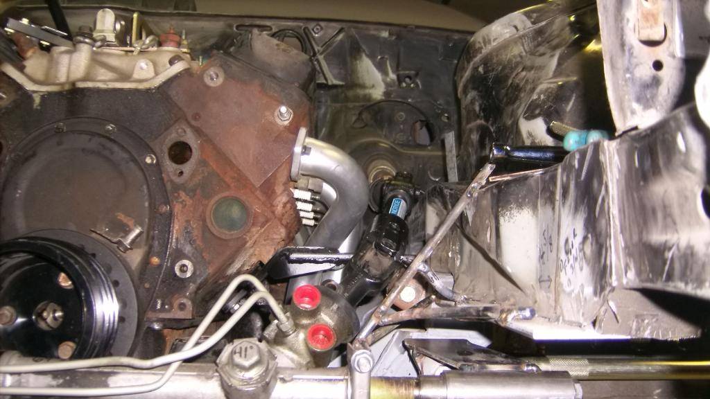
With everything set in place I set about reconnecting the tie rods to the rack.
Bridge plates are 1/4 steel.
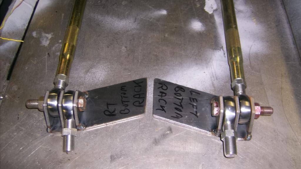
Center of tie rod to center of rack is 5"
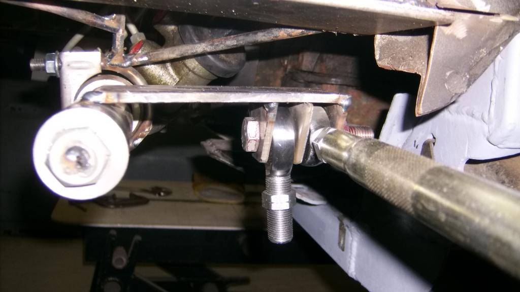
Every efort was made to make sure the rack and tie rods were level and parallel. Also although close the bridge plate clears the rack housing at full lock.
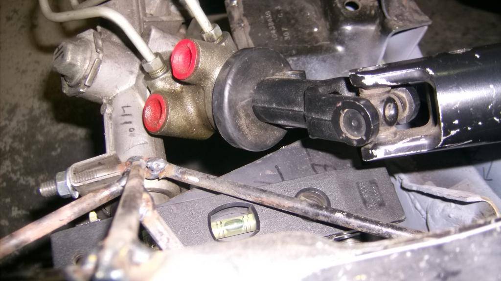
Good picture of how all steering parts fit around frame, engine and chassis.
10-02-2015 #35
Registered User
- Join Date
- Jun 2015
- Location
- kent,ohio
- Posts
- 128
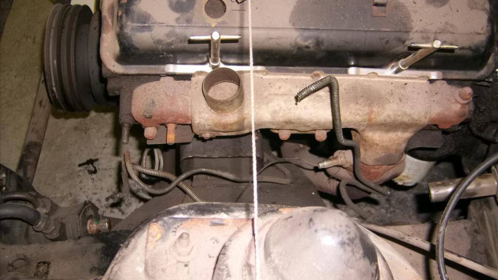
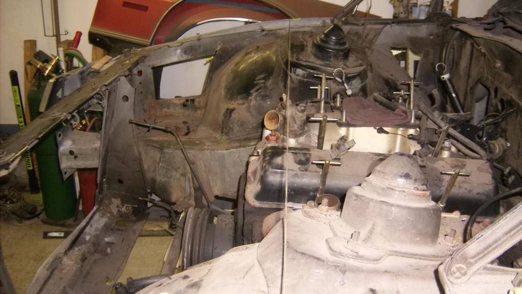
Here is a good comparison of just how far forward the front wheels have been moved. I had originally planned to move the front wheels 4" forward but had to go 5 inches to get rack to clear pulleys. This gives me a wheel base of 106" on a car that is 192" long.
Stock spindle centerline in relation to engine.
And with centerline at 4" forward. No picture at 5" final placement but string would be at top forward edge of valve cover.
Hopefully the change in weight distribution and improved balance and handling will make it worth all the effort.
10-02-2015 #36 Registered User
- Join Date
- Feb 2015
- Location
- Ladera Ranch, CA
- Posts
- 25
Wow!! That's quite a build!! Nice work!! Keep the pics coming!!
10-02-2015 #37
Registered User
- Join Date
- Jun 2015
- Location
- kent,ohio
- Posts
- 128
I took another lead of faith and cut out the front half of the wheel well to allow the steering to turn lock to lock and check clearances.
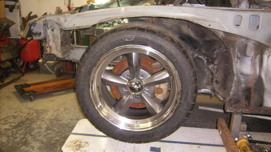
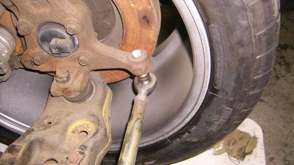
Plenty of room for a Spohn bump steer kit.
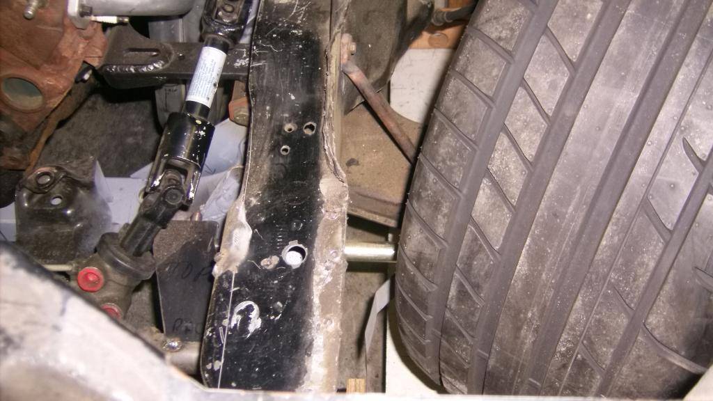
Also room for wider rim/tire package. I would like to go 18x11 w/8" back space and a 315/35/18 tire at all 4 corners.
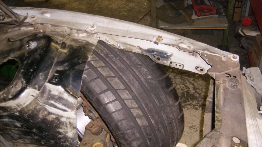
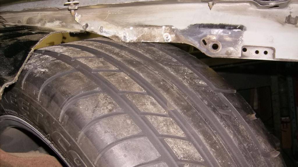
To get 2 1/2 to 3" of compression travel in a turn the upper frame section will have to be removed as well as the entire wheel well.
10-10-2015 #38
Registered User
- Join Date
- Jun 2015
- Location
- kent,ohio
- Posts
- 128
to mount the rack I decided to make a new front crossmember that would also serve as the rack mount and splined swaybar mount.
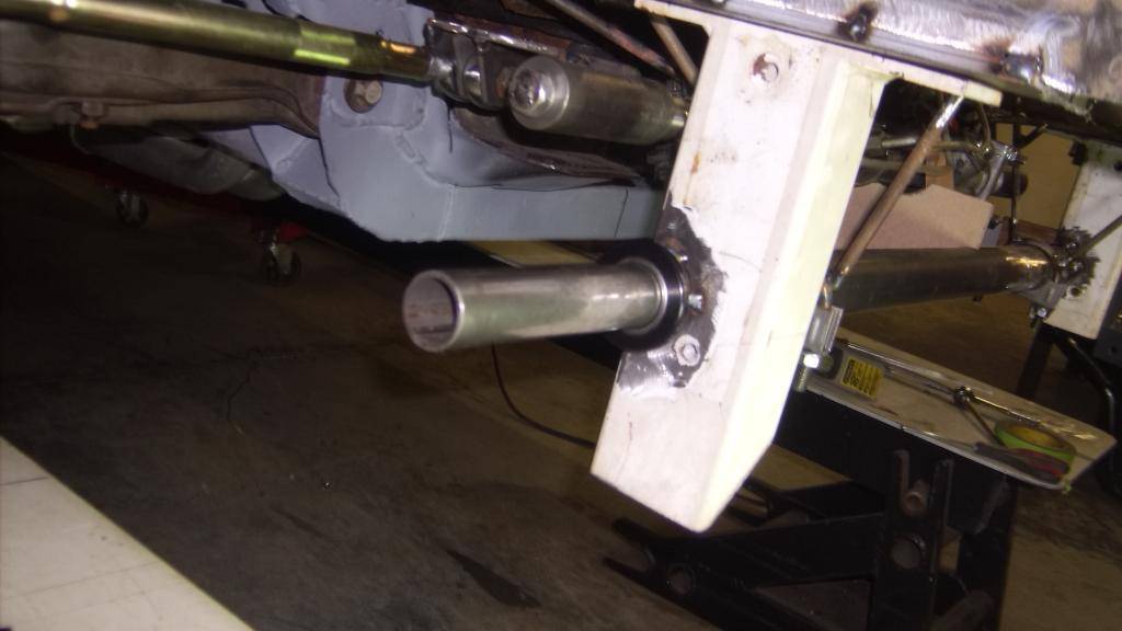
mock up of sway bar and arm.
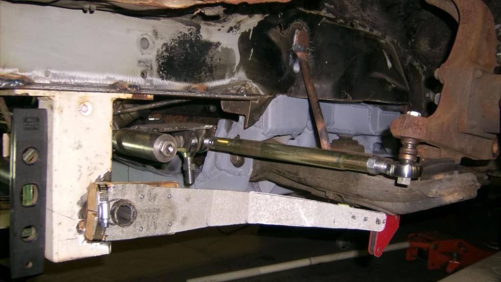
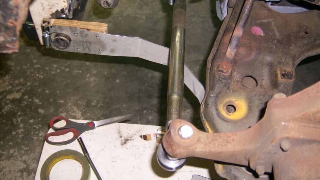
start of cardboard rack brackets
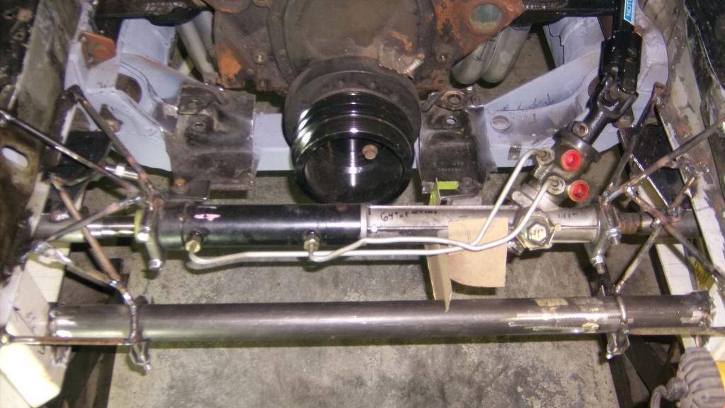
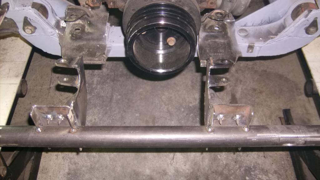
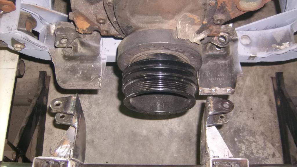
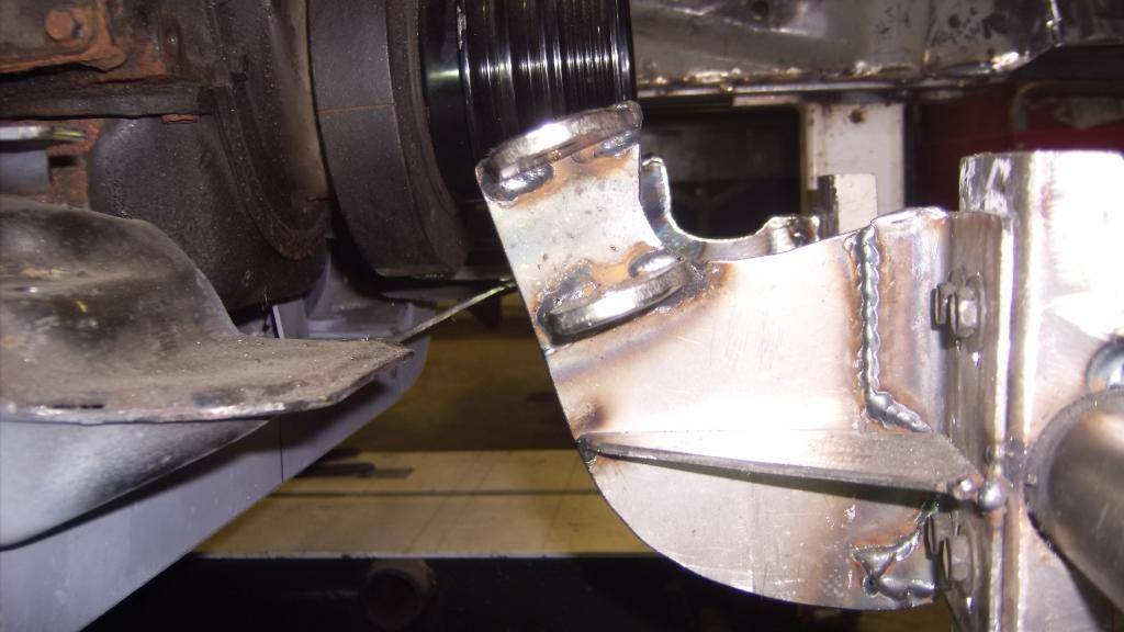
and beginning of metal rack brackets. These were a little more complex as the factory rack mounts from behind but my crossmember is ahead of the rack. Mounts had to come underneath the rack and then up to factory location.
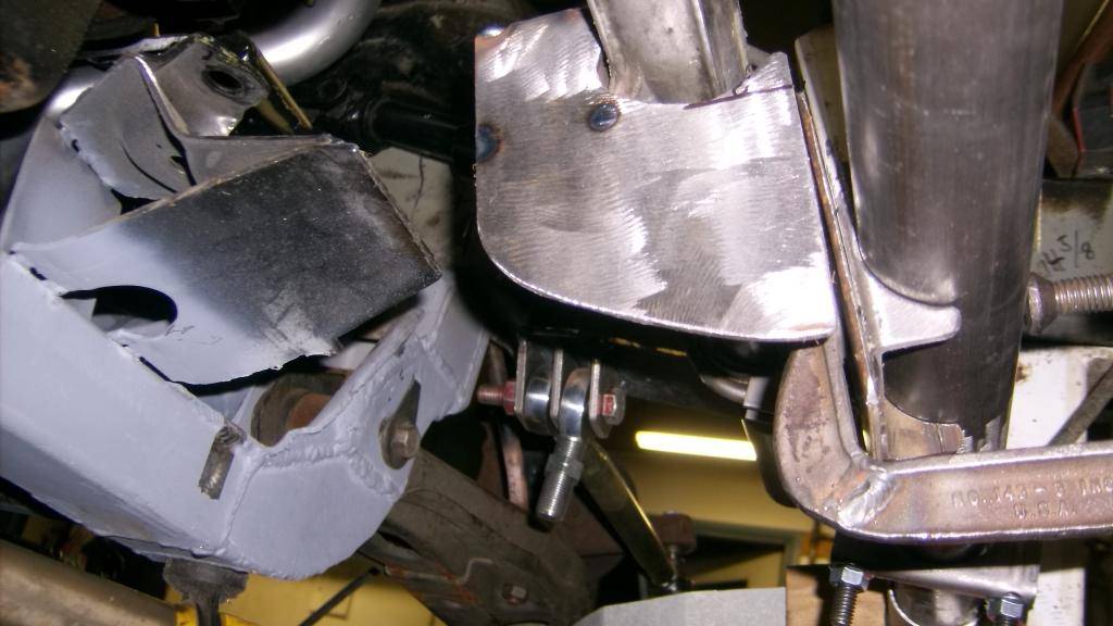
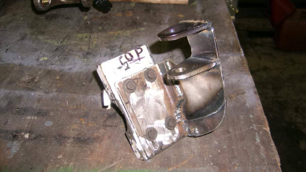
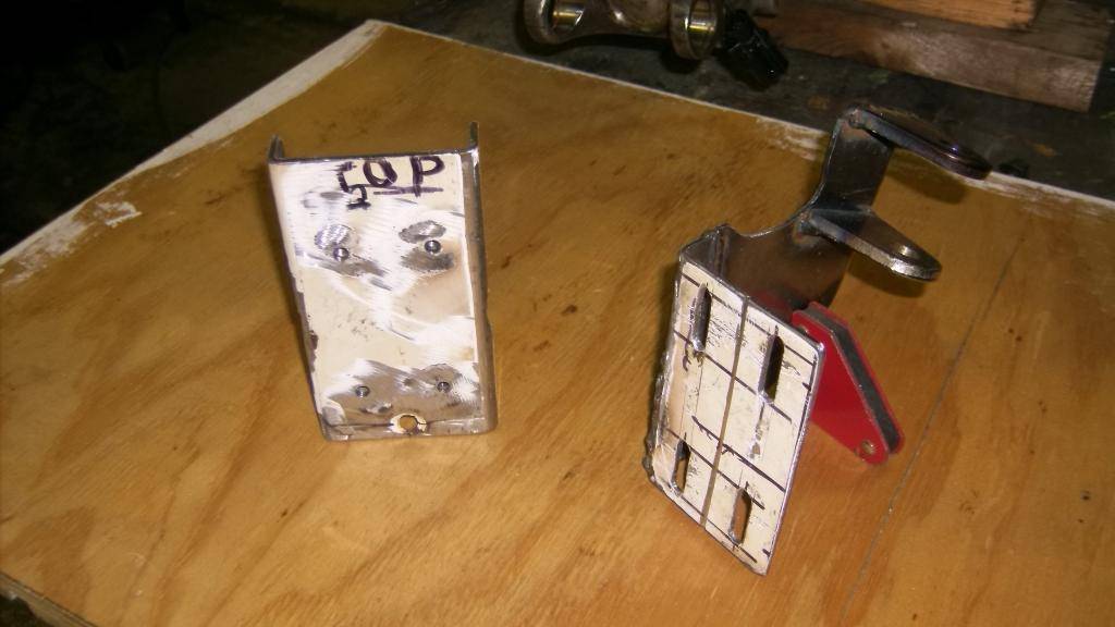
Brackets allow rack to be adjusted up/down 1" for bump steer.
10-10-2015 #39
Registered User
- Join Date
- Jun 2015
- Location
- kent,ohio
- Posts
- 128
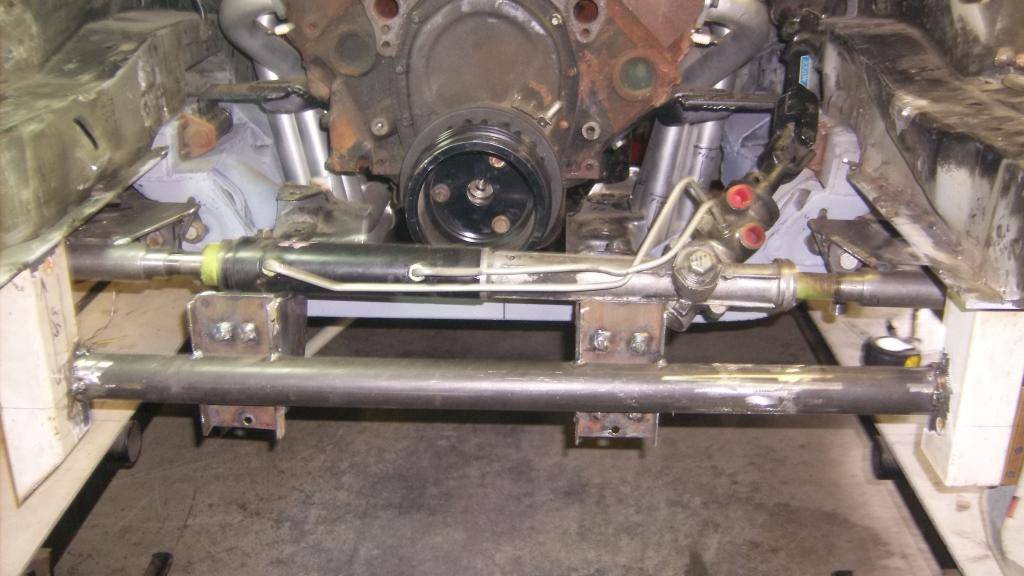
more pics of rack brackets in place.
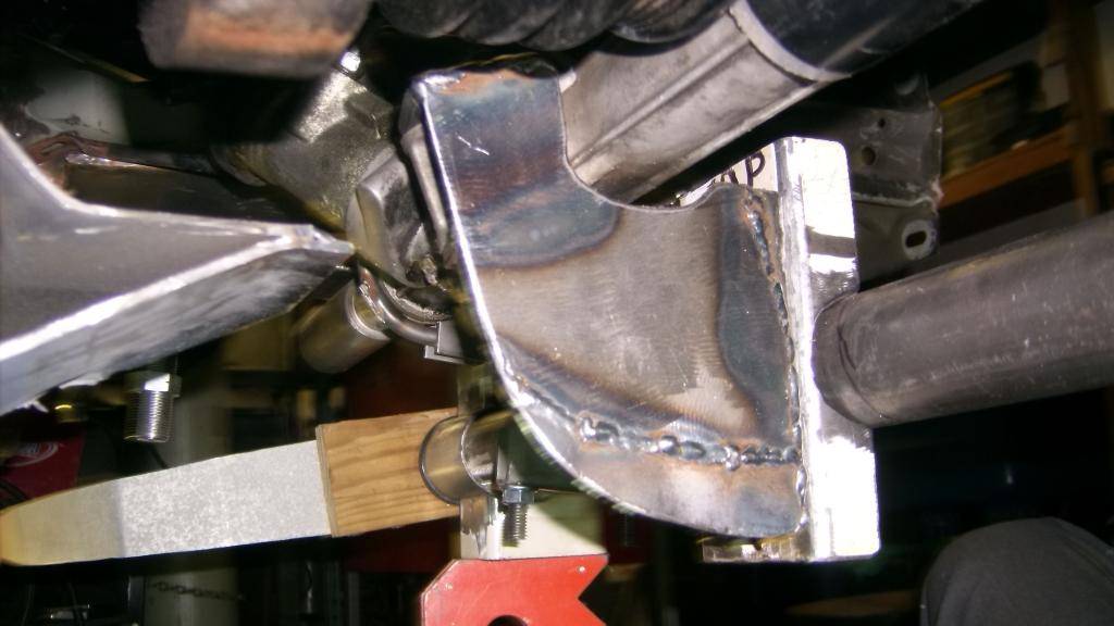
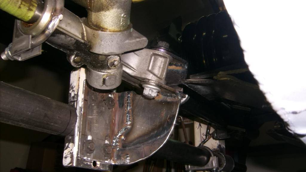
right and left brackets installed
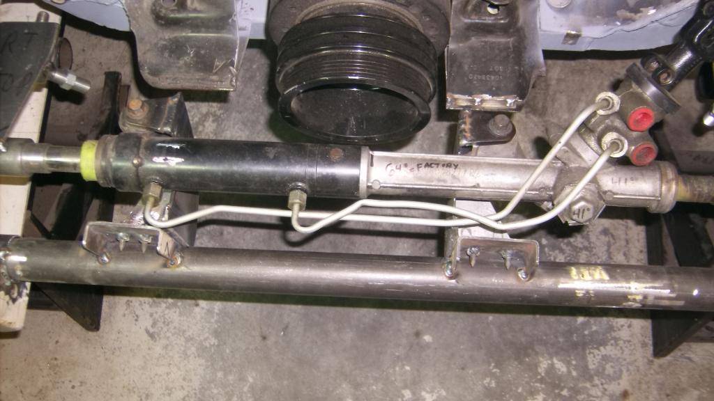
good overhead shot showing rack/pulley clearance.
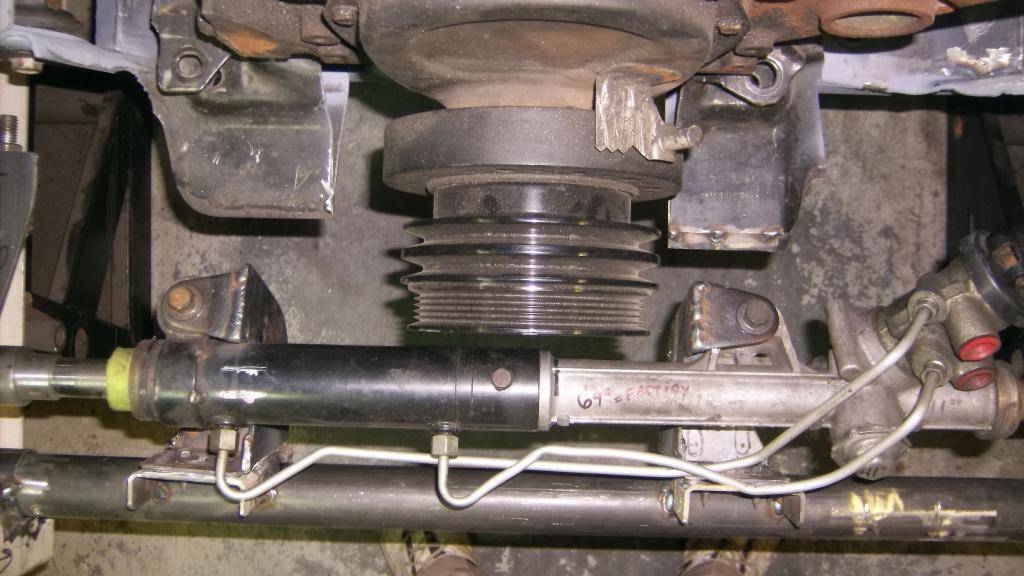
10-10-2015 #40
Registered User
- Join Date
- Jun 2015
- Location
- kent,ohio
- Posts
- 128
because I left the factory rack mounts in place on the new k-member I was able to remount the rack directly forward. You can see in these pics how well the new location lines up with the old mounts, both right to left and height wise as well.
to join the right and left together and help minimize lateral flex I added this brace.
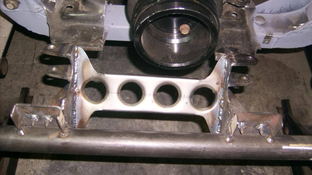
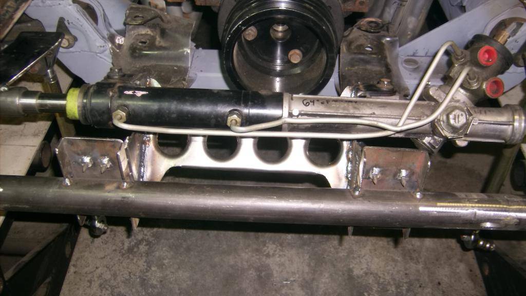
The center brace stiffened the rack mount a lot but I still notice some slight movement of the rack. I made need to remake the whole thing from 3/16 or 1/4 steel plate. The rack is going to be forcing some pretty wide tires to turn a 3000+ pound car into a corner and will have to be mounted solid. I think the design is good, just should have made it from heavier material.


 Reply With Quote





