


Results 41 to 60 of 138
Thread: 3rd gen Z28 track day build
-
10-10-2015 #41
 Registered User
- Join Date
- Jun 2015
- Location
- kent,ohio
- Posts
- 128

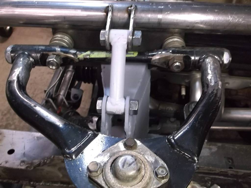
I had originally planned on making the "center link" for this rack conversion out of steel tube and heim joints but while building the rest of the conversion decided a rectangular tube part would work better. 1x2 .125 wall. It bolts to the rack bridge plates with same 1/2-13 gr8 bolt as tie rod heim. I also added a 5/16 bolt from top to hold it in place if just removing tie rod. I am hoping this center link will eliminate any for/aft bending forces ( as viewed from the end) on the rack.
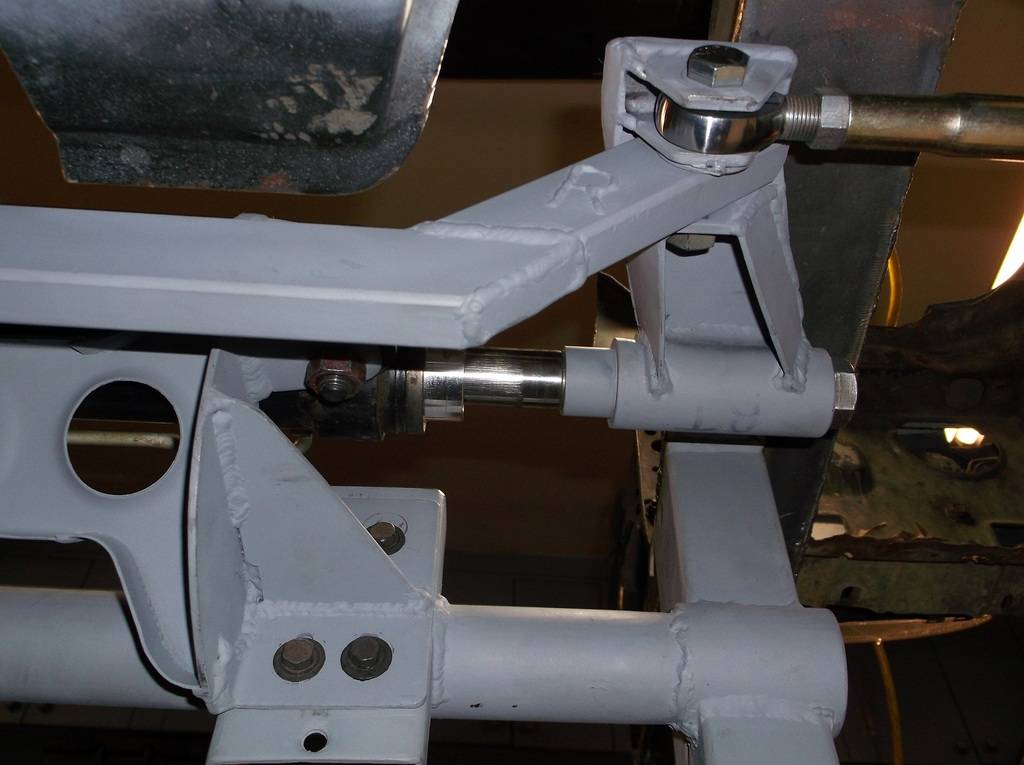
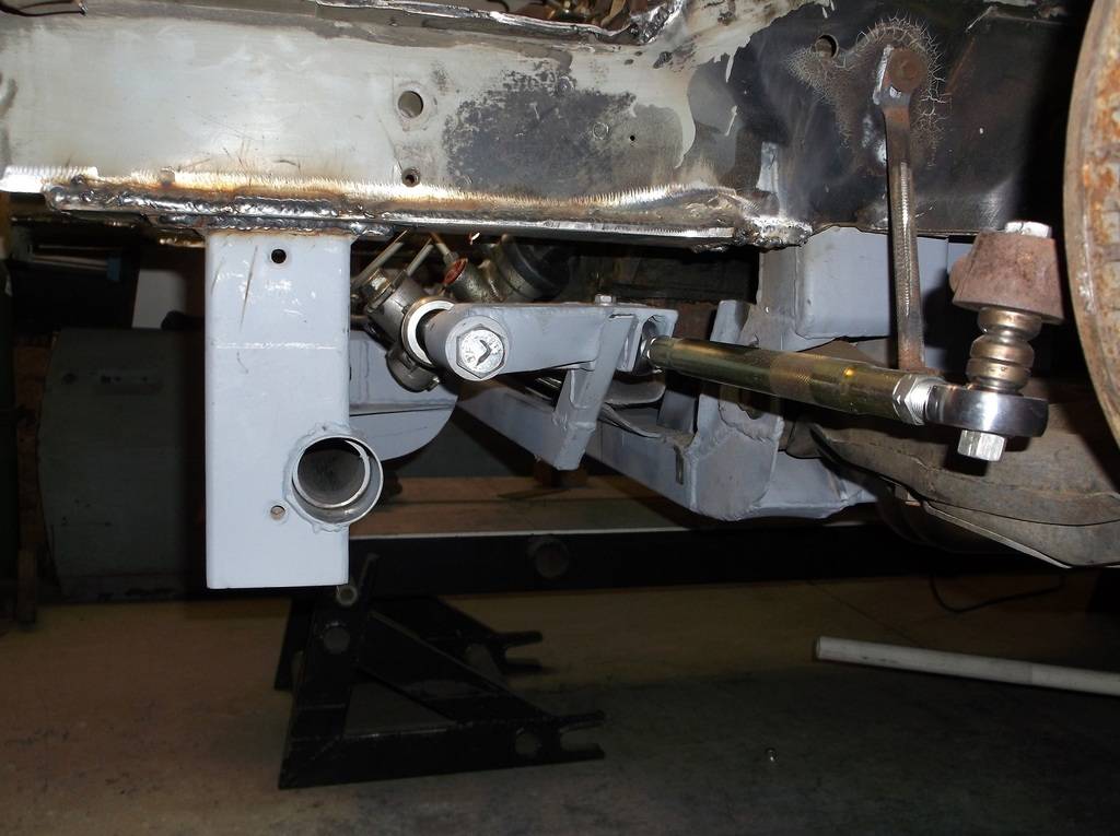
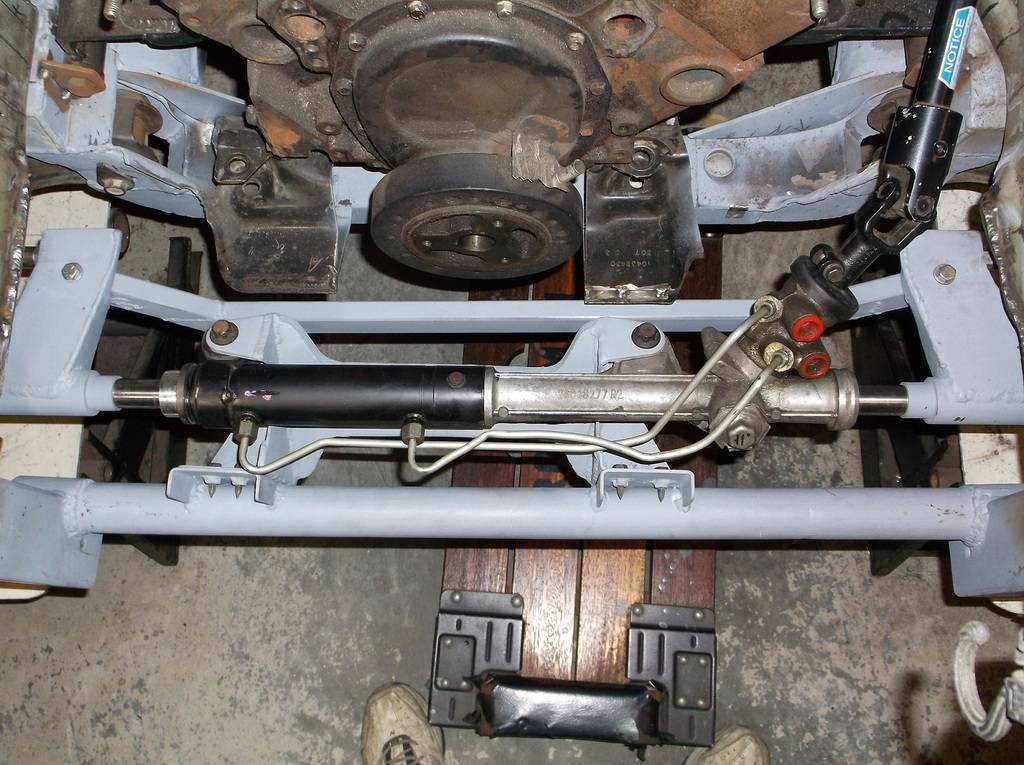
you can also see that I gusseted the bridge plates to strengthen the weld joint at the round rack adapters.
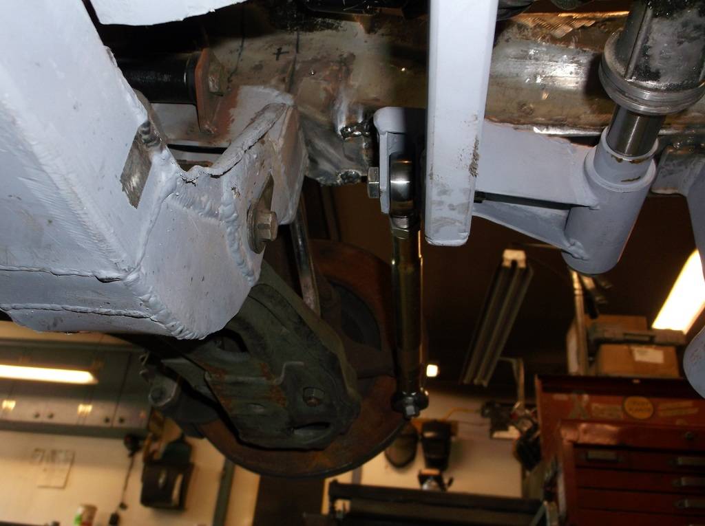
Once the engine instal is finalized I will be making some type of over/under roller support to prevent any up and down forces on the rack due to cornering.
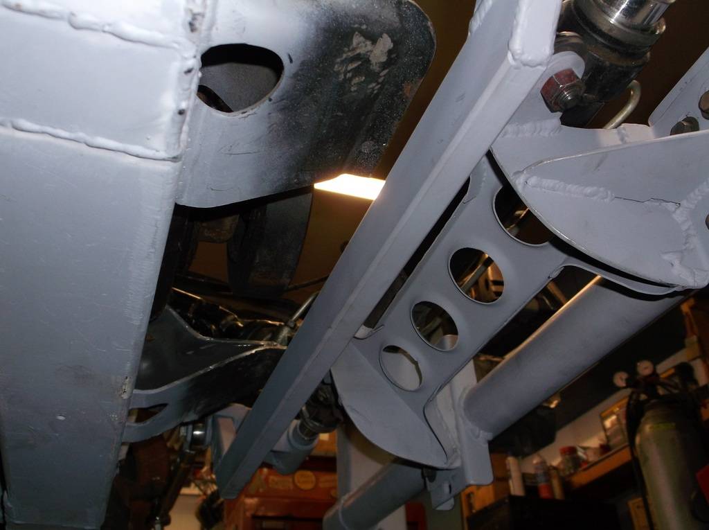
PLEASE, PLEASE, PLEASE, if anyone sees anything or has an idea on how any of this could be done different or safer please feel free to comment. Mounting the rack forward was not something I had planned on and I had to wing it to make the rest of the conversion work. Once the car is back down on its wheels the steering will be looked over carefully and checked for any kind of flexing or binding. The car will be held to light street duty and checked after every outing. Once I feel comfortable that it is indeed safe I'll try a local autox or two and check it some more. Only after it has been thoroughly thrashed at several autox events and has ZERO problems will I feel comfortable to take it on extended highway cruises or track day events.
-
10-10-2015 #42 Registered User
- Join Date
- Feb 2007
- Location
- Tinley Park, IL
- Posts
- 1,217
I am by no means a custom car builder, but I'm thinking all the additional braces, frame rails, connectors, etc... you are adding a significant amount of weight to the vehicle, some of which is up front where you are trying to get rid of it. I'm curious what the car weighs when complete.
I give you a ton a credit for creative problem solving!
Nick ~ 1969 Cutlass
10-22-2015 #43
Registered User
- Join Date
- Jun 2015
- Location
- kent,ohio
- Posts
- 128
Mr Nick thanks for looking in. yeah the steering rack was a head scratcher!!! Something I should have seen coming, but just did not add the rack into my drawings when I was designing the front end. I had the centerline of the rack plotted from a frontal view but not in a top view that would have shown it running through the damper. I really never thought it was a concern as the early 4th gens used the old school SBC with this rack. Originally Posted by Mr Nick

As for the bracing etc, nearly all of it is behind the firewall and except for the roll cage everything is below the floor pan. Ahead of the firewall all of the stock sheetmetal will be removed, fender wells, core support, factory bumper. The only thing remaining is the front frame rails. These will be supported by strut bars that pass through the firewall and tie into the roll cage. I have tried to only add bracing that would help with structural rigidity and safety. The car weighed 320lbs before the build and I am hoping to hold it there or a little less. That is not a bad weight for a streetable PT machine with heat and wipers. I am more concerned with the distribution of the weight rather than the amount.
10-25-2015 #44
Registered User
- Join Date
- Jun 2015
- Location
- kent,ohio
- Posts
- 128
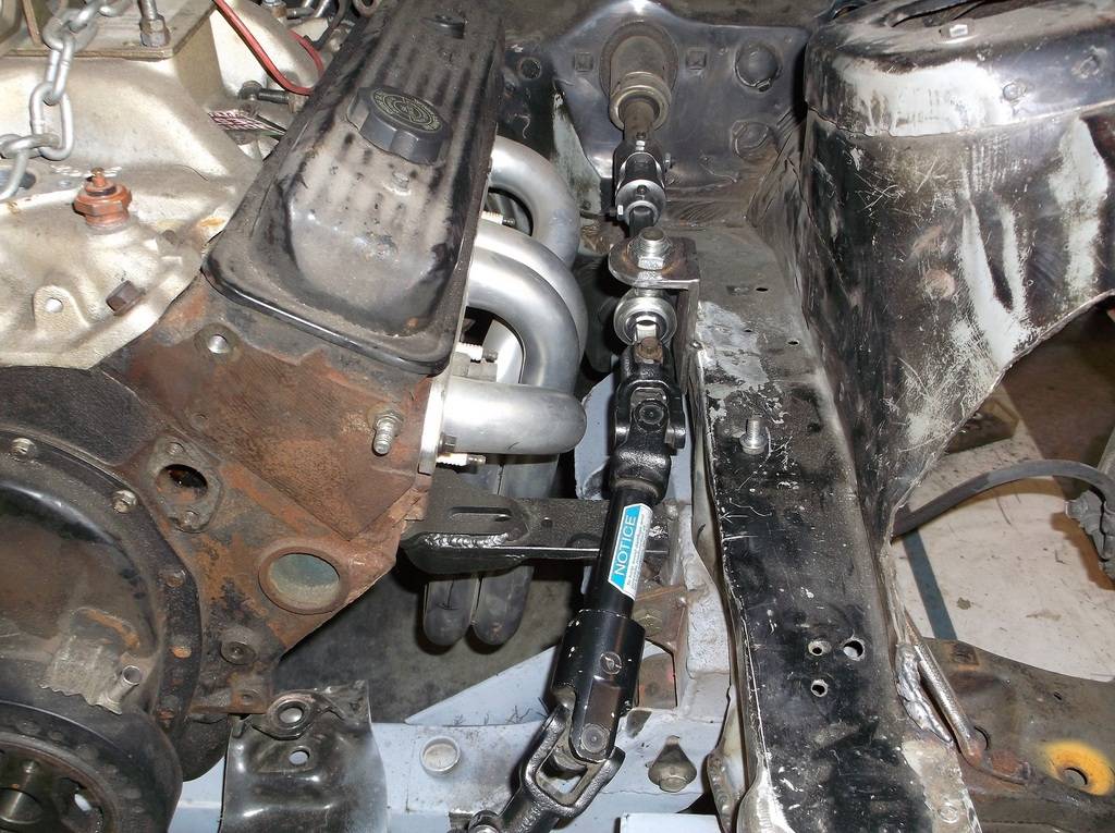
Final steering shaft layout.
Ok I got the k-member, lower control arm and spindle mounted, and the rack issue figured out (I think) so now I had to figure out the upper a-frame and mount. With the tall 4th gen spindle this put the upper ball loint at the top of the OE fenderwell. I have been collecting parts for this build for sometime now, often discounted scratch and dent items from Summit Racing, that I think will work for my build. Many of these parts have nothing to do with 3rd or 4th gen Camaros. I came across these upper control arms, Keiser/Port City stock car pieces for a G-body Monte Carlo. real similar but an 1 1/4 too long.

here is the 4th gen arm mocked int position
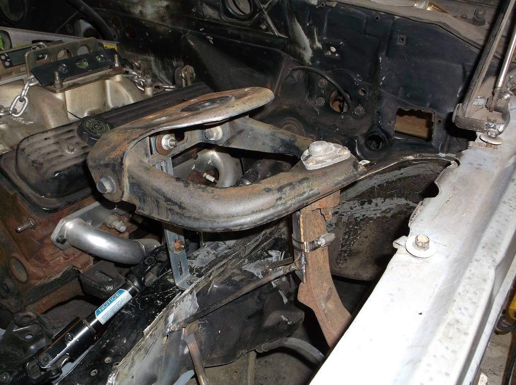
and g-body a-arm
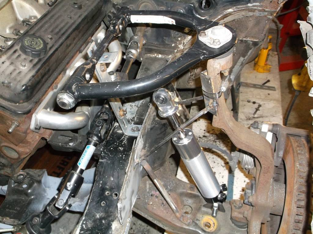
And how it all fits under the hood.
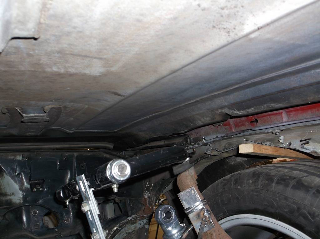
with 3" of up travel I have about 3/4 inch between bal joint and underside of hood
10-25-2015 #45
Registered User
- Join Date
- Jun 2015
- Location
- kent,ohio
- Posts
- 128
I got a 22x17 graph paper tablet and after taping 2 pieces together made a scale drawing of the front suspension to plot the front roll center. I wanted the roll center adjustable from 2 to 4 inches above ground. With the lower a-arm set level at ride height adjusting the roll center height would come by moving the upper a-arm up or down. To get the height of the upper mount I reverse engineered the drawing plotting my roll center first and then the side view instant center and then plotting from their to the upper ball joint. Measuring back the distance from center of ball joint to a-arm pivot gave me my height.
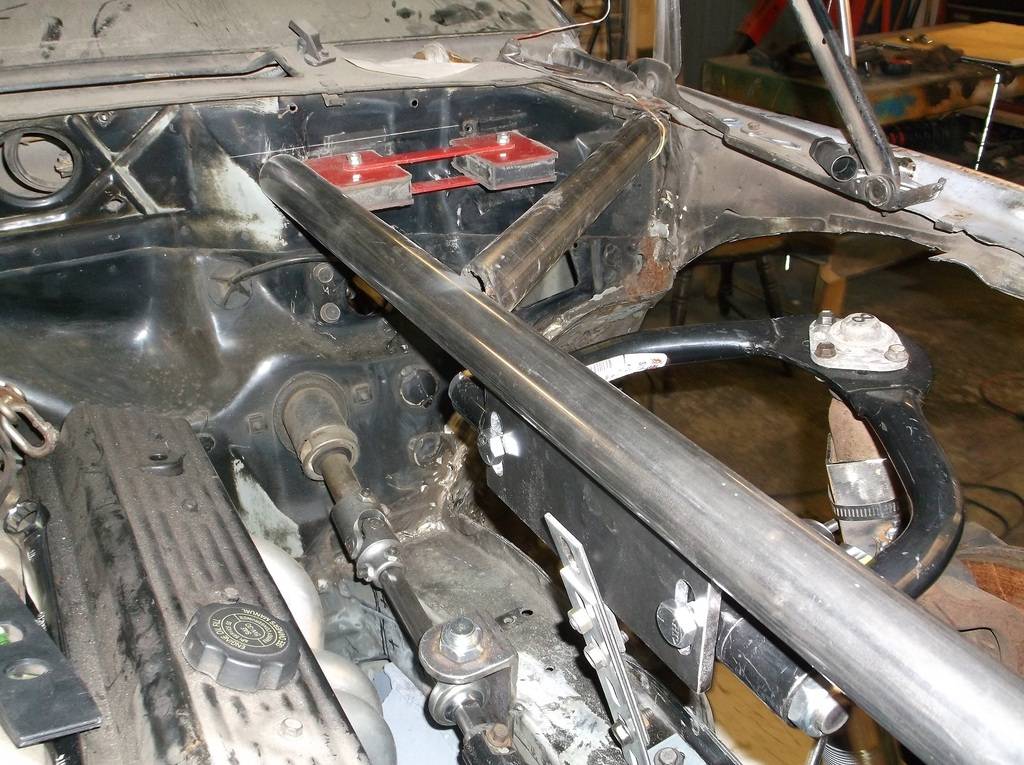
With measurements in hand I spent a few hours figuring out where and how I would locate the upper arm. I wanted it to tie into the front strut bars coming through the firewall from the rollcage. Here is what I came up with.
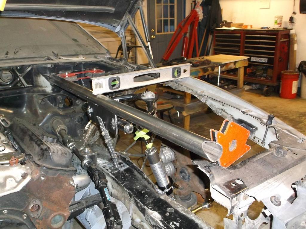
By total coincidence the top of the strut bar is level with the oe frame that ran above the fenderwell.
the scribed line is equal to the top of the knee bar on the roll cage inside.
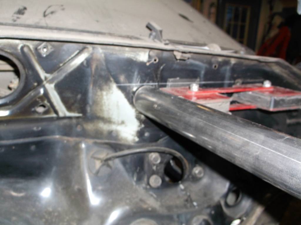
1/4 plate, slotted to give me roll center adjustment and anti dive.

angled tube to outer corner of firewall for lateral support.
10-25-2015 #46
Registered User
- Join Date
- Jun 2015
- Location
- kent,ohio
- Posts
- 128
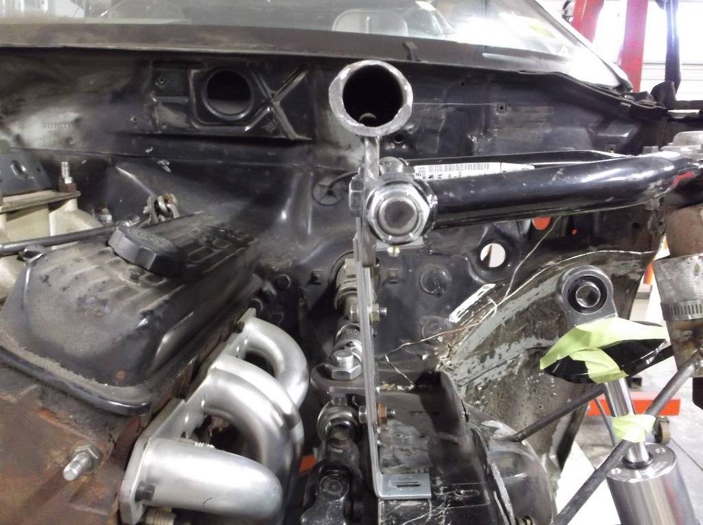
satisfied with the design I cut the holes through the firewall. Cutting thru the backside of the cowl was a bit of a chore but patience and a 12" drill bit exstension got the job done. Everything lined up really well.
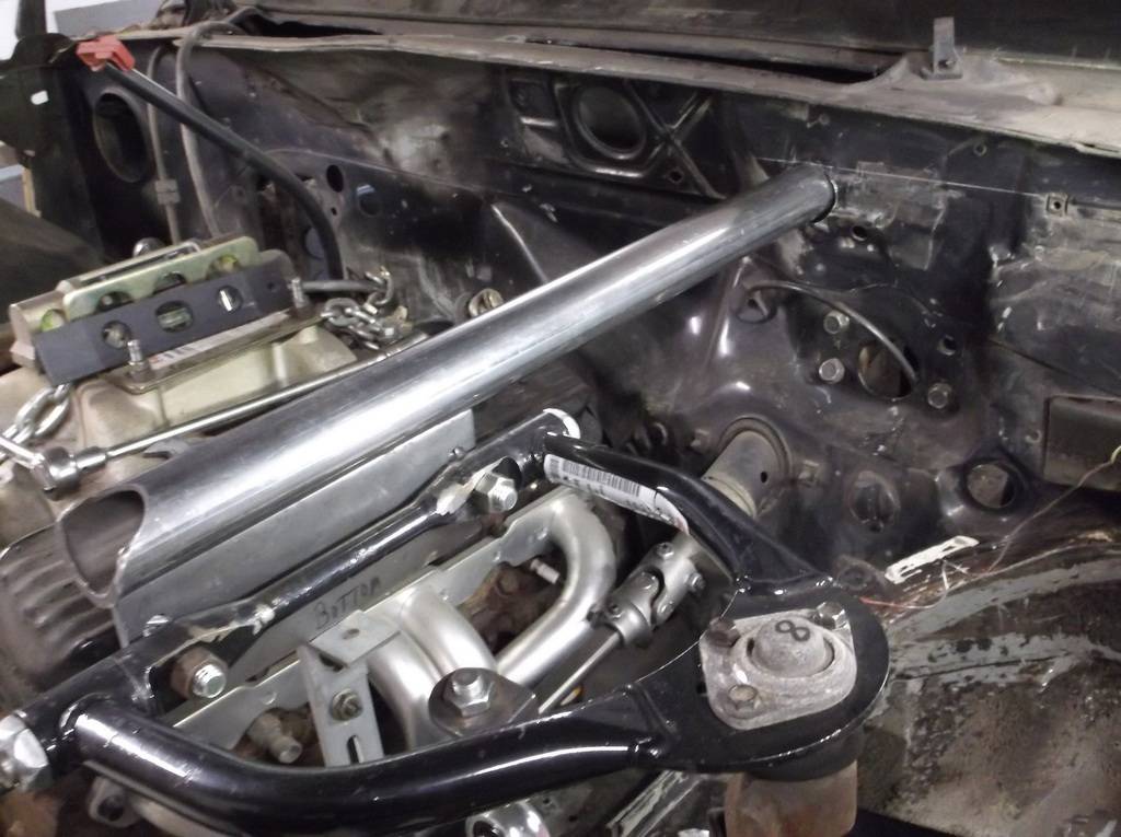
Inside at knee bar
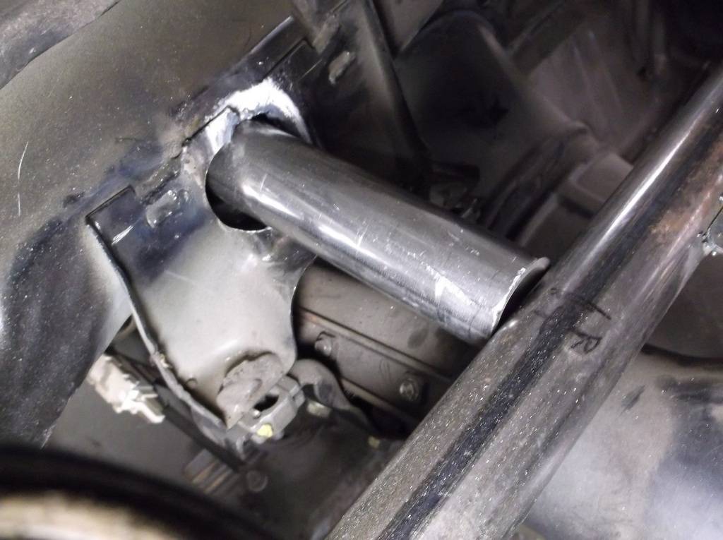
strut tube is dead level

and frontal view
10-25-2015 #47
Registered User
- Join Date
- Jun 2015
- Location
- kent,ohio
- Posts
- 128
I built the cage using the Moroso 10 point kit and ordered the front strut bars to complete the 12 point cage. They were on backorder so after a 2 week wait I ordered the same part from Allstar brand. During the wait I designed the coil over upper mount. this mount will do 3 things, mount the top of the coil over, tie the upper a-arm mount/ top strut tube to the lower frame rail, and provide a link to transfer the force of the spring to a lateral brace that will tie both strut tubes together.
Like this
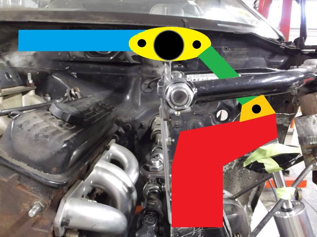
Before I get to carried away I thought I better see if the master cylinder would still fit in the stock location. I am going with manual brakes. A couple of companies make manual brake conversions for these cars usually for drag race applications and they cost $150 or more. They are built around the Wilwood "Mopar" style master cylinder and a CNC'd aluminum adapter plate and an adjustable pushrod. Well for about $40 you can make one yourself. A Dorman mastercylinder for mid 70's Cordoba or 1/2 ton truck, a 4x4 piece of 1/2 thick aluminum and a Tuff Stuff pushrod kit will pretty much duplicate the expensive kits.
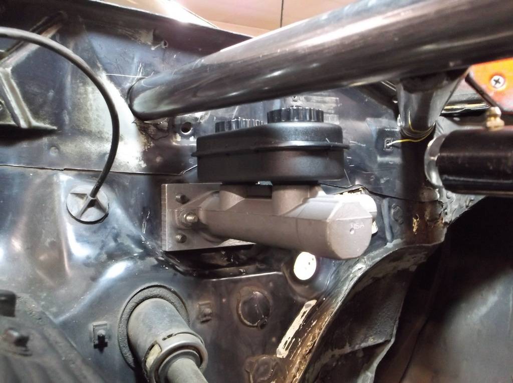
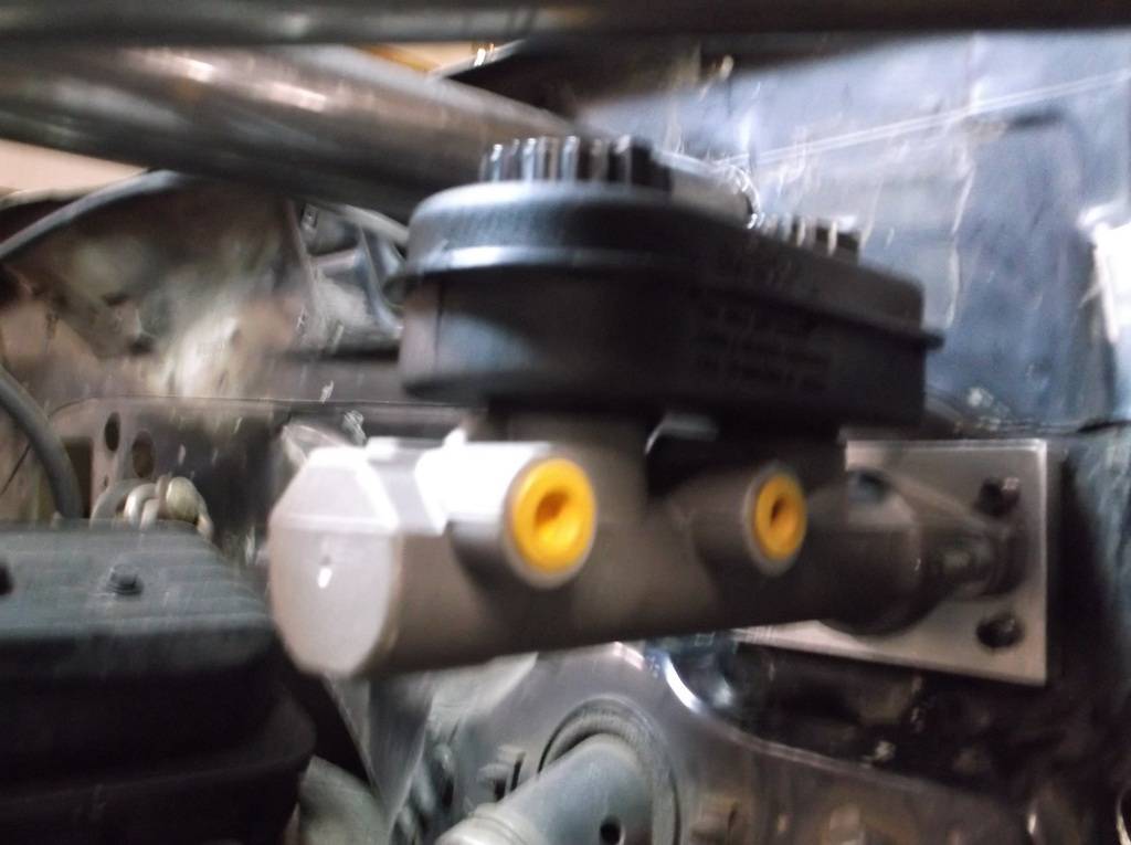
Just clears the strut bar

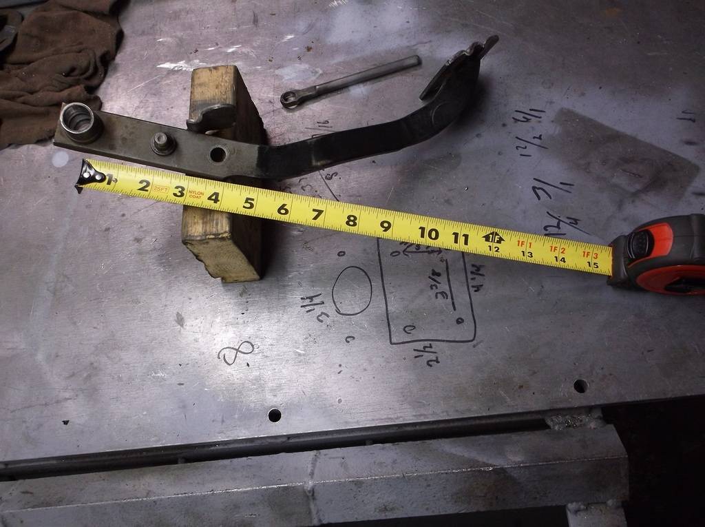
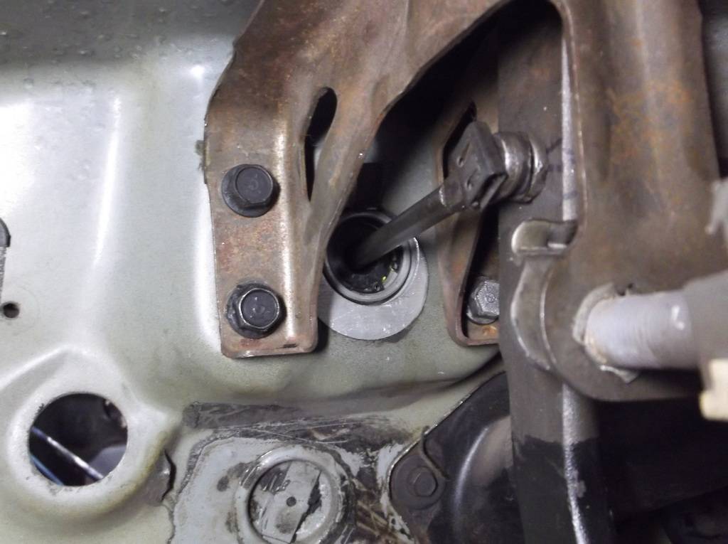
The pedal ratio needs to be changed as well. The stock ratio is about 3:1, fine for power brakes but needs to be double that for manual brakes. This is an easy fix. The brake pedal arm length is about 12" and the factory pushrod pin location is 4" down from the center of the pivot bushing (12/4=3, 3:1). You can grind the small weld off the back and punch out the factory pin. Drill a new hole 2" down from pivot center and weld the pin back in (12/2=6, 6:1).
and it all fits together like this
10-25-2015 #48
Registered User
- Join Date
- Jun 2015
- Location
- kent,ohio
- Posts
- 128
I am a person that believes everything happens for a reason. While waiting for the strut bars to come in I decided I had better see if the coil over springs would clear the frame and spindle. I thought this would be a slam dunk as my coil overs and springs were half the size of the stock 4th gen counterparts. Since I could not compress a 400in/lb spring to ride height length I had to find a way to hold the shock in place at ride height and also simulate the od of the spring. While searching the dark corners of the garage I came across a length of 4" dryer duct tubing.
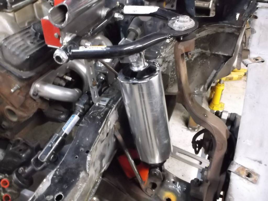
I am sure this is how all of the professional car builders do it!!!!!!!!!
I wanted to get the bottom of the shock as close to the ball joint as possible for better control. The factory location is about center on the length of the lower a-arm and with my smaller package I should be able to move it out farther. Here is where the delay in getting the strut bars turned out to be a blessing in disguise. I had a terrible time trying to move the shock out farther. The more I tried the more frustrated I got. If the humongous factory stuff fit why wouldn't the smaller stuff clear. I could not get the coil over package to clear thru the 5" of total suspension travel (2" down, 3"up). I went back through all of my mounting location measurements again and again, and everything looked ok but something wasn't right. I finally went back and checked my initial spindle location.
I had initially located the spindle with a base alignment of 0 degree camber and +6 degrees of caster, or so I thought. Camber is read directly off of my Rebco bubble gauge but caster requires that you turn the wheel/spindle in and out 20 degrees which I couldn't do. To get around this I used the flat upper edge of the bolt on hub assembly, assuming that when the edge was level there was 0 caster and then tipped the spindle back 6 degrees from level using my Craftsman digital level for measurement.
NEVER, NEVER, EVER ASSUME!!!!!!!!!!!! It turns out that the GM engineers built in about 6 degrees of positive caster into the spindle design so that when the upper edge of the spindle mount was level the actual caster reading would be 6 degrees positive. With the upper a-arm mocked up and tack welded into place I could now turn the spindle in and out and my ASSUMED 6 degree caster setting was actually 12 degrees. To get it set back to 6 degrees I had to cut the upper a-arm mounting plate loose from the strut bar and move it almost 2" forward. This moved the top of the spindle forward 2" and dropped the steering arm about about 1/2". After all this the shock magically fell into place, though I had to mount the bottom of the shock in near the stock location.
edge of bearing cassette that I used for caster measurement. When level, caster is actually about 6 degrees positive.

original position of upper mount on strut tube
upper mount repositioned after caster correction.

if the strut bars had not been delayed I would have welded everything together and ruined the whole build. Somebody was looking out for me big time.
11-07-2015 #49
Registered User
- Join Date
- Jun 2015
- Location
- kent,ohio
- Posts
- 128
I mentioned earlier that the upper a-arms were about 1" too long. I left them long while I positioned the upper mount at a baseline 0 degree camber. Now I shortened the a-arms to the 7 1/4" 4th gen length and it made room for about a 1" shim pack that will allow me to adjust caster and camber at the upper control arm.
Marked arms with 1" masking tape for cut lines.
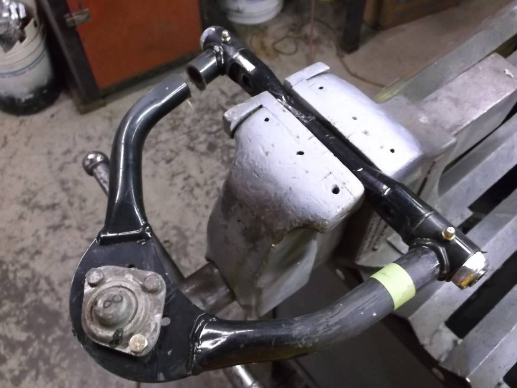
after cuts

tubing to reinforce weld joint
plug welds

fully welded and smoothed.
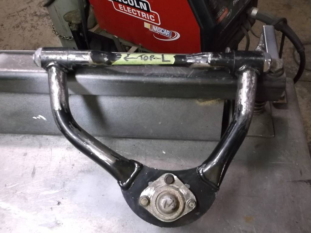
reinstalled with adjusting shims (washers)
11-07-2015 #50
Registered User
- Join Date
- Jun 2015
- Location
- kent,ohio
- Posts
- 128
Next project was to make the upper shock mount. This had to be strong enough to handle the spring forces of the coilovers and I wanted it to tie the upper strut bar to the lower frame rail. A little head scratching, some sketches and a couple cardboard templates and this is what I came up with.
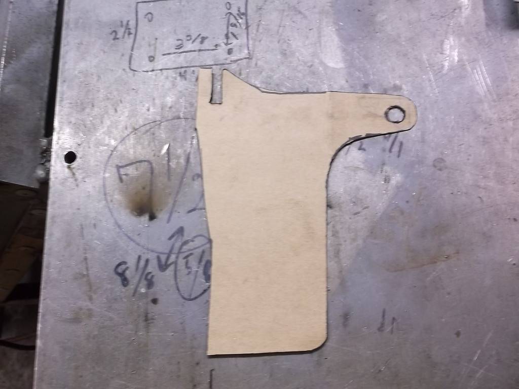
The part is almost 9" high by 7" wide and made from 1/8 steel sheet. The larges pieces of steel that I had were only 6x6, so in keeping with the low budget theme I welded 2 pieces together.
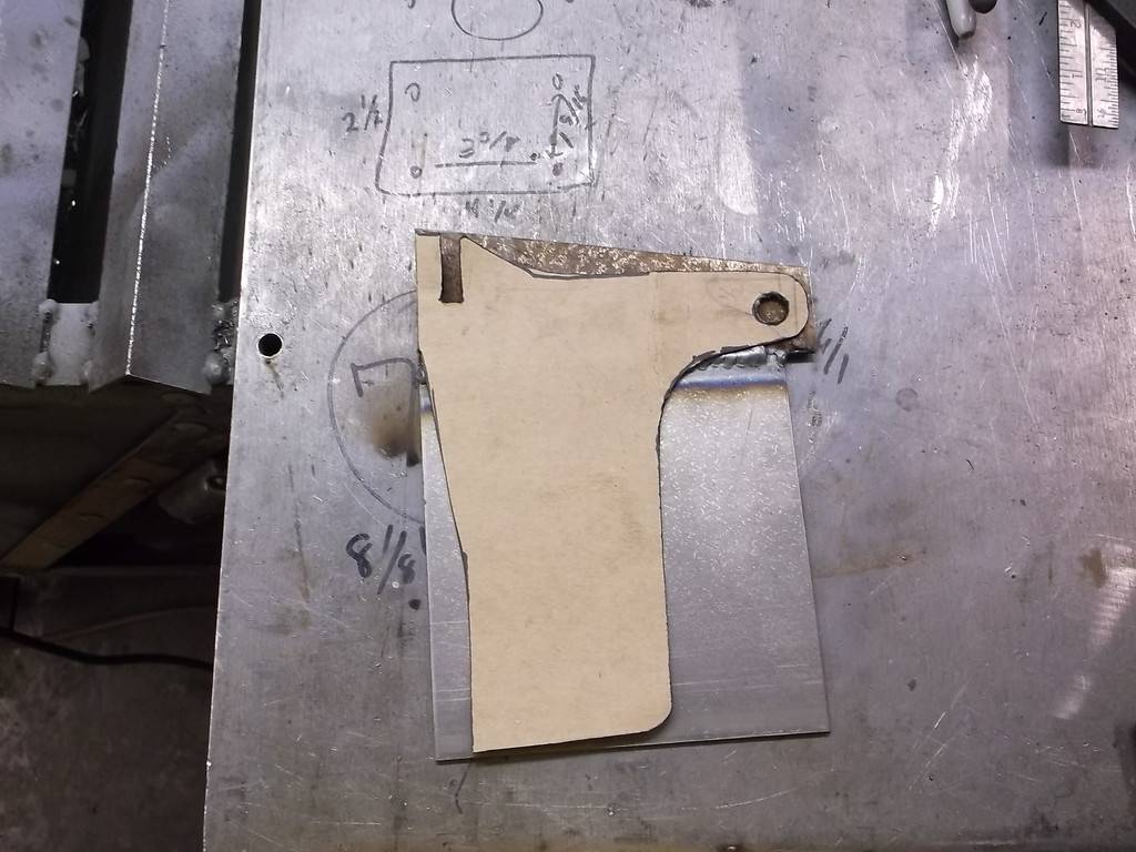
two pieces per side
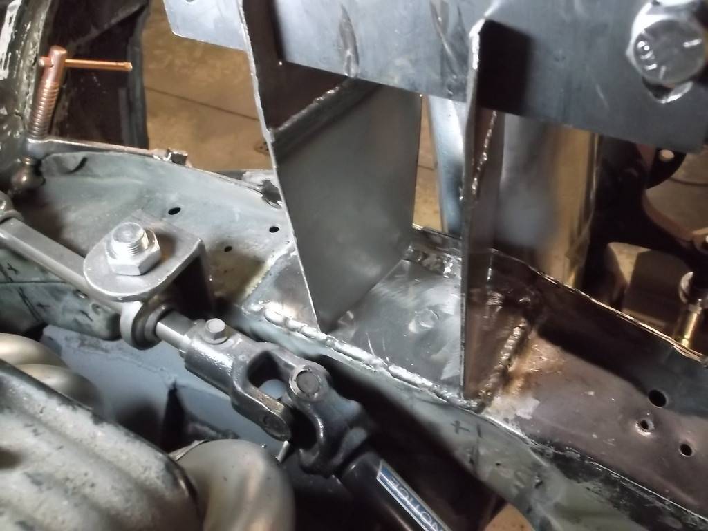

The link between the shock and the strut bar helps spread the spring load.
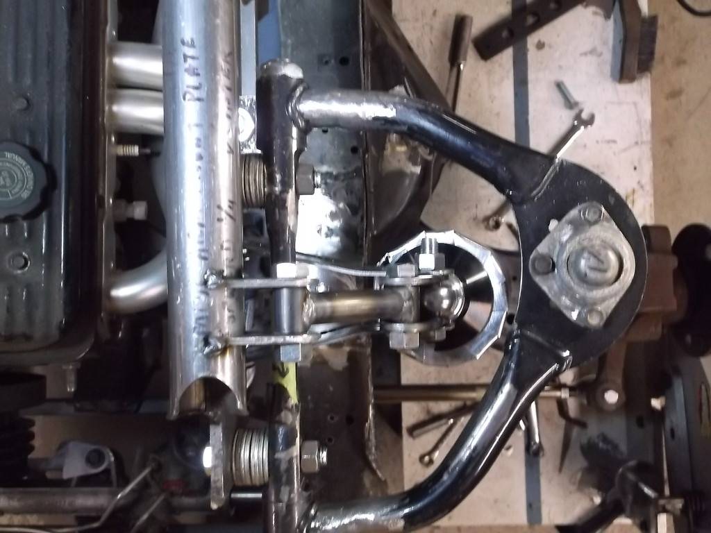
the front strut bars finally showed up. they are about 60" long and I cut them down to 55". This put the front of the bar atop the sway bar mounts.
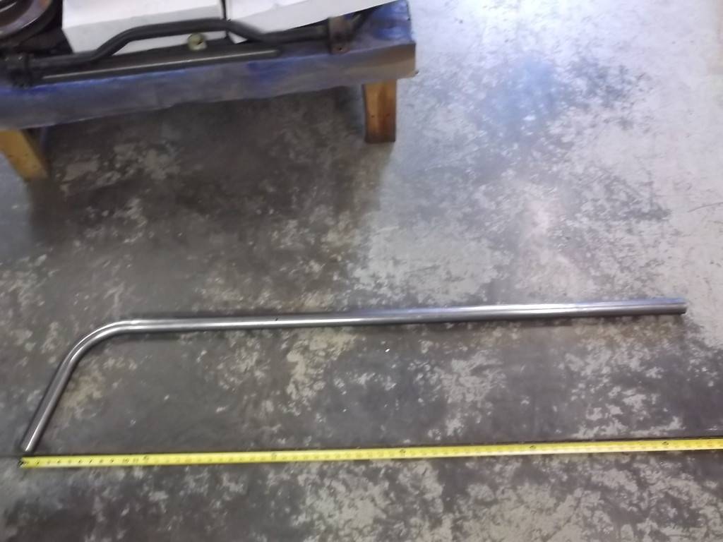
notching the strut bar to fit the knee bar behind the dash was easy enough but the front of the bar was a bit more difficult.
strut bar at knee bar
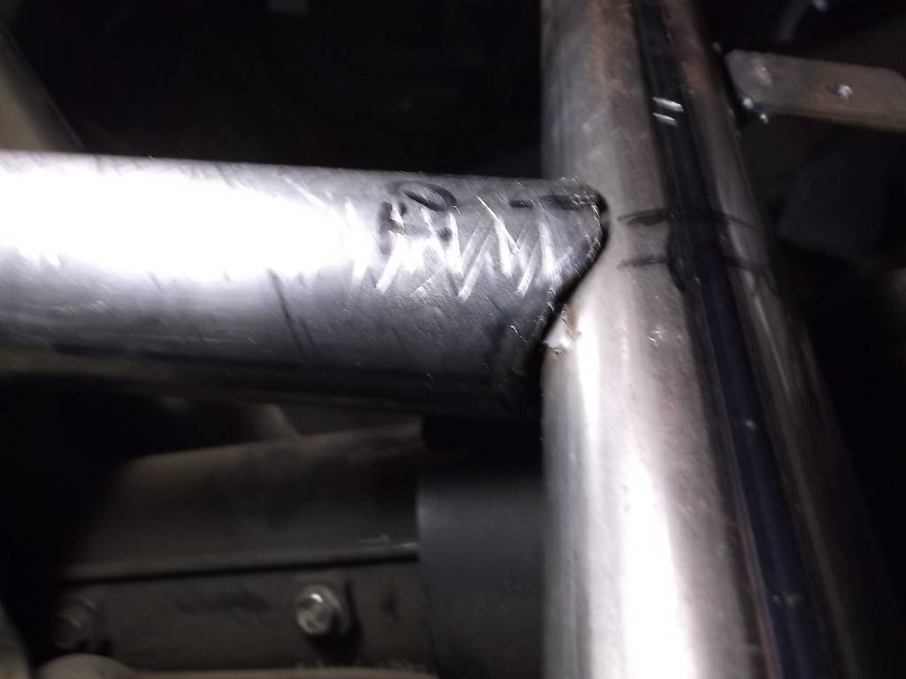
The bar angles down at a 25* angle and had to also angle slightly to the outside to set over the lower frame rail. The lower frame rail angles down towards the front and also angles up toward the outside. After a couple of tries to fit the tube to the frame rail I decided to use a loose fitting collar that I could fit to both the tube and the frame.
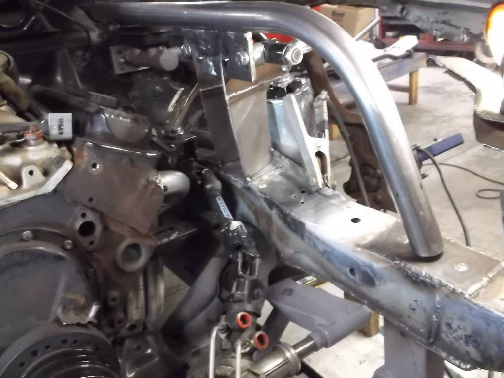
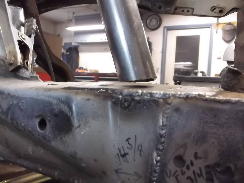
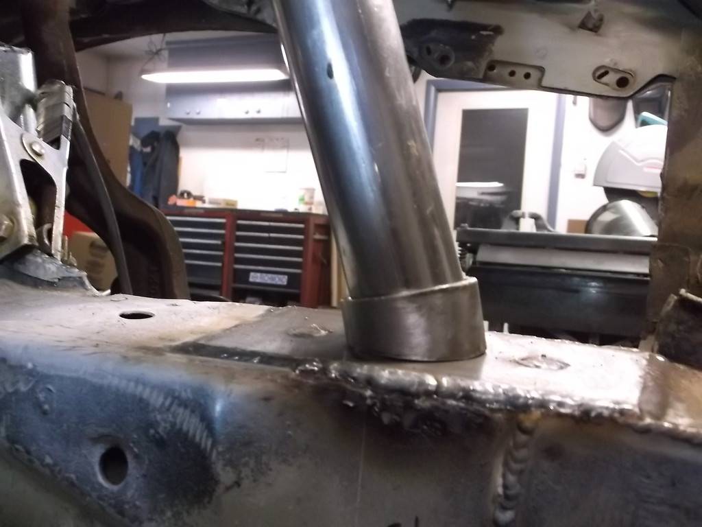
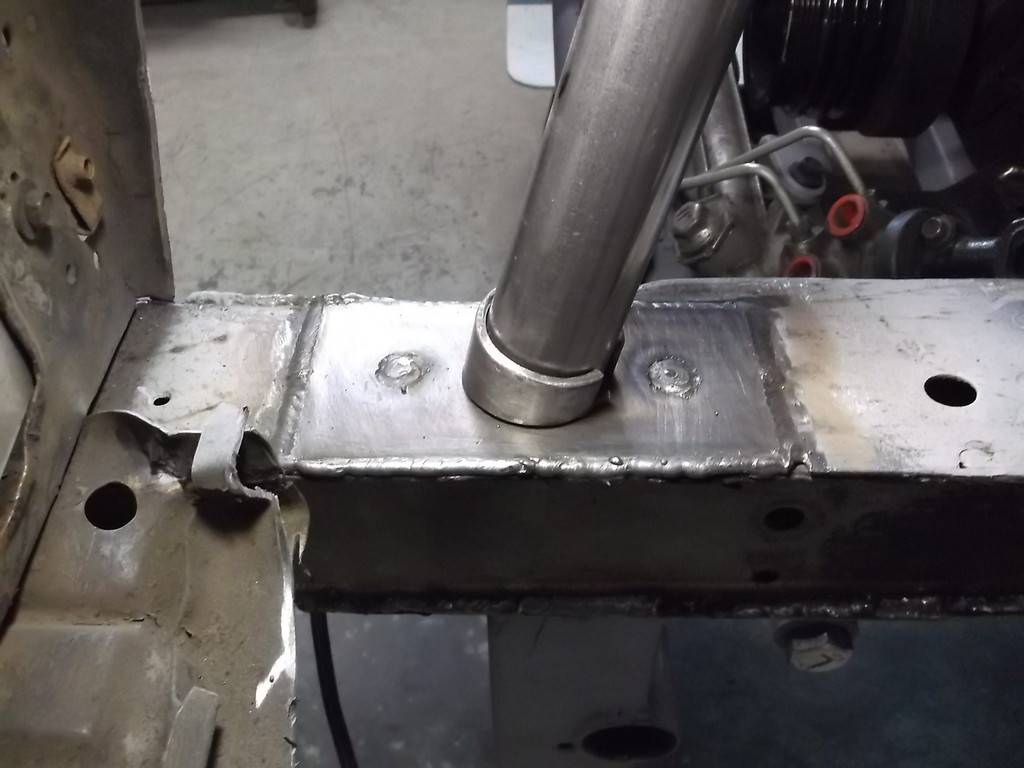
Now I have a reasonably close fit of both parts that will make for a stronger weld joint.
11-07-2015 #51
Registered User
- Join Date
- Jun 2015
- Location
- kent,ohio
- Posts
- 128
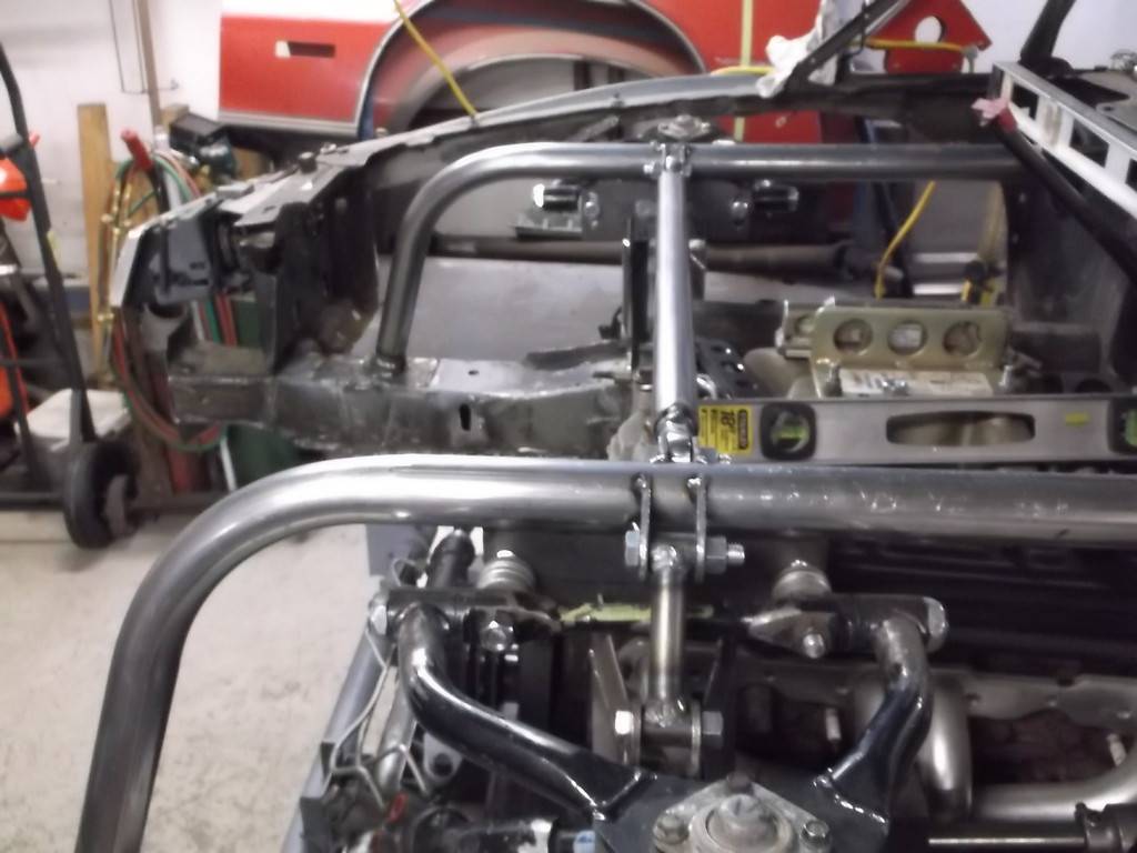
here is a good pic of how the strut bar and shock mount all tie together. This view is with the suspension at 3" compression (up travel). The top of the ball joint clears the underside of the hood by about 3/4".
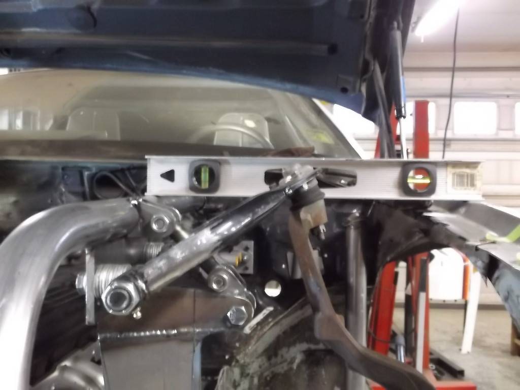
another view.

Same setup was used on the right side of car as well. I was able to keep R and L strut bars nearly perfectly level.
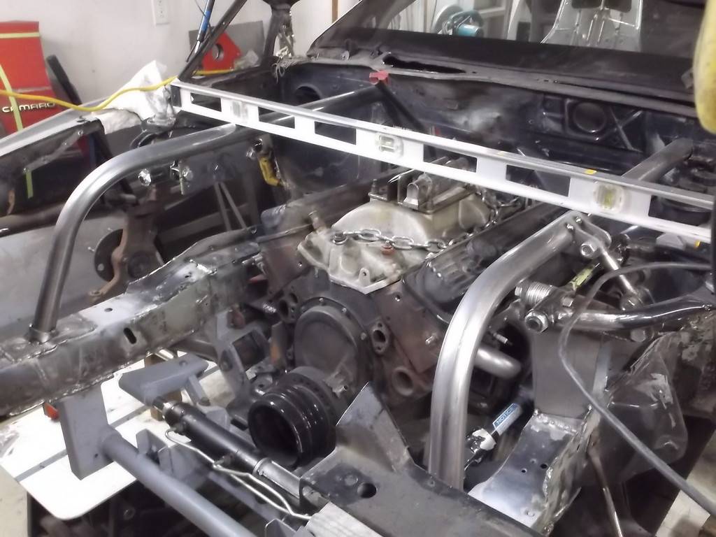
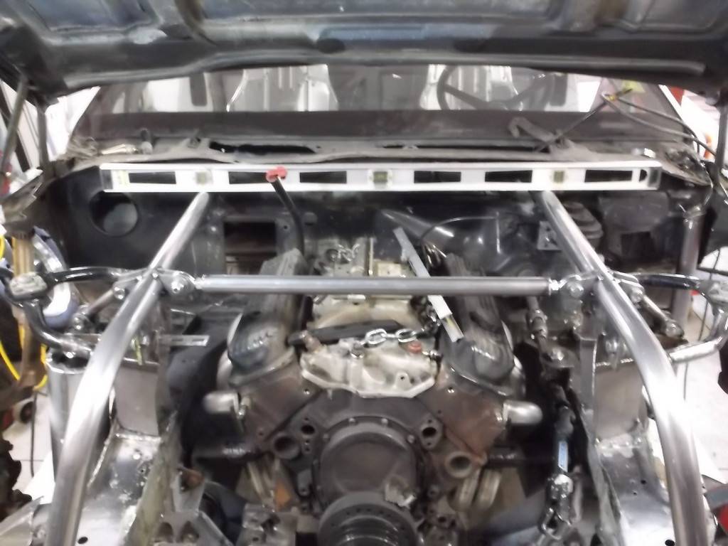
Got an Idea for cross bracing the front of strut bars.

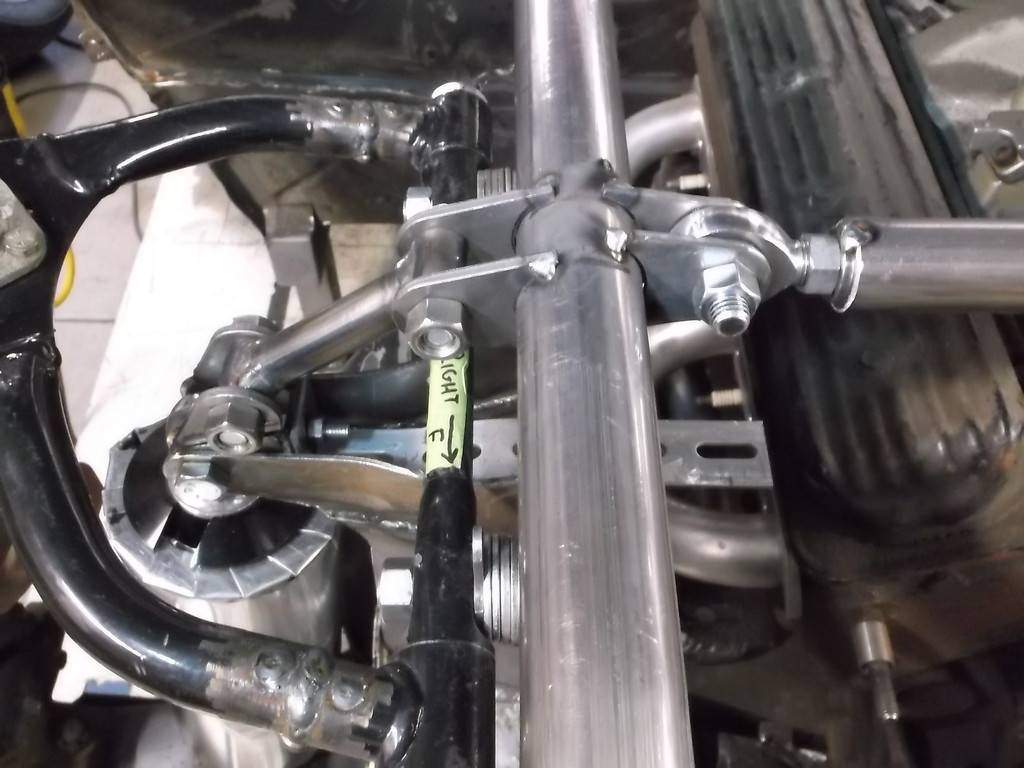
Added a lateral link to tie both strut bars together. this should help transfer the forces from the front springs.
11-07-2015 #52
Registered User
- Join Date
- Jun 2015
- Location
- kent,ohio
- Posts
- 128
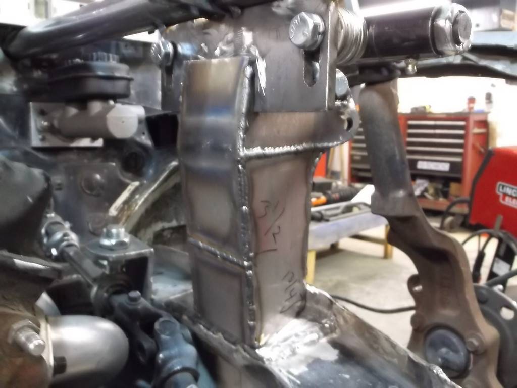
boxed in the shock mounts.
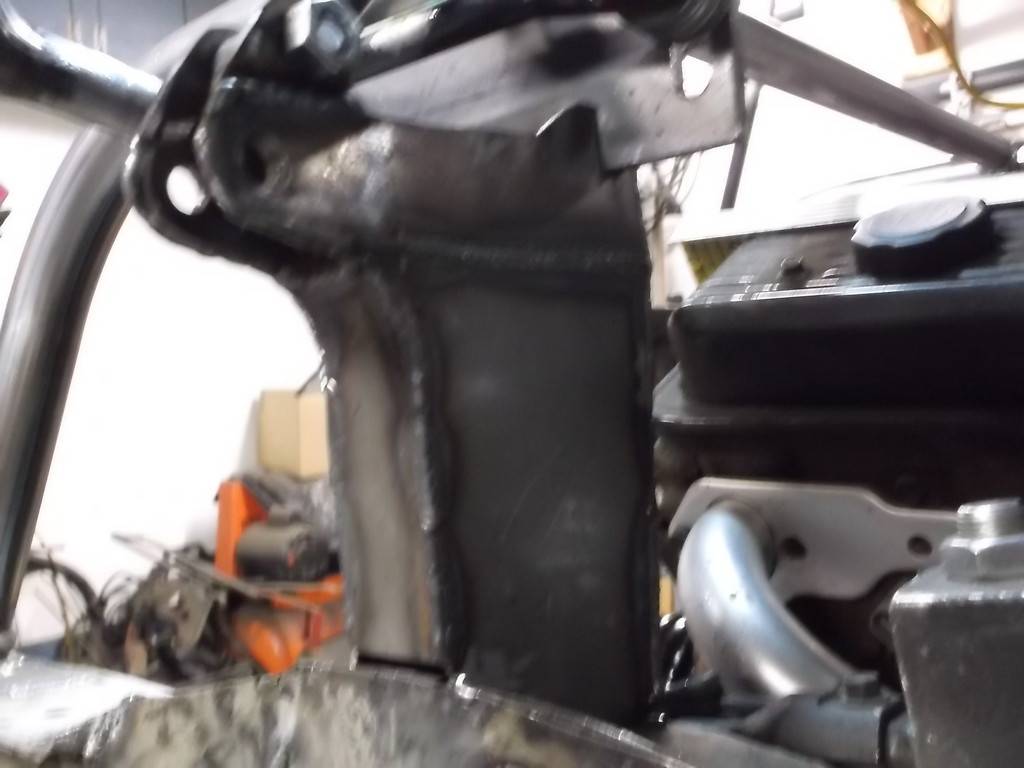
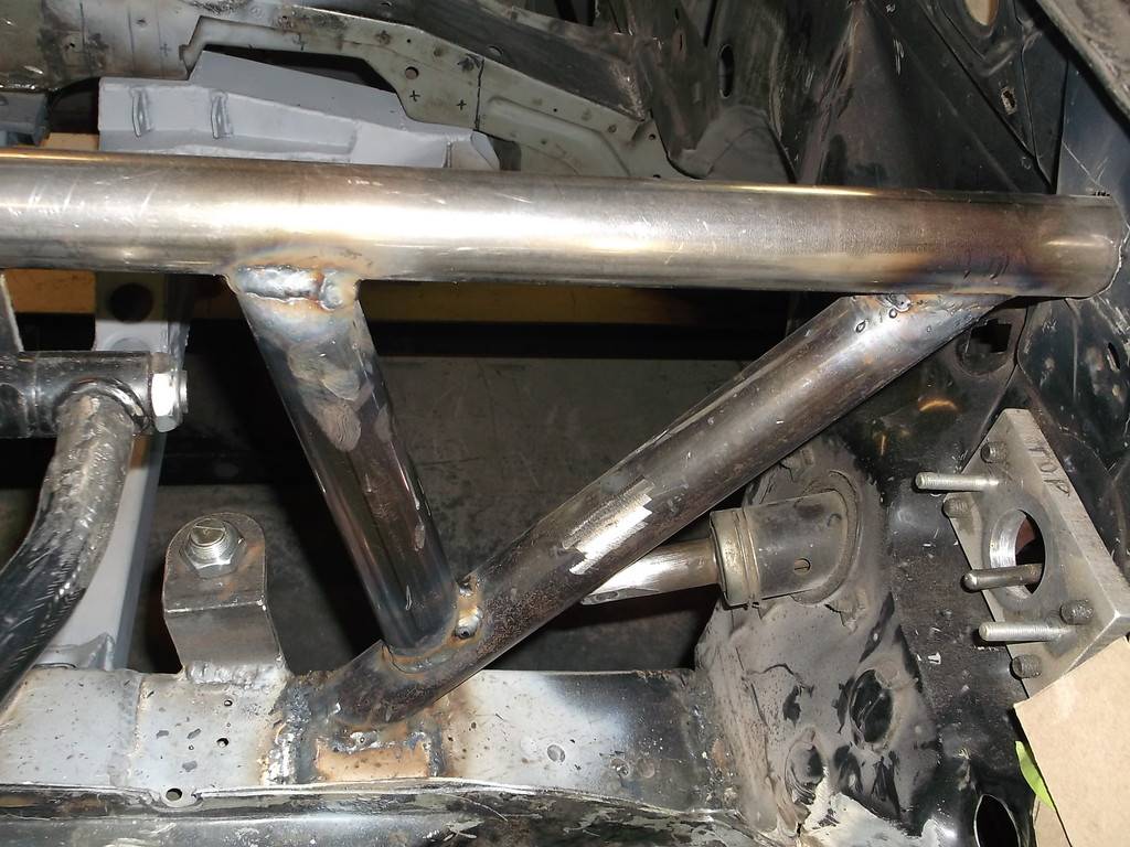
Triangulation of strut bars to frame rail.
concept

actual layout
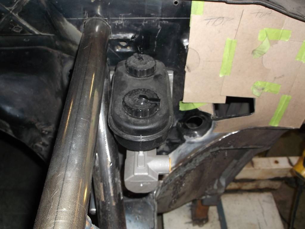
Master cylinder clears by 1/8".
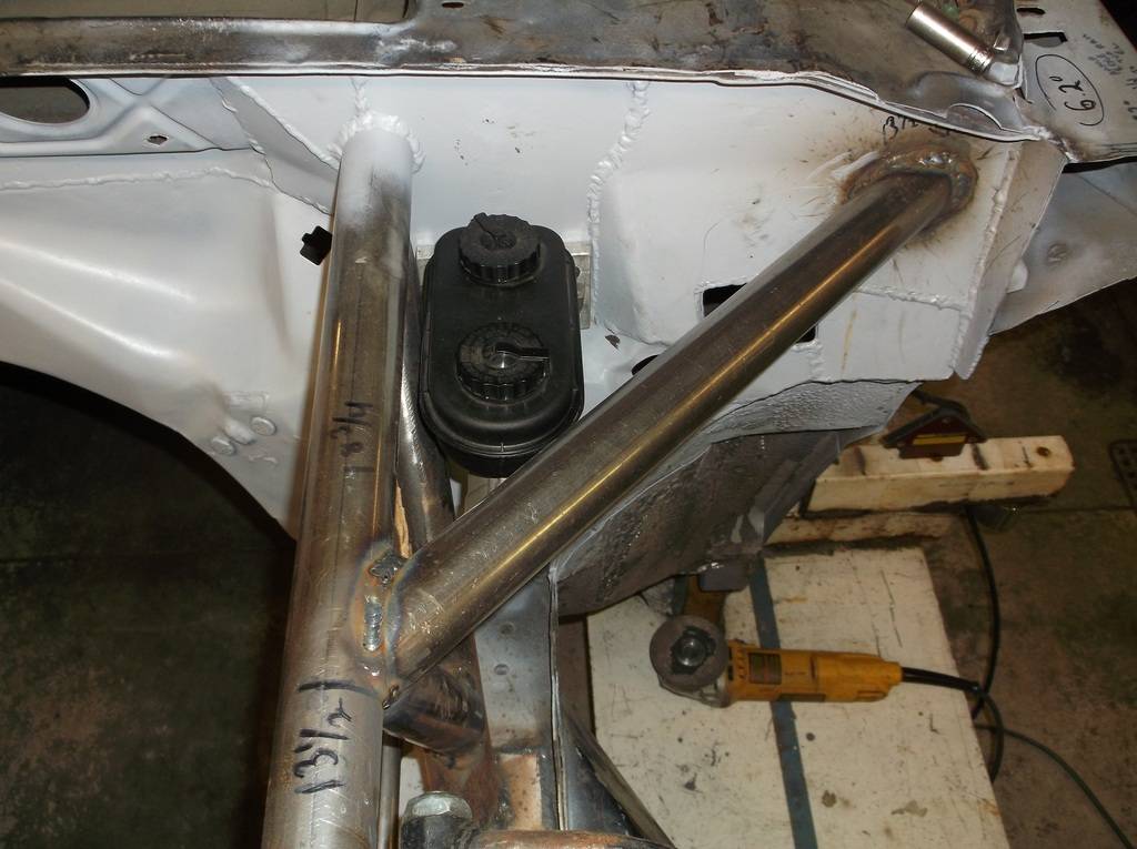
I wanted to triangulate the top of the strut bars by adding a short length of tubing from just behind the upper A-arm mount to the upper corner of the firewall.
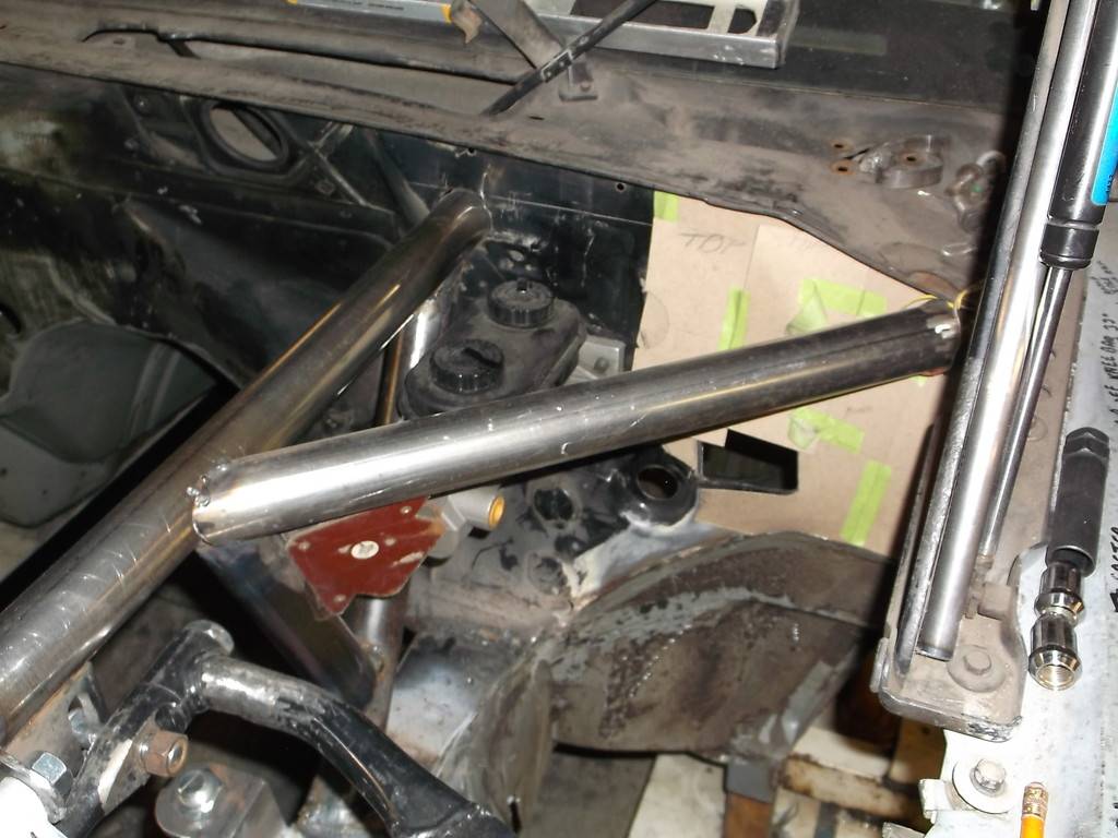
The firewall is made from 20ga sheet steel and is pretty flimsy. I had to reinforce the top half with 1/8" sheet steel and finished the the heater delete bottom half with 18ga.
templates
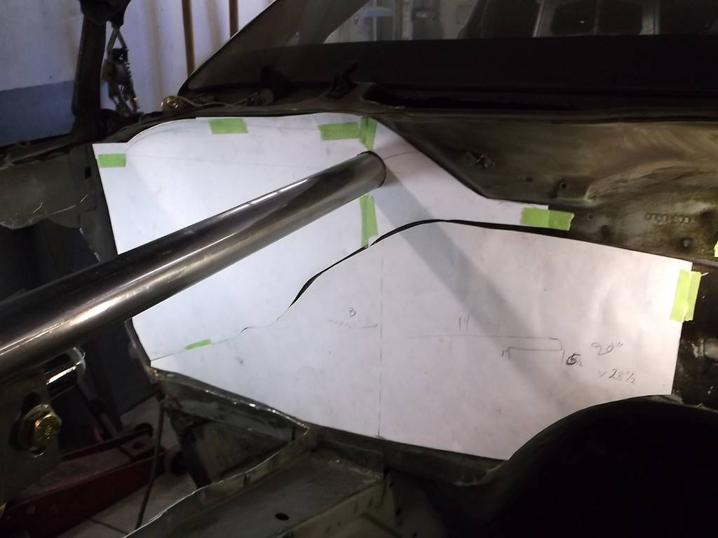
In steel
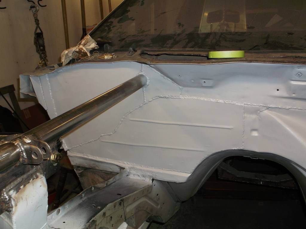
driver's side

and bracing in place. Front end should be very stiff.


11-17-2015 #53
Registered User
- Join Date
- Jun 2015
- Location
- kent,ohio
- Posts
- 128
I am running a TKO 600 trans with a Mcleod universal hydraulic t/o bearing kit. I figured its time to hang the clutch pedal and master cylinder. i wanted to place it between the brake m/c and the engine wire harness opening but realized there was not quite enough room. Solution was to move the wire harness hole over 1". I cut the opening out larger and then welded in a filler piece.
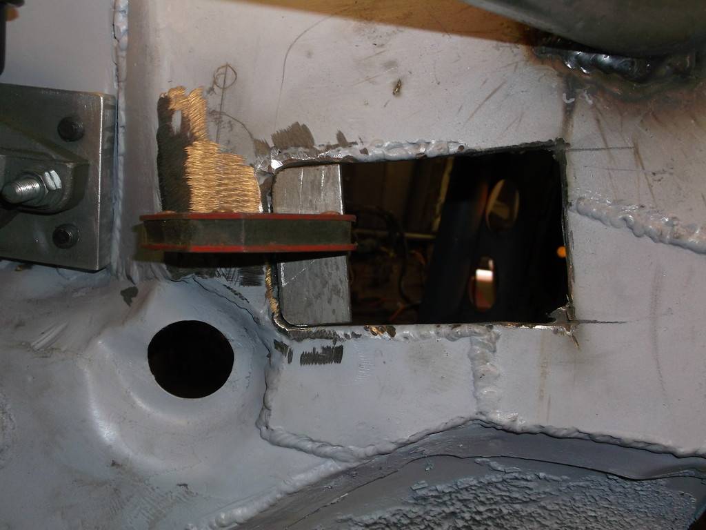
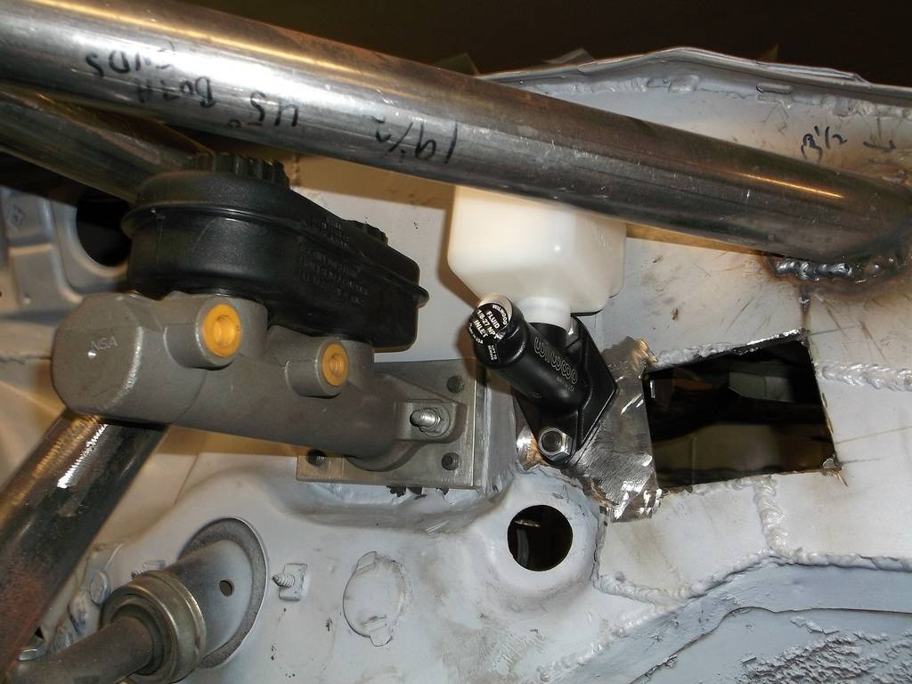
master cylinder mounted.
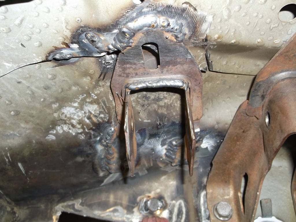
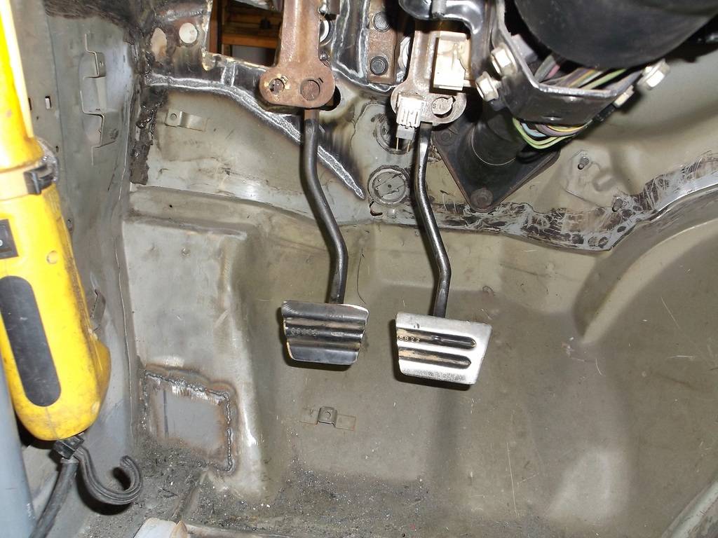
Since I wasn't using the oem clutch hydraulics the factory pedal and bracket didn't align very well i ended up reworking another oe brake pedal and bracket. Bracket was welded to under side of cowl.
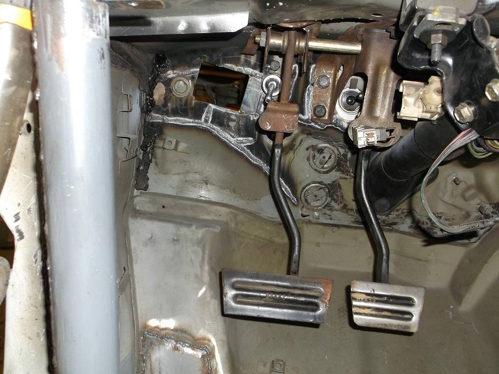
of course the brake pedal had to be cut down. I kind of like the symmetry.
11-17-2015 #54
Registered User
- Join Date
- Jun 2015
- Location
- kent,ohio
- Posts
- 128
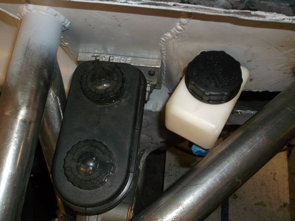
The clutch master cylinder didn't quite lay flat against the firewall and I was afraid to tighten it down and break off a mounting ear. It only took a simple flat washer to fix it but it leaned the m/c just far enough forward that it hit the diagonal brace tubing. The reservoir swivels so no big deal but now it looks sloppy. maybe I'll notch the tube.
before shimming
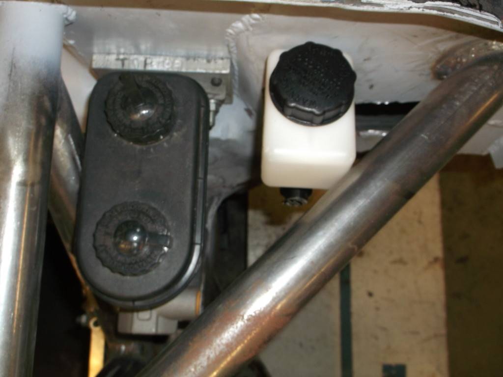
and after.
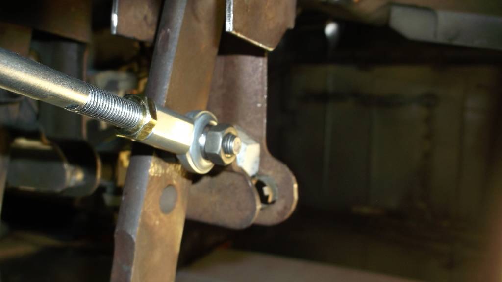
other than that it came out pretty good. I will still have to add a stop bolt to limit down travel. Mcleod supplies a pushrod with the kit. Just had to raise pin position on pedal arm for alignment.
11-17-2015 #55
Registered User
- Join Date
- Jun 2015
- Location
- kent,ohio
- Posts
- 128
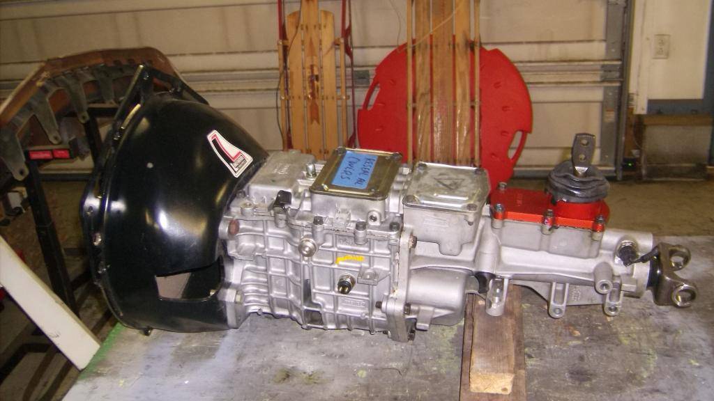
Up until now I had used the 305 and 4l60e from my old 95 c1500 for mock up purposes. I got the TKO 600 just this past summer and knew it would require some tunnel mods to fit. I pulled the motor/4l60e and hooked up the TKO with a Lakewood non SFI rated blow shield. This bellhousing is basically the same as their SFI rated units (1/4" hydroformed, 1 piece) but no block plate. Their painted black instead of red and use all the same hardware.
The flywheel for this is the lightweight 16lb GM piece that was used on the LT1 powered cars in the 90s. It is a left over from the stock car my son raced.
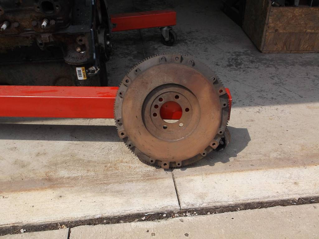
this is why it only weighs 16lbs

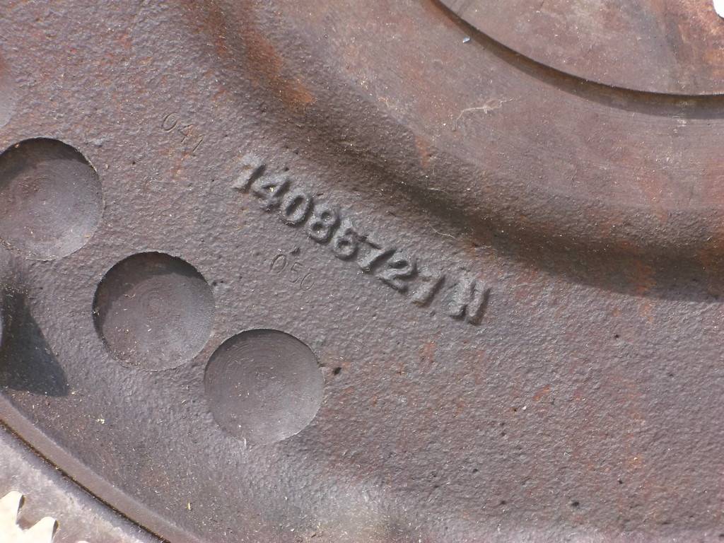
Part number
The TKO with this bellhousing has the same overall length and trans mount distance from the engine block as the 4l60e and 700r4 auotomatics so I was not expecting any real issues with my trans and engine mounts, just some tunnel mods for shifter clearance. WRONG!!!!
The body of the TKO and also the T56 do not tapper down to the tailshaft like the automatics, they stay relatively flat all the way to the shifter. This not only requires removing nearly 12" of tunnel ahead of the shifter but the height of the trans mount pad is much higher (closer to the tailshaft centerline) than the 700R4 and 4L60E autos.
When I tried to bolt the trans to my fabricated trans crossmember the tailshaft was pointing at the lower section of the front driveshaft loop. The engine and trans mounts were originally set in place with the carb pad level giving the engine /trans about 2 degrees downward angle to the rear to aid driveline angles. To raise just the rear of the trans to get things back into alignment would have had the top of the driveshaft coming out of the top of the tunnel. To correct the problem I had to lower the engine mounts an inch and fab a 1/2" aluminum spacer to lift the back of the trans. I wasn't real keen on losing 1" of ground clearance at the oil pan but now everything is back in alignment.
Modified front engine mount, it used to sit up on a 1" tall leg

1/2" aluminum spacer to raise rear of trans
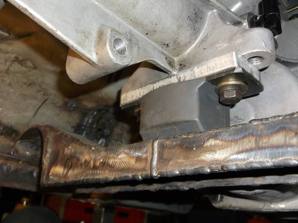
and all is good in driveline land.
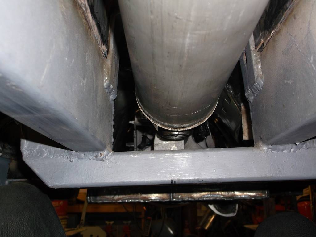

and just cleared the front of the k=member
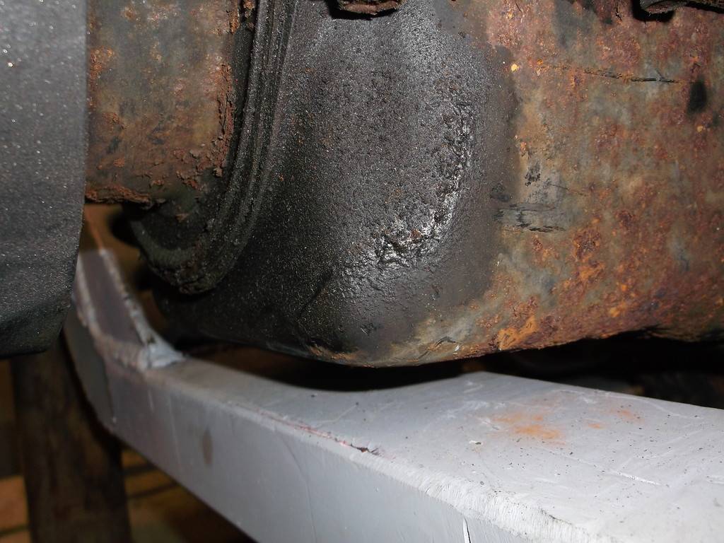
12-09-2015 #56
Registered User
- Join Date
- Jun 2015
- Location
- kent,ohio
- Posts
- 128
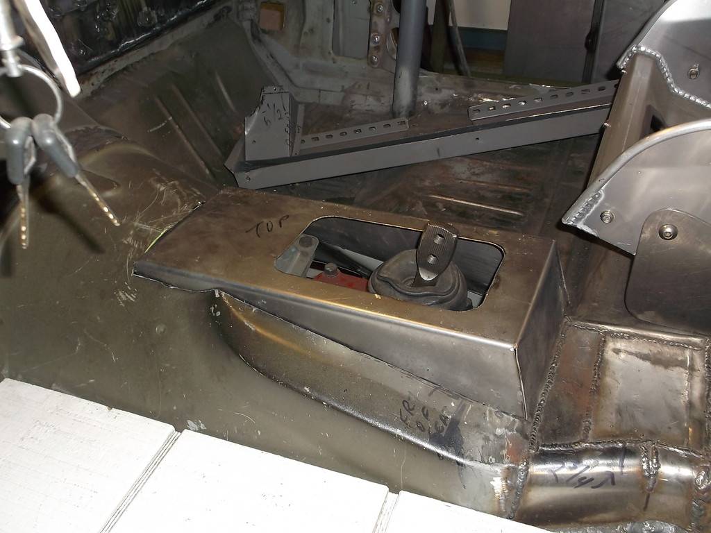
pics of tunnel modifications
here you can see just how high the shifter sits and how far forward I had to raise the tunnel. This is bare minimum as tranny clears tunnel by 1/2" or so.
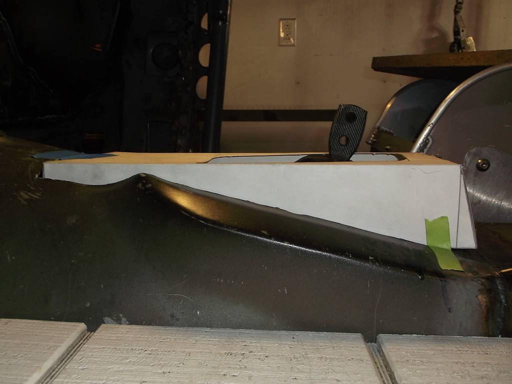
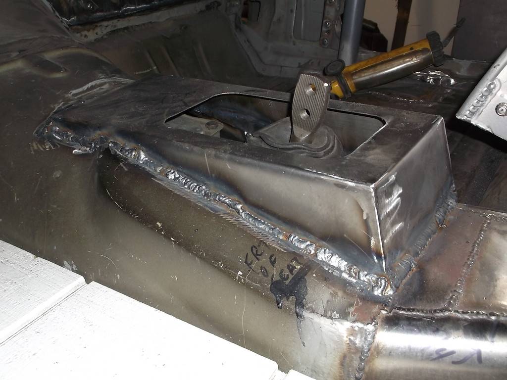
I made the top opening just large enough to remove the shifter. with the shifter out I can install/remove engine and tranny without drastically tilting them down to clear tunnel. I will fab a simple cover plate to keep dirt out.
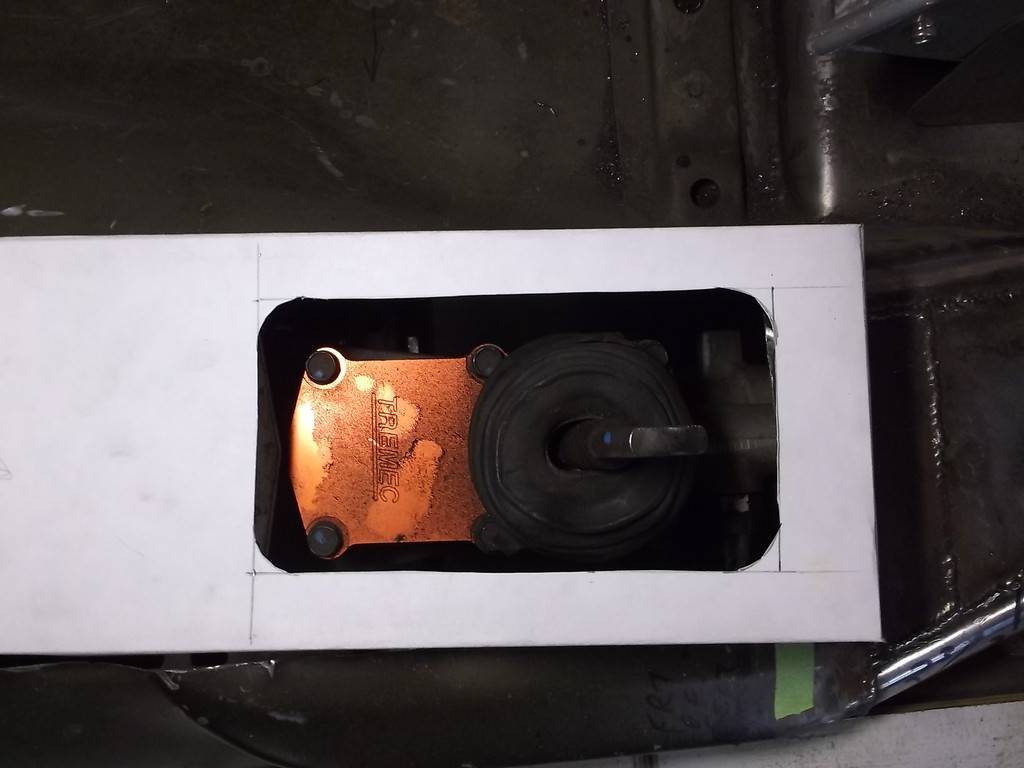
18ga metal cover from poster board pattern.

check for fitment
and all welded in.
12-09-2015 #57
Registered User
- Join Date
- Jun 2015
- Location
- kent,ohio
- Posts
- 128
Plans called for tilting the radiator forward quite a bit, running dual fans and ducting the air out through extraction vent in the front of the hood.
initial mock up. the filler neck was in the way. I can't use it any way so I cut it off nearly flush and had a local weld shop weld the hole shut.
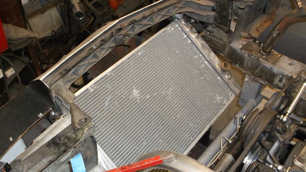
radiator mount is made from 1/8" steel strap and clamps onto tanks. Foam "camper tape" protects aluminum tanks from rubbing on mount. mount and radiator install/ remove as one piece.
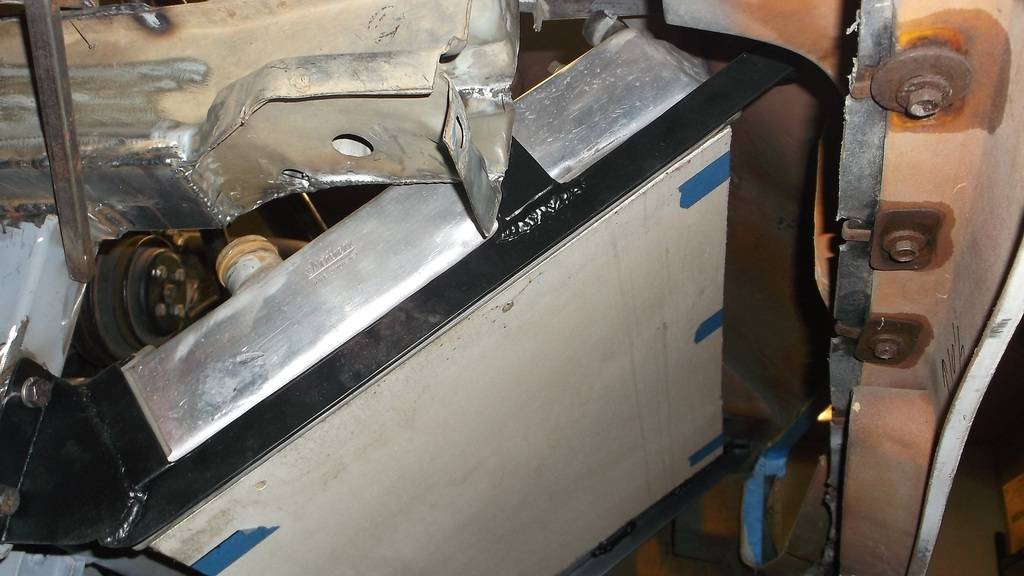
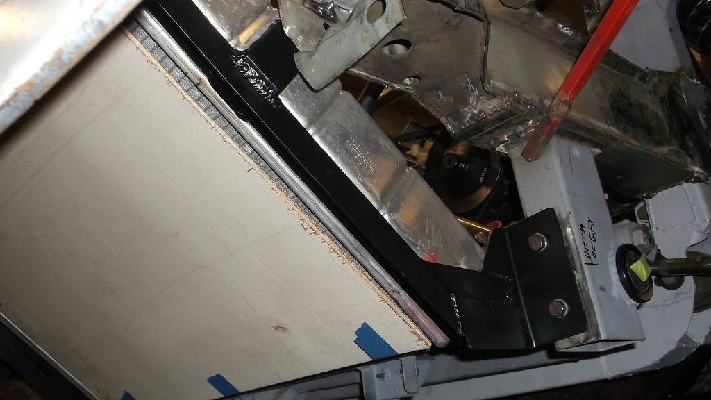

It is hard to see in the pics but there is a 1" lip all around the mounting frame that will support an aluminum shroud that will duct air from grille opening. All air to radiator will be through the grille.
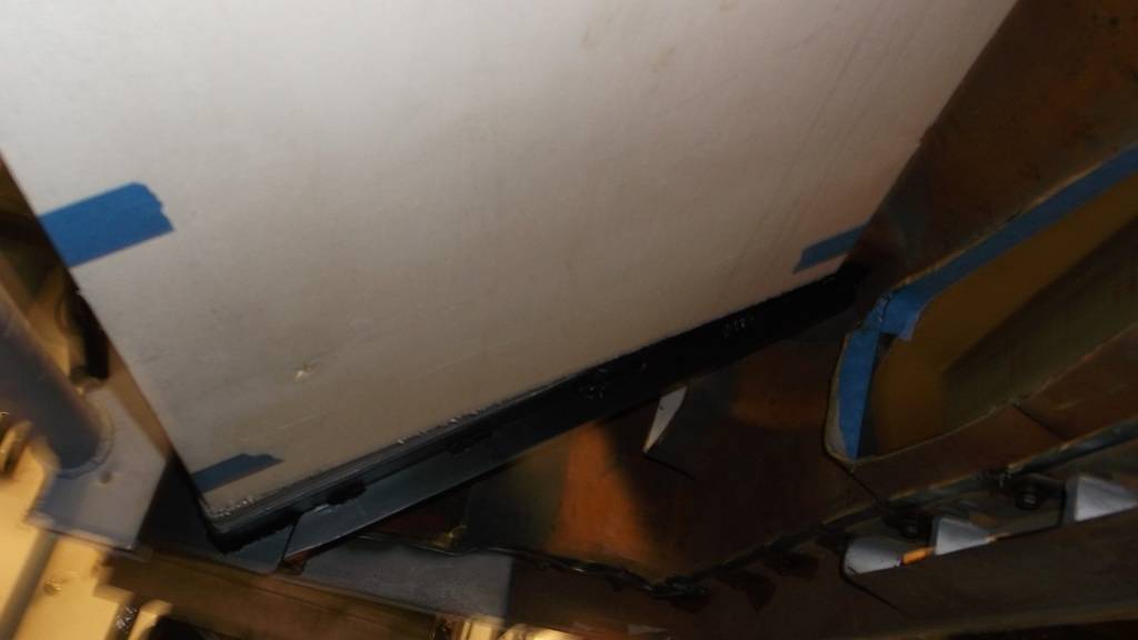
view from front. Radiator and grille match up real well.
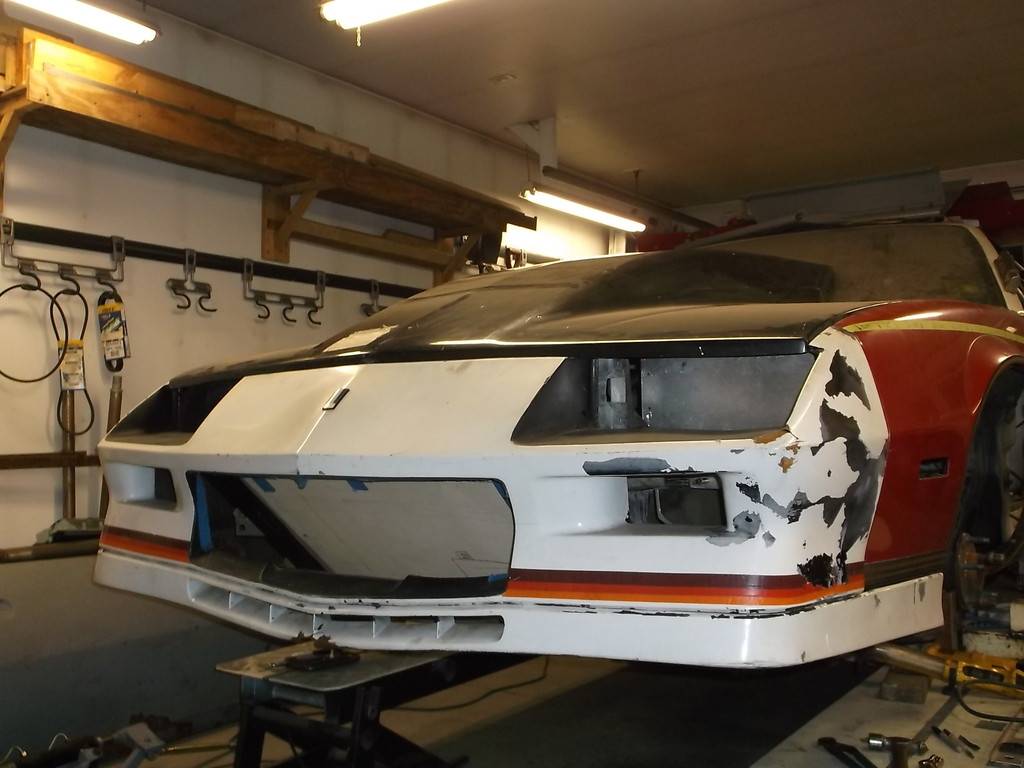
12-09-2015 #58
Registered User
- Join Date
- Jun 2015
- Location
- kent,ohio
- Posts
- 128
one of the above pics showed the x-brace that I wanted to make to tie upper and lower frame rails together ahead of the engine. It is located far enough ahead of the engine that all of the engine accessories can be serviced without removal. The brace angles back at the top and the plan is to face it with aluminum sheet and have it and some side panels direct the air to the extractor vent in the hood.
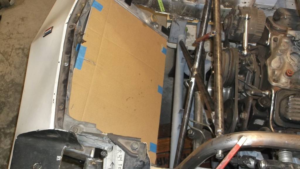
and done.

I also needed to get rid of the rest of the core support that mounts the headlights and fenders. After making temporary mounts to hold the fenders in place I cut away the remaining factory core support. Using 1 x 1 .065 tubing I made a simple frame that would support the front fender and the factory rubber nose. To mount my APV mini van headlights I formed some panels from 1/8 aluminum sheet. This was a remnant I got from the weld shop and turned out to be hardened 6051 grade. Man was it hard to bend, so please excuse the hammer marks on the top edge.
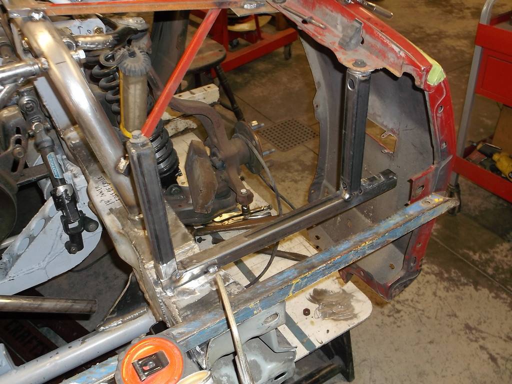
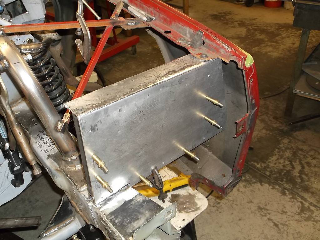
Even though the mount extends far out from the frame rail it proved to be very sturdy. with the aluminum bolted to the steel frame it acts like a shear plate and made the mount very stiff.
With the mounts in place it was time to see if the body panels still fit up. After fore/aft adjustment on the fenders it mocked up pretty well.

don't be alarmed by the big 6" Harwood cowl hood. I bought it years ago on clearance for about $100 so I won't feel bad about cutting it down to 2 1/2" and putting an extractor vent in the front.
Here you can see at the back of the scoop how much I will have to chop it down.
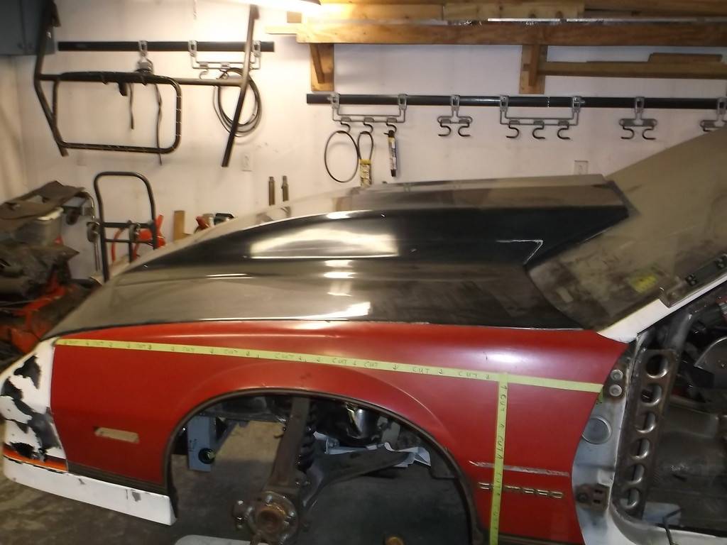
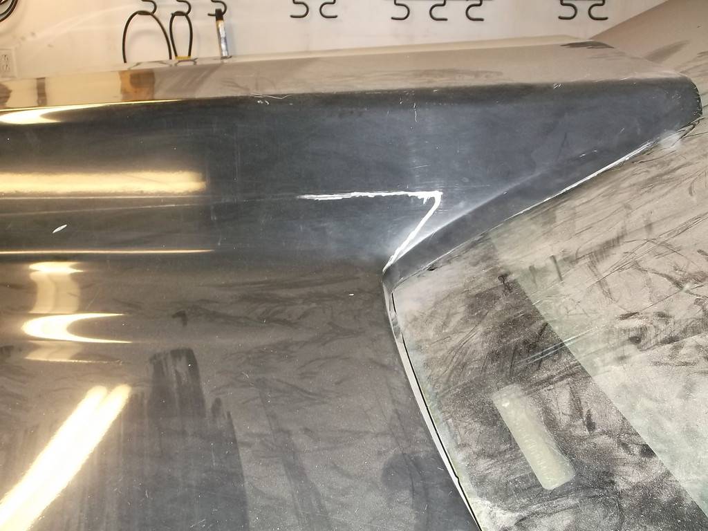
I still have to section the front fenders and move the wheel opening 5" forward and up maybe 2". Not quite sure how I want to go about this. These fenders are in fair/poor condition, so a good practice set. Once I get it how I want it I'll duplicate it on some new repops, tack it together and give it to a real body shop to finish.
01-13-2016 #59
Registered User
- Join Date
- Oct 2014
- Location
- Seattle, Washington
- Posts
- 6
Hell of a project you've got here. A lot of ambition, and even more welding in this Camaro; I have to give you props for trying something new in the world of third gens.
01-14-2016 #60
Registered User
- Join Date
- Apr 2014
- Location
- Shoals, IN
- Posts
- 13
Just went through all the posts. I love it.


 Reply With Quote





