


Results 1 to 20 of 138
Thread: 3rd gen Z28 track day build
Hybrid View


-
08-17-2015 #1
 Registered User
- Join Date
- Jun 2015
- Location
- kent,ohio
- Posts
- 128

3rd gen Z28 track day build
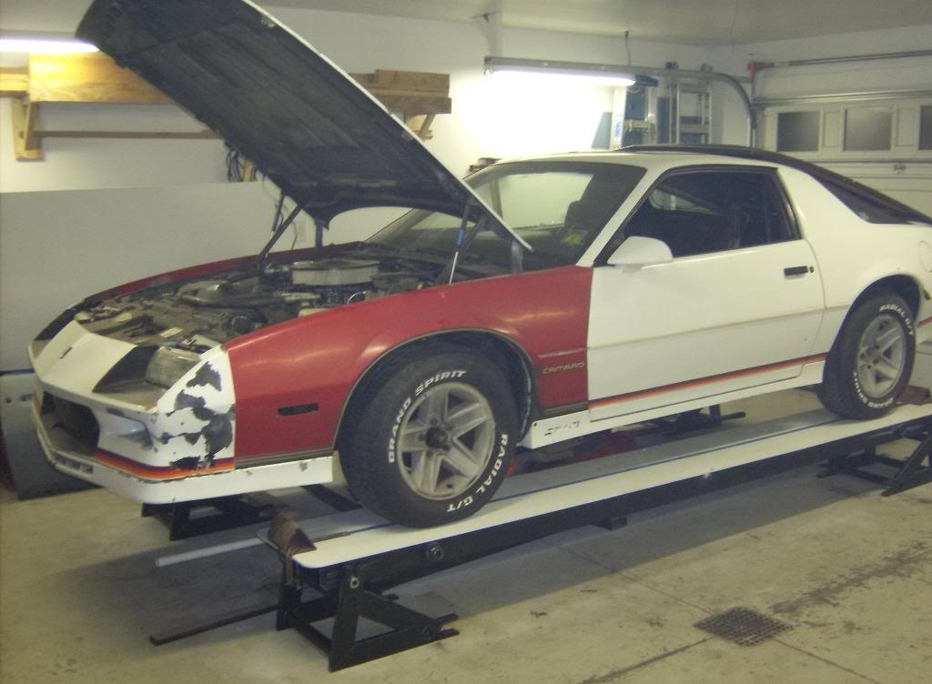
Hey folks, kind of a newbie to PTO but have been posting my build thread at thirdgen.org over the past 4 years (Fabrication forum, "home brew road racer"). The car started out as a clapped out but solid, rust free beater from SC. Car was hit in left front hard enough that it bent the front frame rails ahead of the k-member. Originally bought the car for parts but when saw how solid it was decided to use as the basis for my track day car. I had the frame straightened by a reliable body shop, drove it for a few hundred miles to make sure it was OK and then set to make it into a very capable track car.
I am building this car on a very tight budget and which dictated that I make most of the suspension parts rather than buying off the shelf stuff so this is no cookie cutter 3rd gen. I really disliked everything GM designed into this car except the body. I have designed and installed a 3 link rear suspension with coilovers, replaced or reinforced the unibody with rectangular tubing, added a full cage and finally replaced the strut front end with an SLA suspension from a 2000 LS Camaro.
I am a wannabe road racer and the extent of my driving experience is completing the 3 day HPD school at Mid Ohio so I could qualify for their lapping days. Now all I have to do is get the car done.
Her we go....
Car before mods
swapped out the little 7.5 dif for an 8.6 from a ZR2 S10 truck (3.72 gears, posi, 30 spline axles and disc brakes.
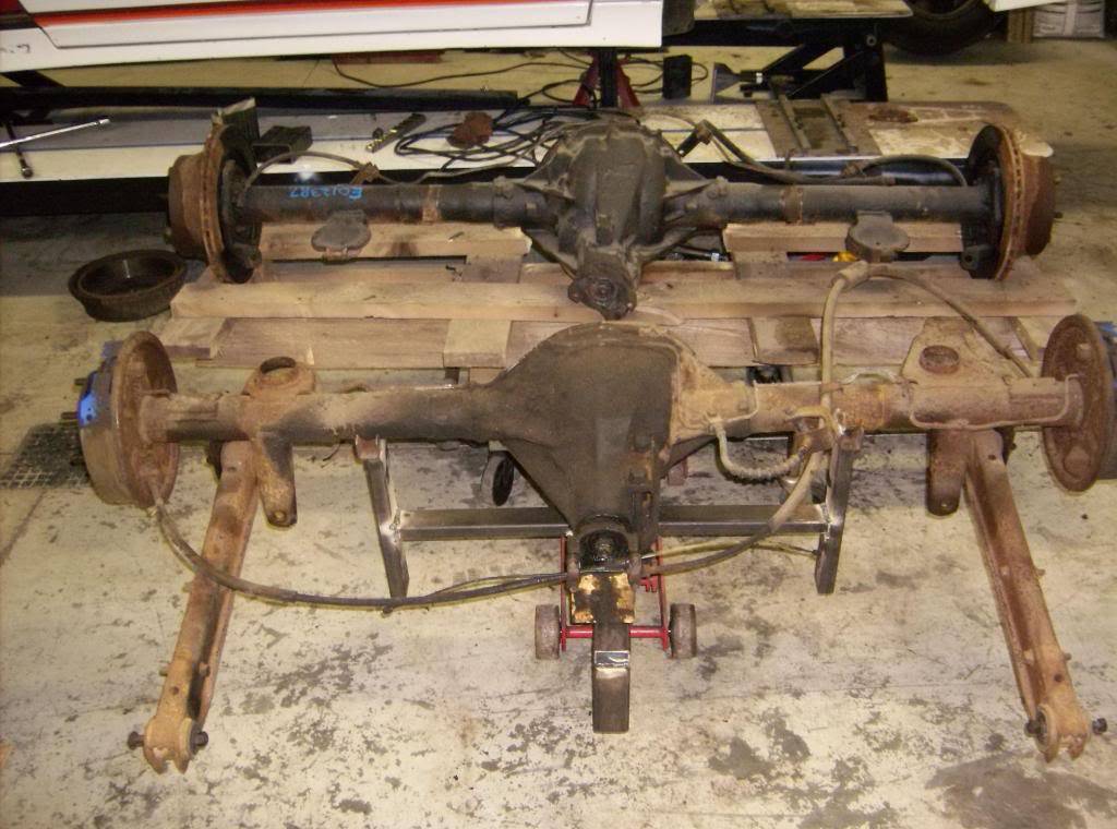
I designed and built the ramps to serve as a chassis jig of sorts. When done with the project I can use them for maintenance for all my vehicles. I made these plates and stands to locate the rear axle. I mounted them to the OE axle and marked its location. Swapped in the ZR2 axle and set back in place.

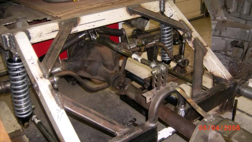
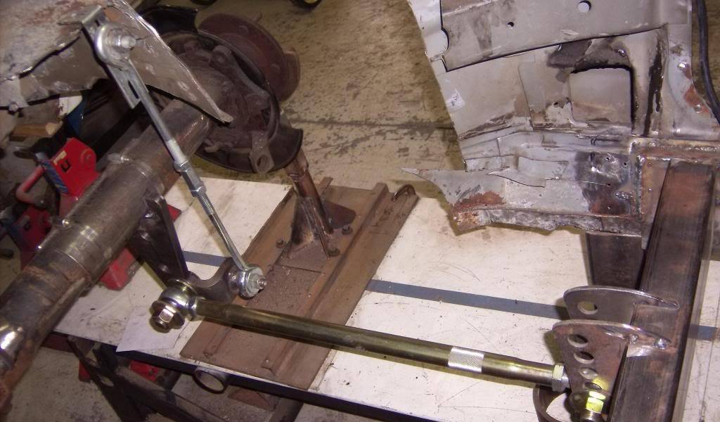
Long before I had the axle I designed the 3 link suspension. I plotted pick up points and control arm lengths that would give me adjustments for pinion angle, anti squat, roll center height, ride height etc.
-
08-18-2015 #2
 Registered User
- Join Date
- May 2009
- Location
- Connecticut
- Posts
- 409
Looks great so far. I will be watching this one.
Aldin
1969 Camaro (Weapon of Choice) in the works
08-18-2015 #3
Registered User
- Join Date
- Jun 2015
- Location
- kent,ohio
- Posts
- 128
Thanks for the post Aldin. Like I said this car is being built on a pretty tight budget, probably $7500 tops for everything. There are literally hundreds of great build threads on PTO but most include mountains of parts that they bought and bolted on or had a professional shop fab up something special for them. I can't afford either so ZR2 axle will have to do in place of a Currie or Moser 9".
I had big ideas for some major changes to this car and had to figure out how to get what I wanted using the tools, materials, abilities and money I have. There are no plasma cutters, tig welders or mandrel tubing benders in my garage. The most high tech tool in the garage is a 135 amp Lincoln mig welder. Everything gets cut with a chop saw or 4 1/2 cutoff wheel. hopefully I can accomplish most of what I set out to do. I have been working on the car for over 4 years now and it is about 75% finished. All of the major suspension fab work is done and with a little luck I can get the under carriage and engine compartment sand blasted and painted yet this fall and start final assembly of the powertrain and plumbing.
08-18-2015 #4 Registered User
- Join Date
- Sep 2005
- Posts
- 321
Great looking project and nice 3-link
1972 Camaro ( my retirement money hole )
1985 GMC ( future plan pro tour build for the wife )
1992 Isuzu pup bagged, bodydrop, shaved everything
2013 GMC Single cab 4/7 drop
08-18-2015 #5
Registered User
- Join Date
- Jun 2015
- Location
- kent,ohio
- Posts
- 128
Xtreme, thanks, for looking in on my insanity. I started this project at the rear because it was easiest to design and I pretty much new what I needed to do before I even started. Here are a few picks of the finished rear axle assembly and frame mods. Please note most parts have yet to be sand blasted and painted.
Rear axle
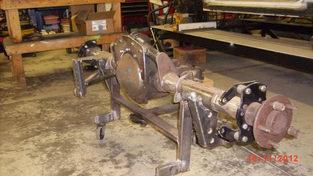

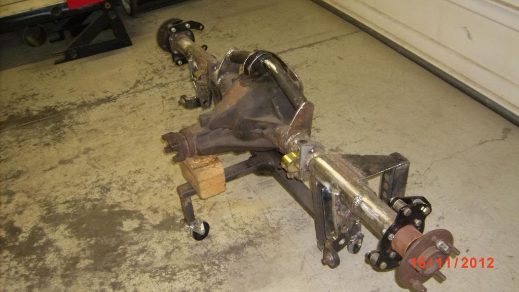
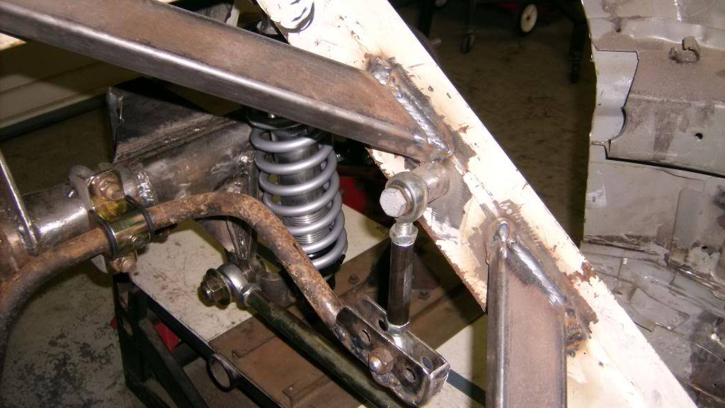
The panhard bar bracket and the LCA/shock moun brackets are Allstar brand parts purchased through Summit Racing. Same for the control arms, Allstar tubes and QA1 rod ends. The flat plate bolted to the rear end cover was added to give the top link mount more lateral and fore/aft support. I tried to get the top mount inline with the lca's so I could use the same length control arms. Stock 3rd gen were 19" long and my redesign set them at 23 1/2". The extra length should help minimize roll steer.
Panhard bar was shortened about 3 1/2" from stock and moved inboard so no interference if running 315/35/17 or wider tires. panhard bar and brace are aluminum hex with 3/4 rod ends. It is adjustable from 7" above ground to 13". Coilovers are QA1 single adjustables with 200lb springs. Springs might be to stiff.
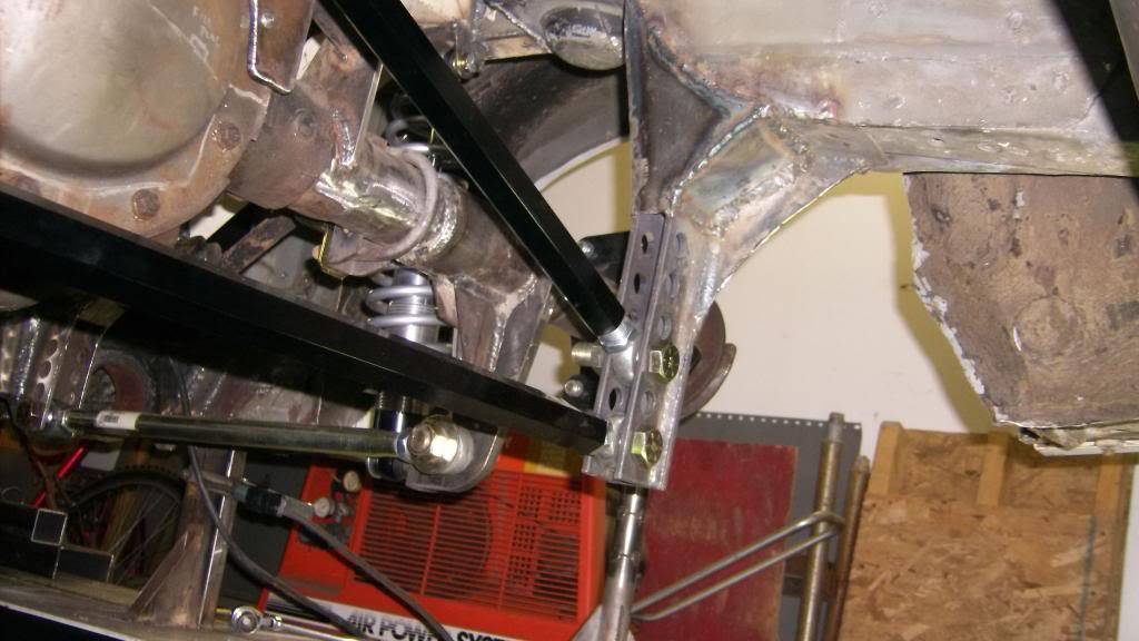
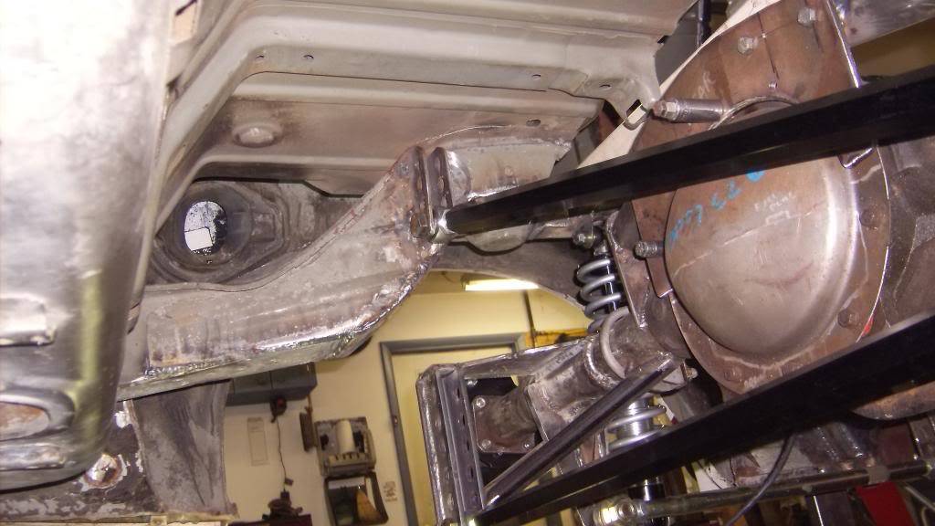
The white rectangular tubing is 2x3 w/.125 wall. This came from a professional quality squat bench I bought from a semi pro weight lifter at a yard sale. I got over 80 usable feet of this for $125.00. The sway bar is 24mm from the ZR2 but installed upside down. I didn't have this in my design but it fit like it was made for it. End links are 1/2" and I modified the end of the bar so I could lengthen or shorten 1" to fine tune.
08-20-2015 #6
Starting The Transformation
- Join Date
- Jan 2015
- Location
- Charlotte, NC
- Posts
- 309
Creative fab work!
08-24-2015 #7
Registered User
- Join Date
- Jun 2015
- Location
- kent,ohio
- Posts
- 128
Justin, thanks for looking in. With my lack of skills, money and equipment I have to fall back on my imagination to get where I want to go. Sometimes I come up with the most simple solutions to what looks to be a very complex problem. I think, no way can that work, but it does. Originally Posted by Justin@EntropyRad

Back to the build now. The factory ride height on this car was about 9" at the bottom of the rocker panel. My plan called for 5". To get the car that low and still have adequate suspension travel I had to cut away a lot of the rear frame rail and box it back in for strength. I have 3" upward suspension travel with these mods.
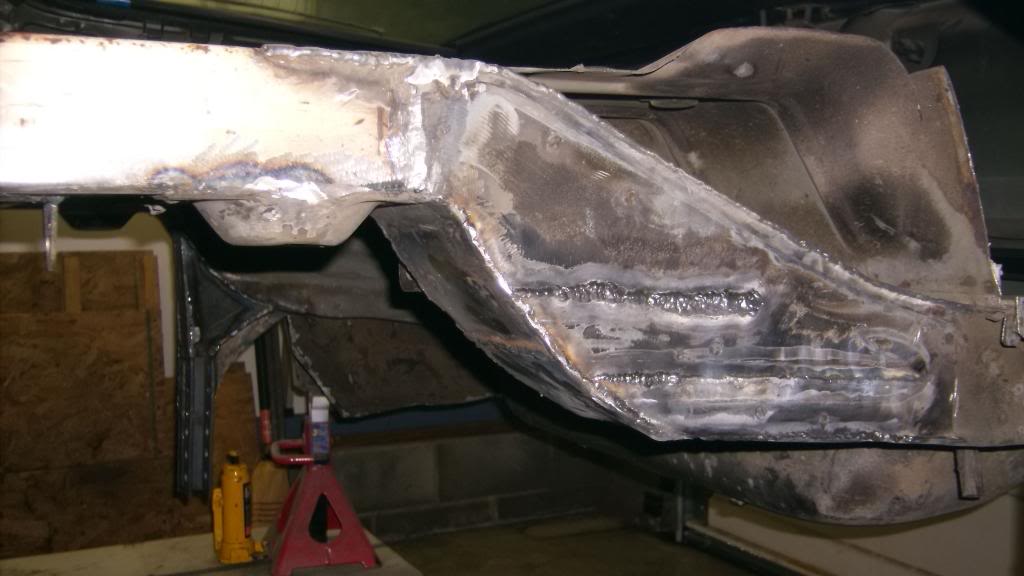
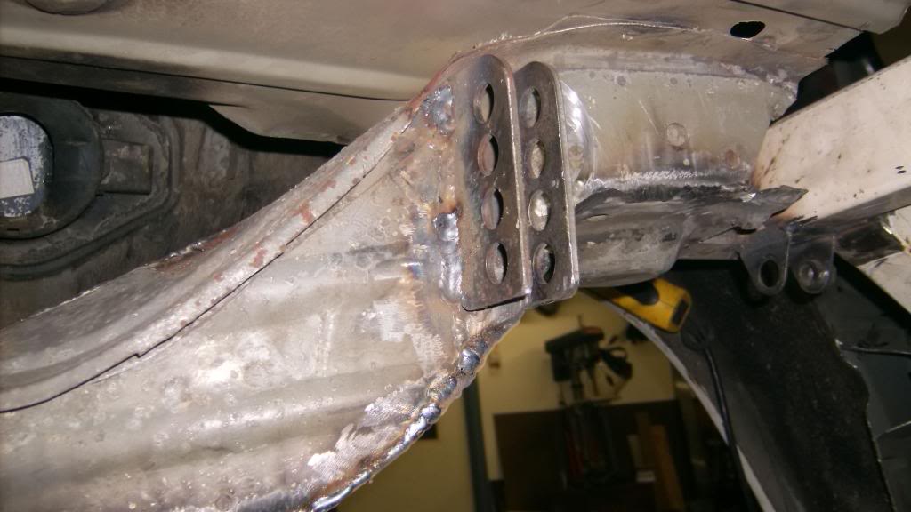
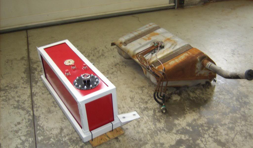
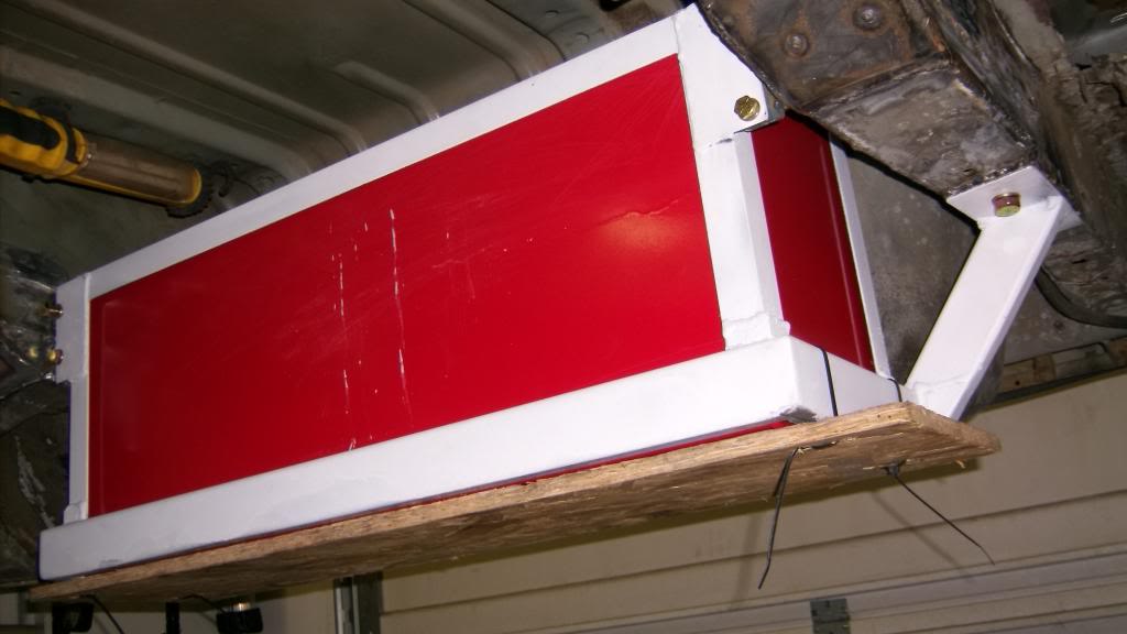
With the rear axle in place I moved on to the fuel tank. Part of the factory tank sat above the rear axle. With the car lowered this much that wouldn't fit. I wanted a fuel cel that would fit behind the rear axle and allow me to keep the rear trunk floor intact for fire protection. I wanted the fuel tank under the car not in the car like so many 3rd gens done. I settled on an RCI 15gal cell which is the same capacity as stock. Its not an ATL fire safe cell but it is under the car and well protected.

Built angle iron and rectangle tube cage to hang it from car.

new tank vs old
and mounted under car. wood sheet on bottom was replaced with 1/4 aluminum diamond plate.
08-24-2015 #8
Registered User
- Join Date
- Jun 2015
- Location
- kent,ohio
- Posts
- 128
Next on the list was the front frame rails that run along side the trans. On 3rd gens they taper in at the back to where they almost touch the pan on a 700R4 trans. This is why there is no room on these cars for true duals that don't drag on the ground. I set out to relocate the rails to run 2 1/2 or 3" exhaust.
factory rails right side
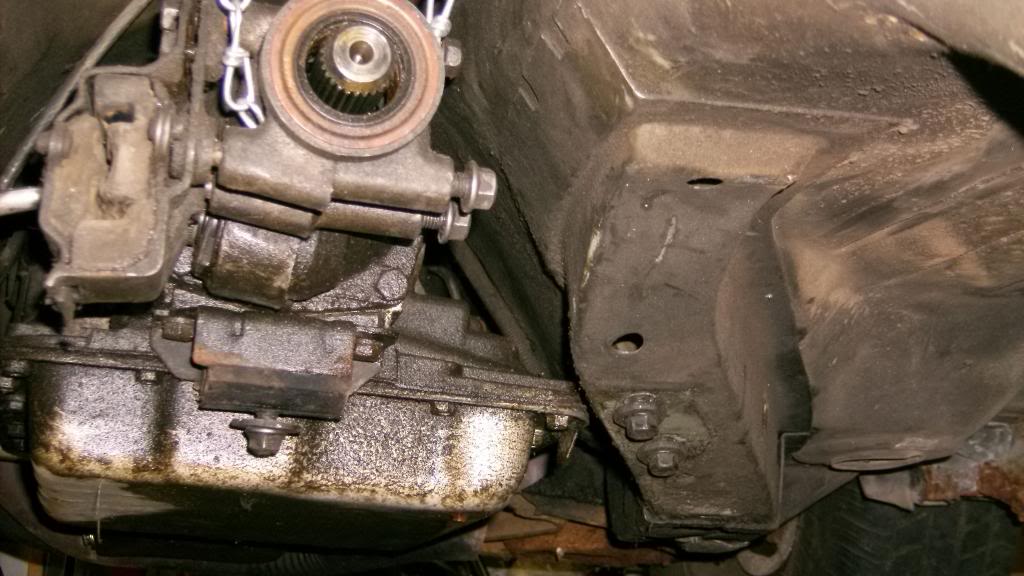
left side

cut out left side rail and made narrower and straighter replacement.
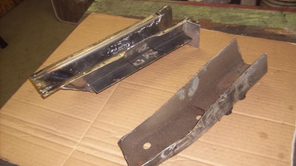

driver side rail bolted in place with new fabricated trans mount.
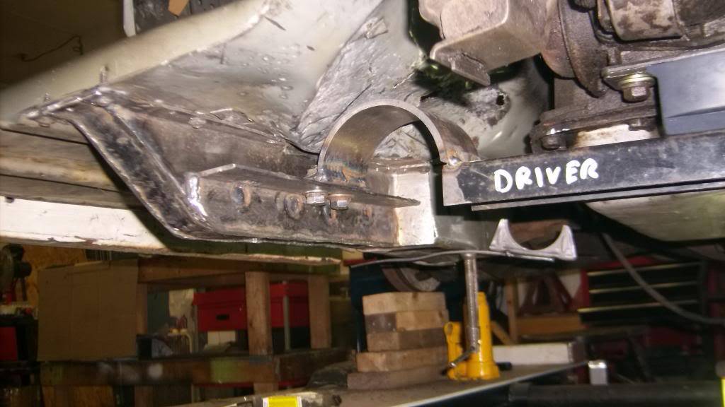
looking in from left rocker panel replacement frame is almost seamless.
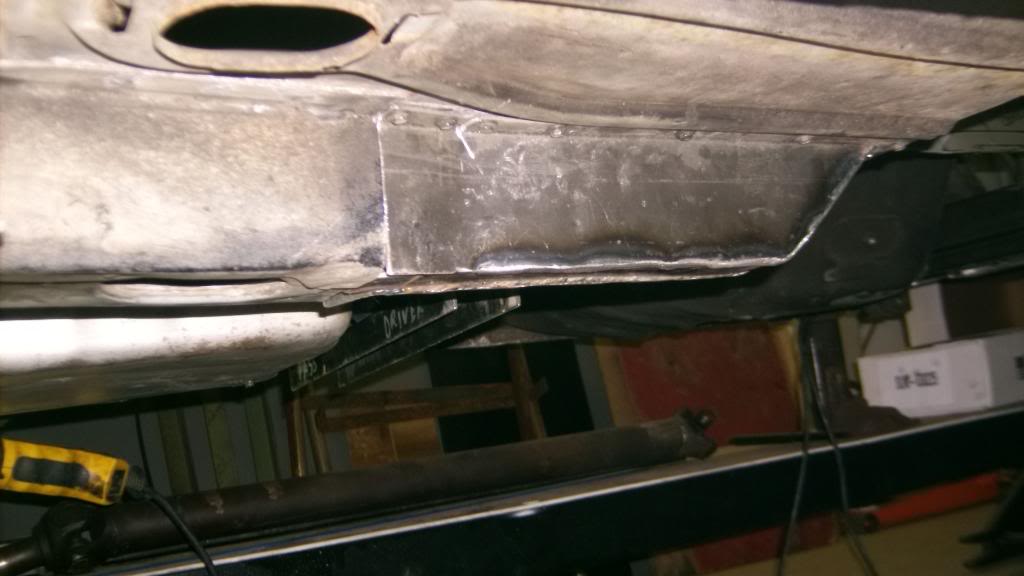
And now there is room for a left side exhaust pipe.
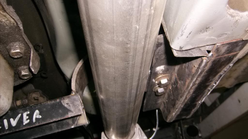
08-25-2015 #9 Registered User
- Join Date
- Mar 2006
- Location
- Lowell, MI
- Posts
- 403
Nice job on the frame rails, they have always bothered the crap out of me too.
Turbo Charged LS1/T56
09-05-2015 #10
Registered User
- Join Date
- Jun 2015
- Location
- kent,ohio
- Posts
- 128
The passenger side was a bit more involved because of the big hump in the floor for the stock catalytic converter. I used strips of 1/2 x 1/8 sheet steel to copy the shape of the floor and then transferred that to some 1/8 sheet to make the new frame rail. I used the 1/2 x 1/8 strips as mounting flanges for the rail.
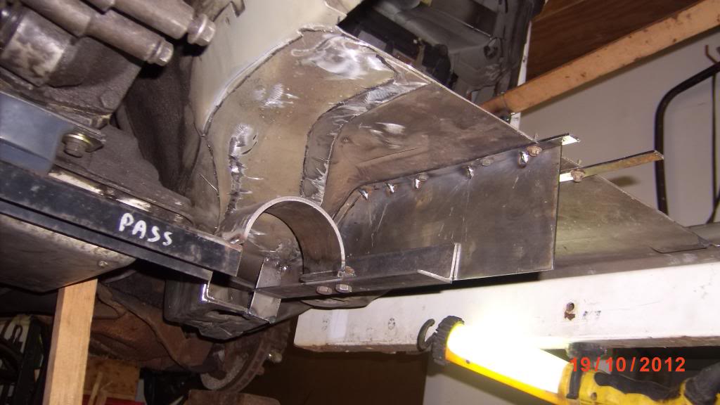
rt side rail with trans x-member. The long angle iron x-member mounting flange will let me mount any trans from powerglide to t56 to 4l80e. You can see in this pic just how far the right side rail had to be moved in order to get clearance for the exhaust to pass along side the transmission.

09-05-2015 #11
Registered User
- Join Date
- Jun 2015
- Location
- kent,ohio
- Posts
- 128
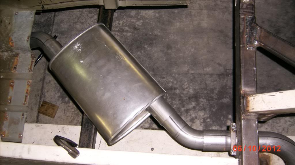
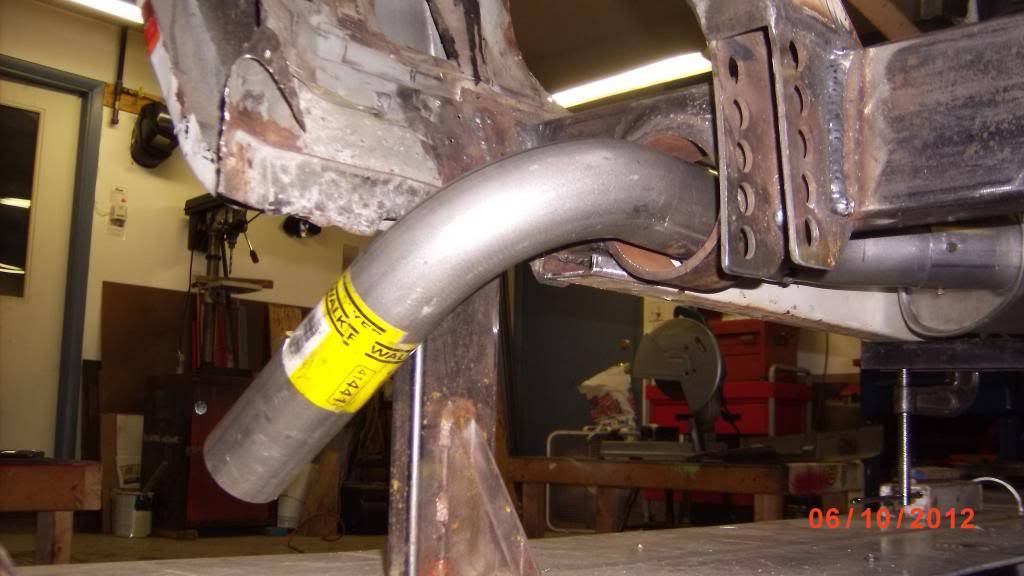
My plans called for the floor pan from the front of the drivers seat to the rear of the door jamb to be raised nearly 5" so that the mufflers could tuck up under the floor and not hang down below the subframe connectors.
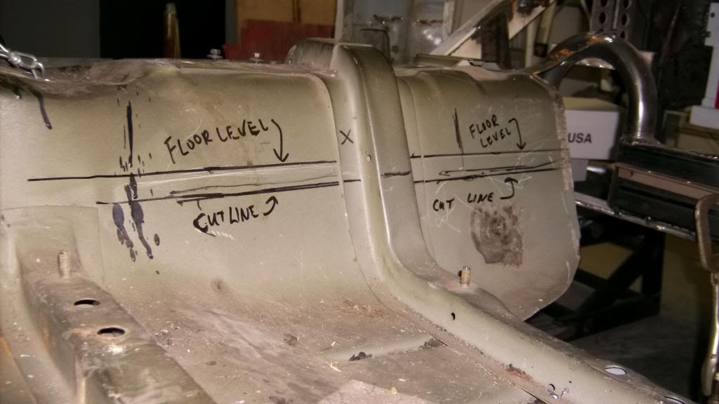

The subframe connectors were made from some of the 2x3 weight bench tubing and run the full length of the rocker pinch weld. SFC's are completely stitch welded to the pinch weld at the bottom and also along a filler piece of sheet steel was added at the top along the entire length to close off the gap between the sfc and the inner rocker, as it angled out and away from the sfc.
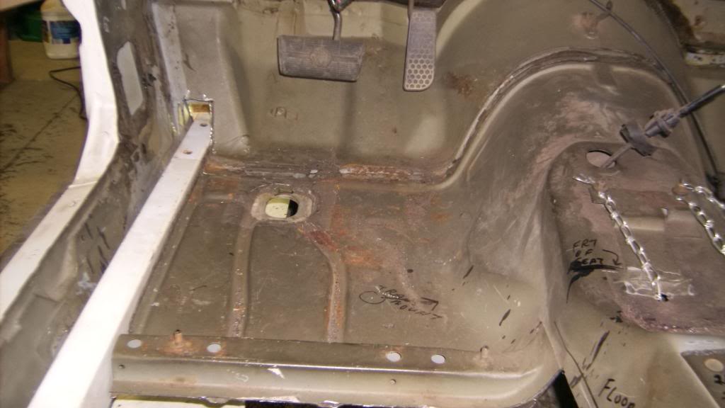
the exhaust would run under the seat something like this.
and exit out the rocker ahead of the rear wheel. please note the rocker has not been cut out yet.
09-05-2015 #12
Registered User
- Join Date
- Jun 2015
- Location
- kent,ohio
- Posts
- 128
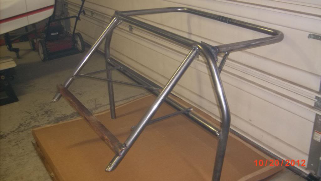
When I first made the sfc's I temporarily mounted them with several screws through the rocker pinch weld. I knew I was going to be installing a roll cage and by having the ability to drop the sfc's down I could gain full access to the top and bottom of the cage to fully weld around the joints. I don't have access to a tube bender and ordering a custom cage was out of the budget so I got a pre bent 10 point kit from Comp Engineering. It is 1 5/8, 1.35 mild steel. Yes I know it is not SCCA legal but this is a track day car and I did add extra bracing around the driver area and tied the cage to the body at every concievable location.
I wanted the cage to be as high up into the roof area as possible so I cut out most to the roof supports.

Same for the halo bar


To maximize frame rigidity I placed the rear struts over the rear coil over mounts.

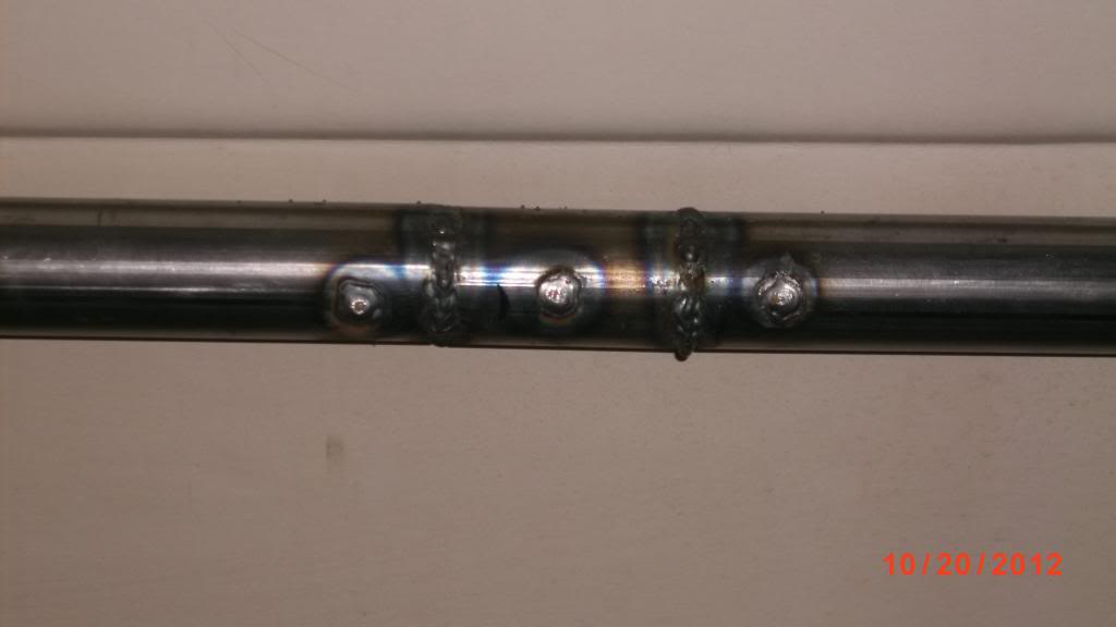
To get maximum head room I widened the halo bar about 3" at the front center so it would fit tight to the body at the door opening. I used a 6" piece of 1/8 wall tubing that fit snug inside the halo bar and spanned the 3" gap with a short piece of the 1 5/8 roll bar tubing. I plug welded the inner 6" tube to the outer tube and after leaving about an 1/8 in gap between the original halo tube and the short 1 5/8 piece I welded all 3 pieces together. This section of the halo bar is probably 3 times stronger than the rest of of it.
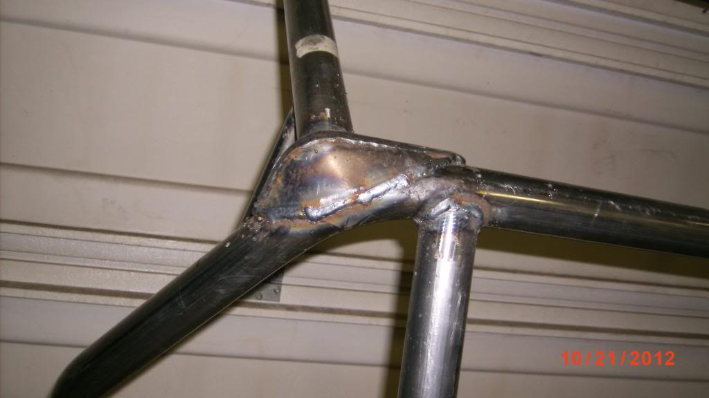
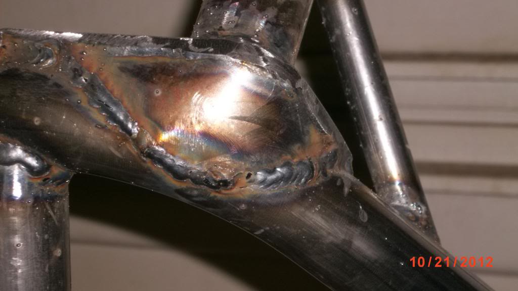
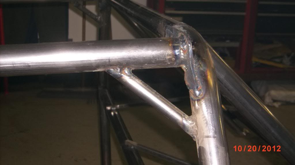
With the halo bar 3 inches wider it now fit snug between the door openings but was a little too wide for the main hoop. To fix this I added some 1/4" thick "ears" to the main hoop to attach the halo bar to. I fully boxed the ears with 1/8 sheet steel. diagonal braces are 1/2 x .083 tubing.

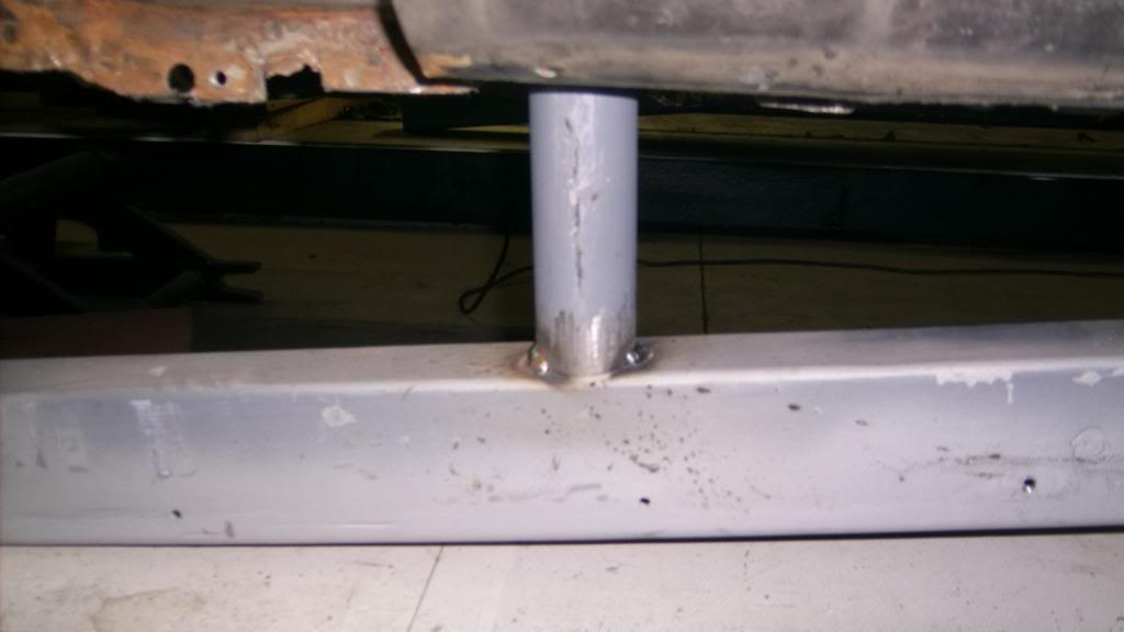
The 4 legs of the cage are welded directly to the sfc's. When I fitted the cage I just tack welded the legs to them and then cut it loose to take the cage out of the car where I could easily get to all sides of the connections so they could be fully welded. I did have to remove the front legs of the cage to get out of the car, but with a 60" door opening getting the rest out was easy.
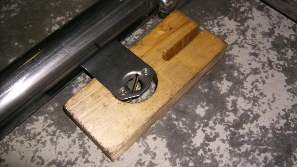
With the halo bar so high there was no room for a headliner and that would make for a pretty hot interior. I added quick fastners to the inside of the halo to hold a new headliner.

09-05-2015 #13
Registered User
- Join Date
- Jun 2015
- Location
- kent,ohio
- Posts
- 128
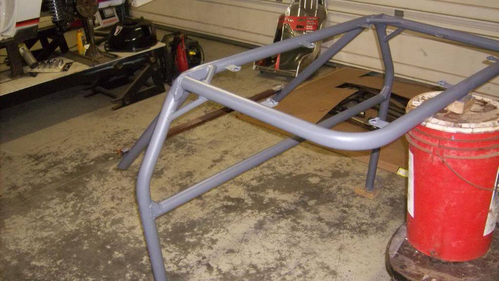
I added a few extra braces to the main hoop and halo, then sanded and primered it with epoxy primer.

With the main hoop and halo fully welded together I put it back in the car and refitted the front down legs, tacked them in place to the halo and sfc's and then unbolted the sfc's and dropped the cage down through the floor.
Access to top of front legs
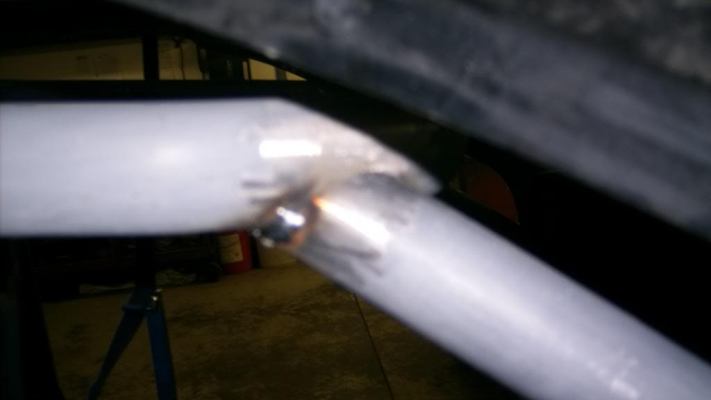
Full welds
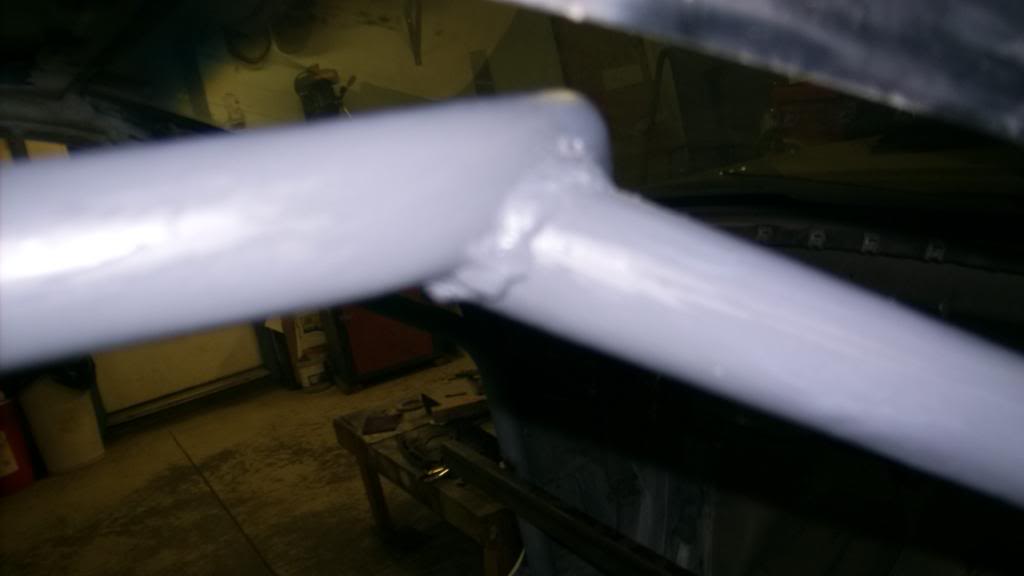
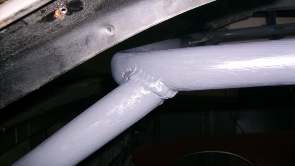
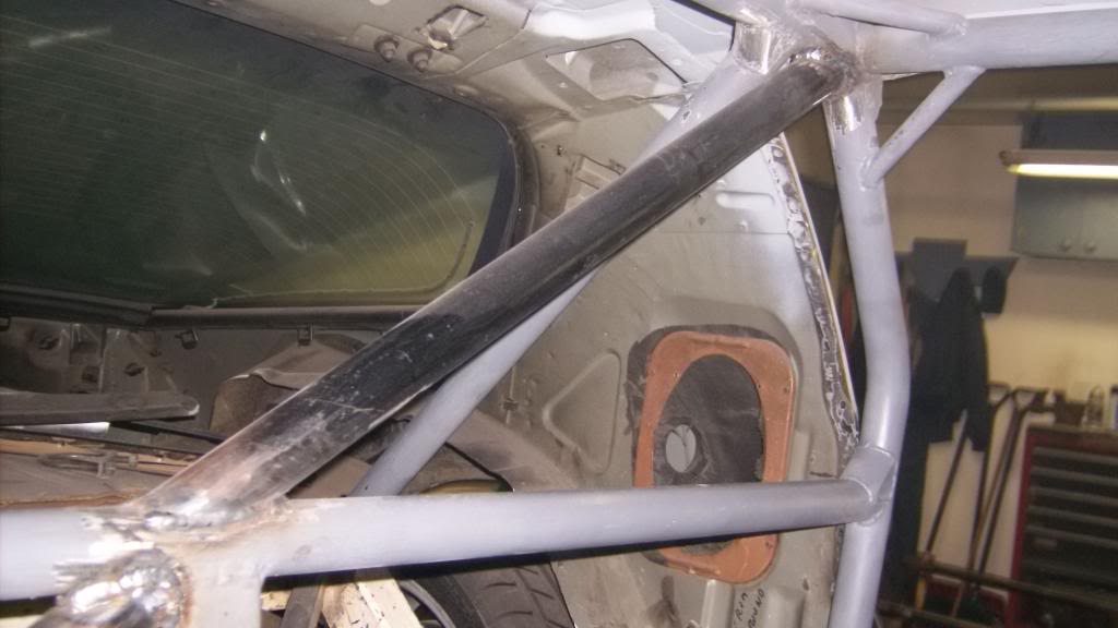
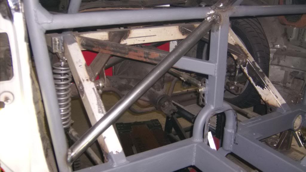
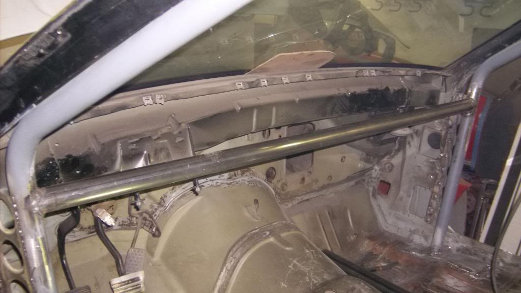
With the cage back in place I added a cross brace behind the driver and a knee brace above the steering column.
09-05-2015 #14
Registered User
- Join Date
- Jun 2015
- Location
- kent,ohio
- Posts
- 128
I mentioned earlier that I wanted to put an x-brace under the passenger area to tie the sfc's together. That didn't work out because of exhaust clearance issues. I ended up making a forward crossmember just behind the transmission tailshaft and adding two inner frame rails running between the new cross member and the rear crossmember framing in the driveshaft. all of this was made from 1 1/2 x 4 x .125 rectangular tubing.
Here it is being mocked up. Notice I had to go with a smaller case muffler a Magnaflow 14x9.

cut front crossmember for exhaust pipe. Used a 4" hole saw.
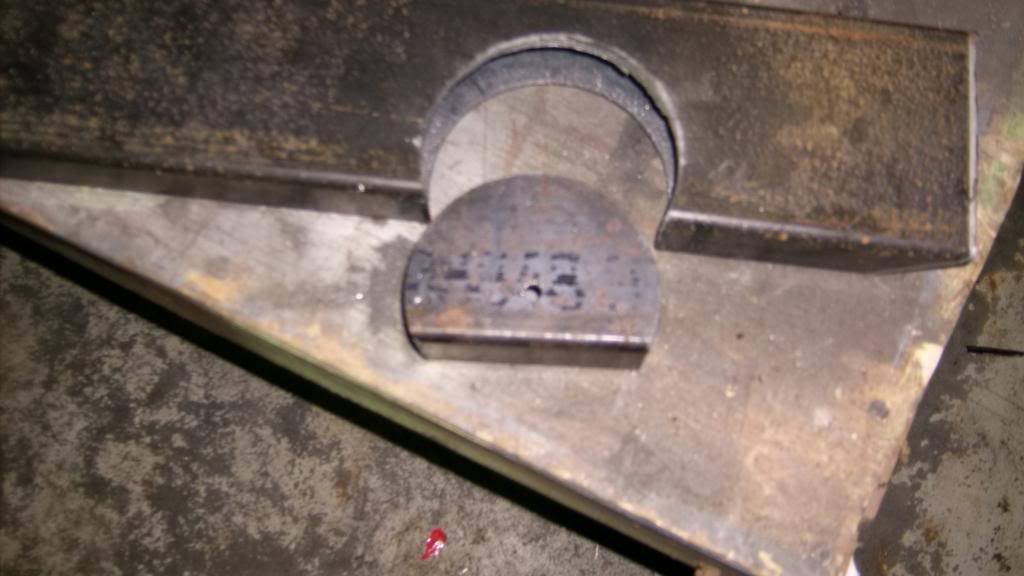
Boxed in the cutout with 2" x .125 strap steel. Used the plug to help shape the strap.
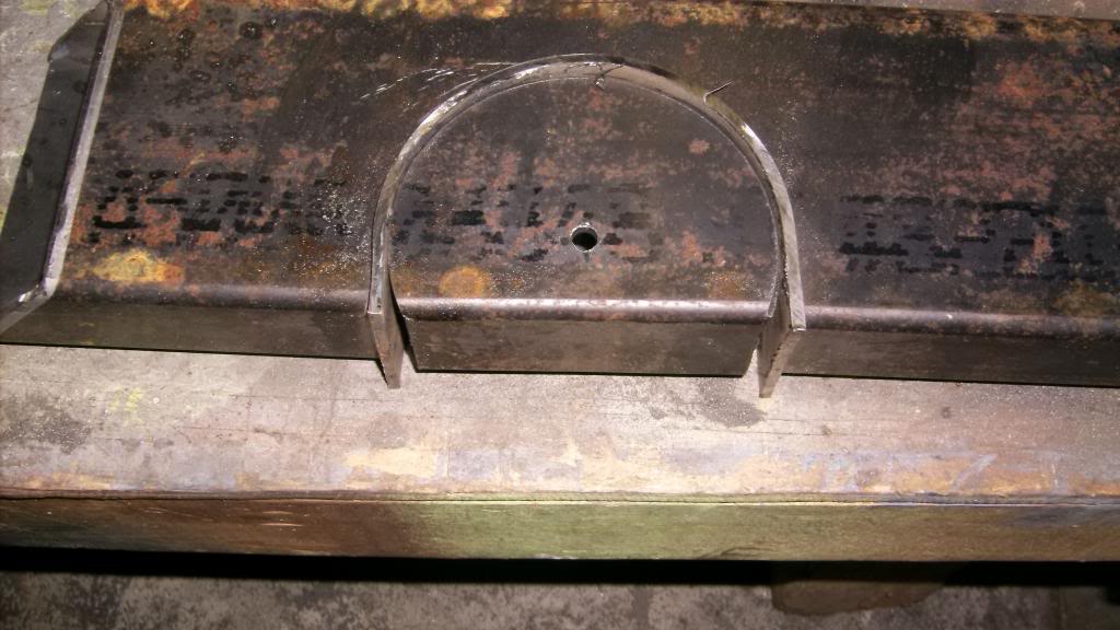
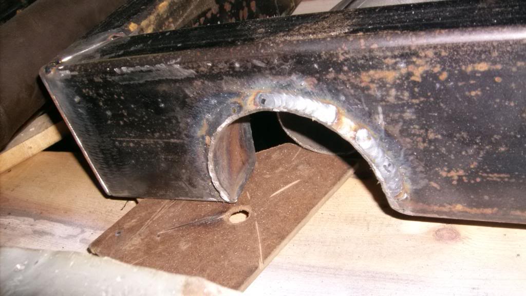
and tacked in place.
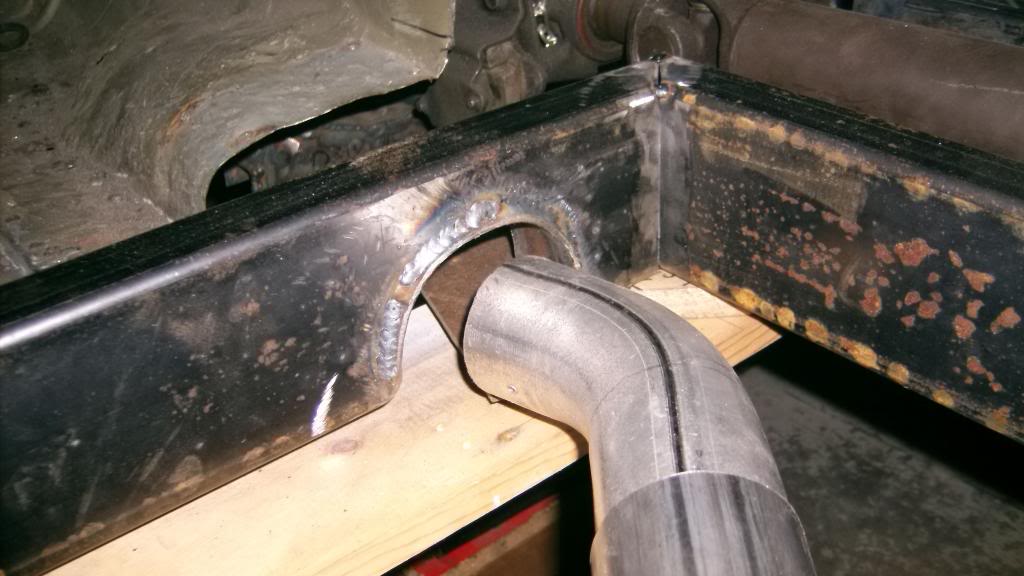
All painted up you can see how it ties front and rear frame sections together and both subframes. I like the idea of having two substantial crossmembers protecting the driver in a side impact. You can also see the seat and seatbelt mounting brackets. These are 1/4 x 2 steel welded to the sfc's, the front crossmember and the inner frame rails. These sit below the floor pan.
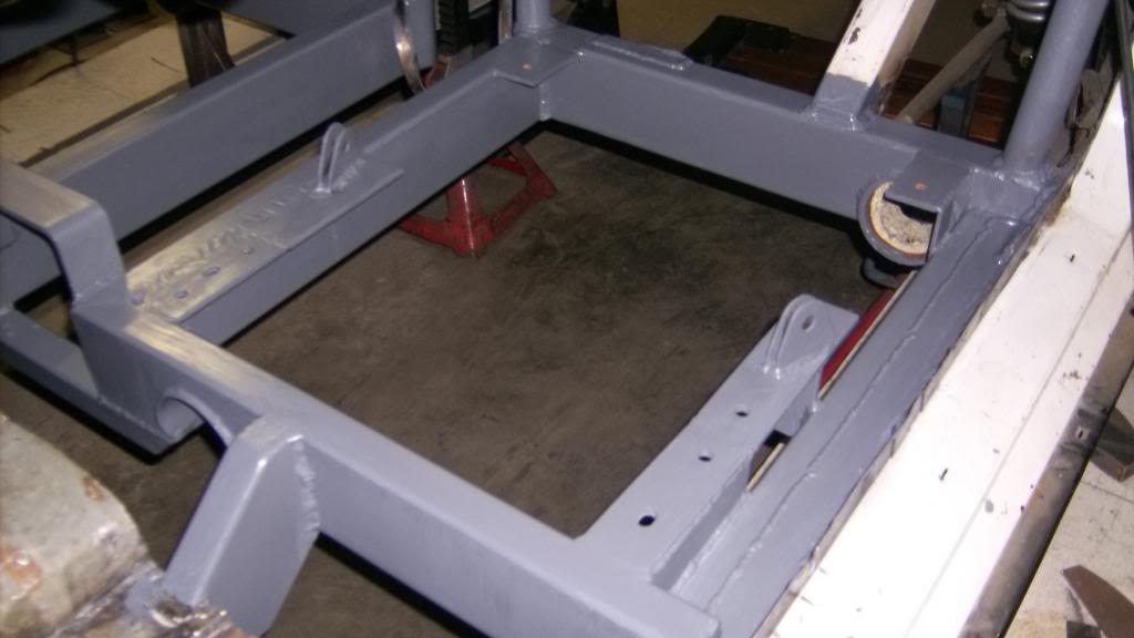
At the front you can see the cutouts for the exhaust and a full 360* driveshaft loop.

from underneath
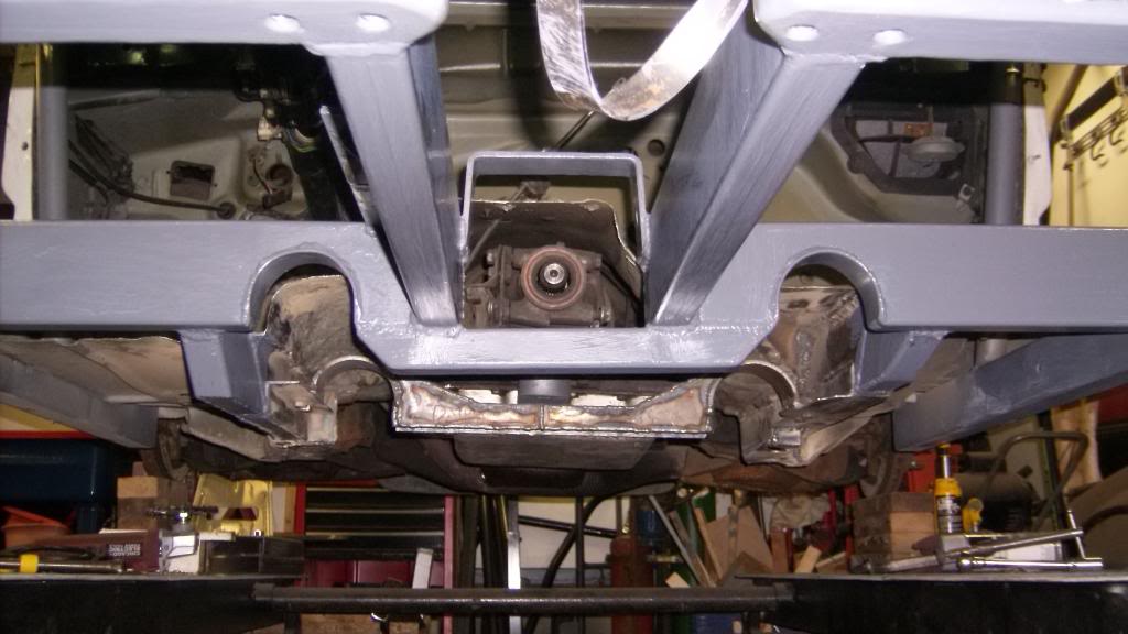
And how it ties into the relocated front subframe rails.
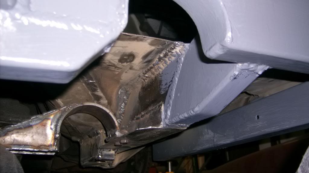
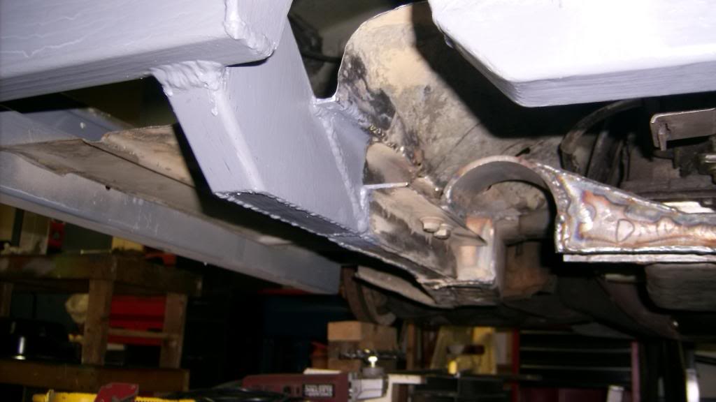
although this was plan "B" I think it came out pretty well. It definitely increased the torsional rigidity of the whole car. Even though there is no X brace the new design cuts up the cabin space into smaller rectangles and once the floor pans are welded in they will act as shear plates and give the rectangles a degree of diagonal support as well.
09-05-2015 #15
Registered User
- Join Date
- Jun 2015
- Location
- kent,ohio
- Posts
- 128
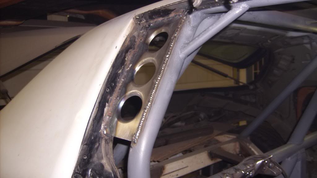
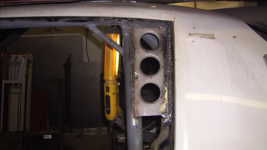
to tie the body to the cage I used 18ga sheet steel. for the wider gaps I used a dimple die to lighten and strengthen the panels. For the smaller gaps 1" strips were fitted between the body and cage. All pieces were completely stitch welded.


09-10-2015 #16
Registered User
- Join Date
- Jun 2015
- Location
- kent,ohio
- Posts
- 128
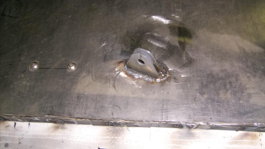
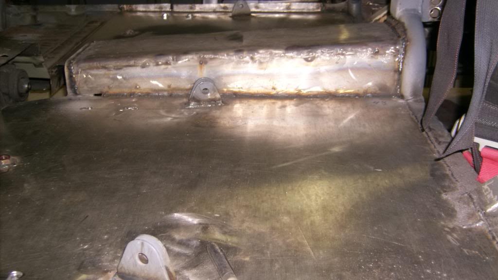
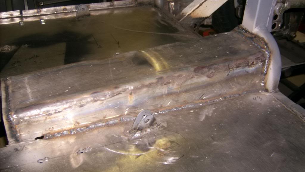
Time to put the floors back in. This is a budget build and metal is expensive so I use whatever will satisfy the need and not worry if it is a little heavier gauge metal or what type metal as long as i can weld it. The floor pans are made from 18ga food grade stainless (magnetic, like most late model exhaust). It came from a 10' x 30" food prep table.
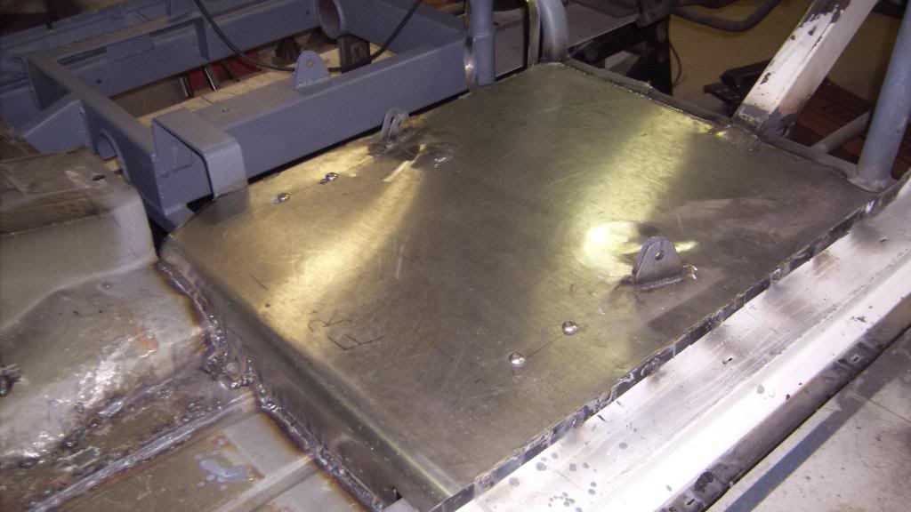
The table had a nice rounded edge that worked well to transition from the stock floor.
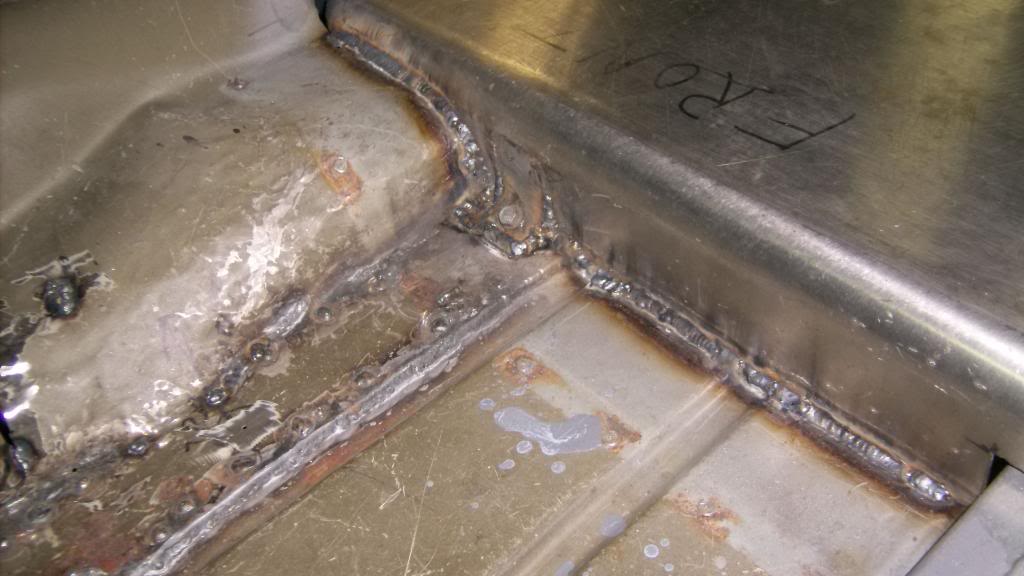
I bent a 90* lip at the door side and plug welded it to the pinch weld.
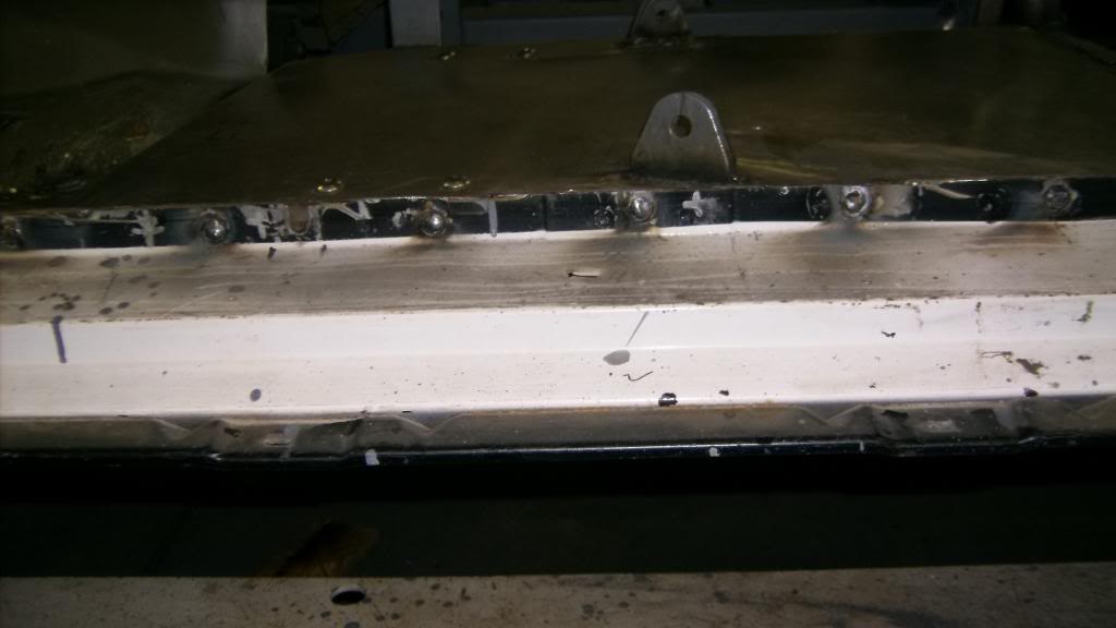
Floor pan was slotted for seat belt anchors to pass thru and then fully welded around them. pans ae completely stich welded front and rear and along the tunnel.

09-10-2015 #17
Registered User
- Join Date
- Jun 2015
- Location
- kent,ohio
- Posts
- 128
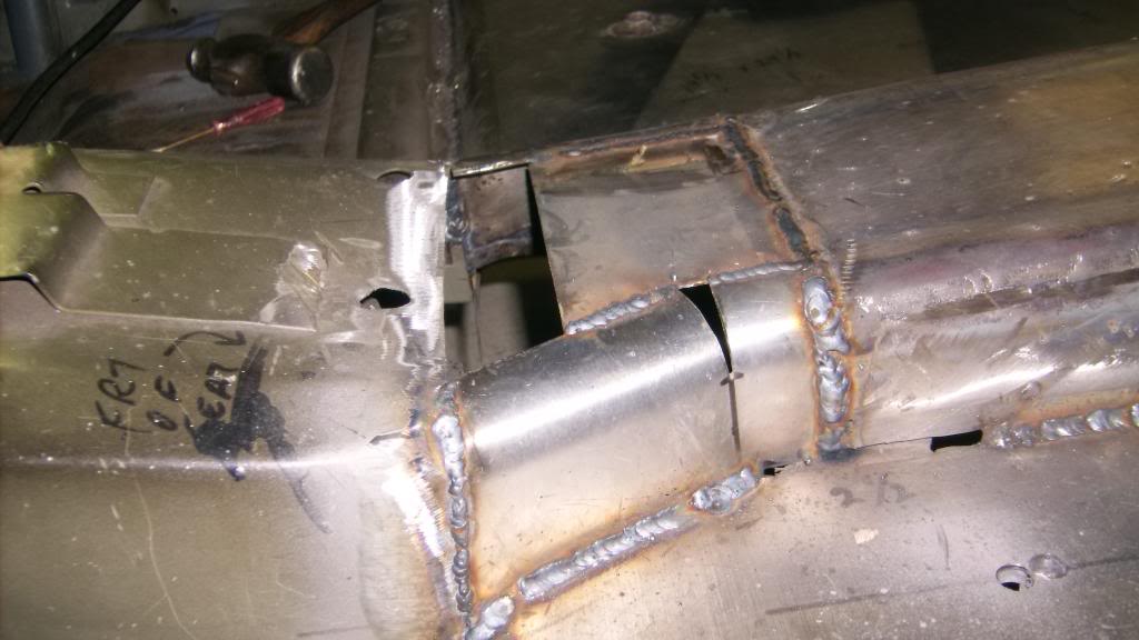
The trans tunnel was a bit more difficult because this stuff is really hard to bend. I was trying to make the corners rounded so bent the metal over a 1 1/4 pipe. Tried to keep it similar to stock transmission tunnel shape at front. Also note that since I did away with the OE torque arm I could make the tunnel about 2" narrower on the driver's side. I used the extra floor pan space to move the driver seat more toward the center of the car for a little better crash protection.

09-10-2015 #18
Registered User
- Join Date
- Jun 2015
- Location
- kent,ohio
- Posts
- 128
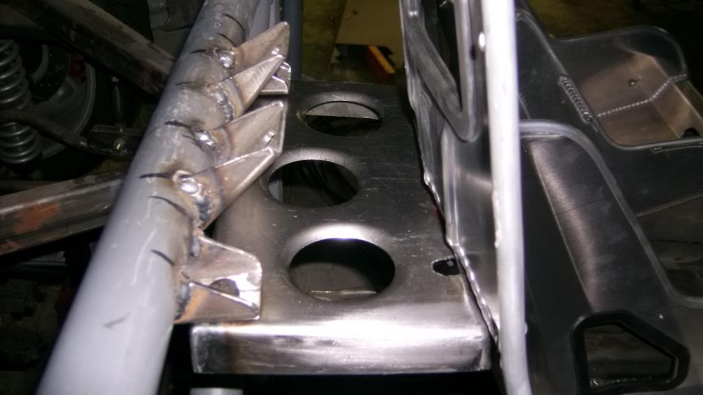
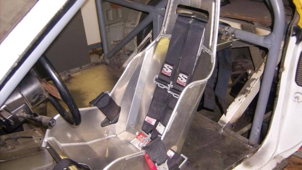
To mount the seats I made some floor brackets from the same stainless as the floor pans. They can be mover for and aft 3".
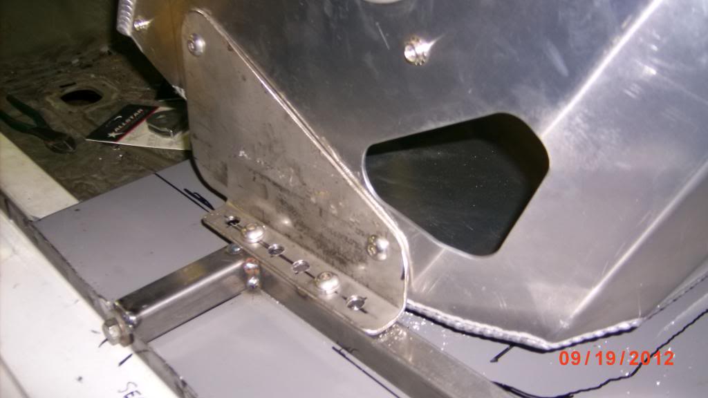
For the seat back and shoulder harness mounts I chopped up some 2x2 square tubing and made these brackets. The angled ones mount the shoulder straps and the horizontals mount the upper seat bracket.

The upper seat brackets were made from 18ga sheet.
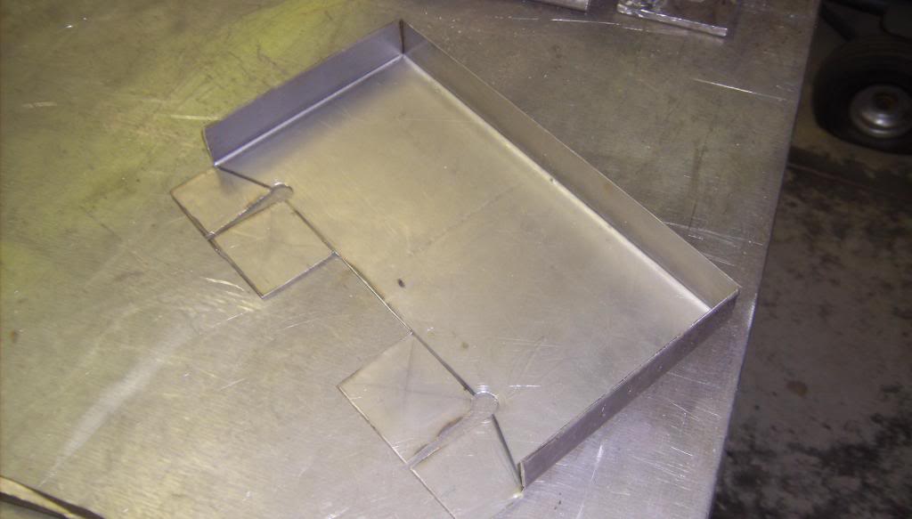
seats backs bolt to 4 tabs with 1/4" bolts.
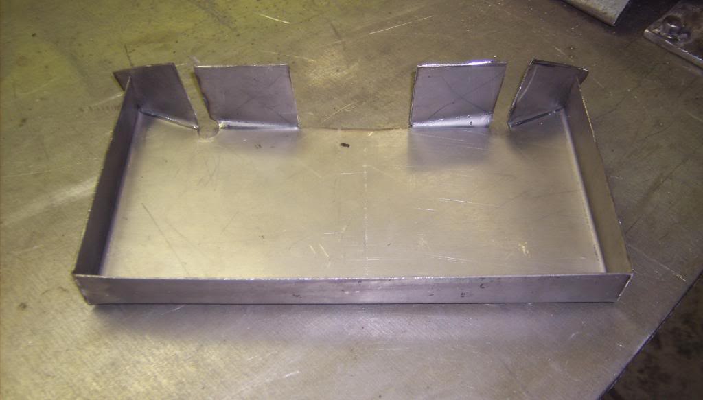
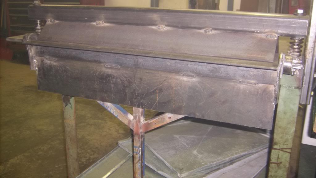
I bent these on my home made sheet metal brake. It will bend 18ga x 29" long and make 3 sides of a box.

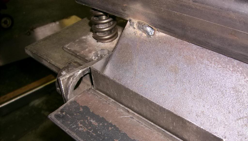
The corners were welded up and smoothed then punched with a dimple die to lighten and strengthen.
and with seat and belts mounted.

09-12-2015 #19
Registered User
- Join Date
- Jun 2015
- Location
- kent,ohio
- Posts
- 128
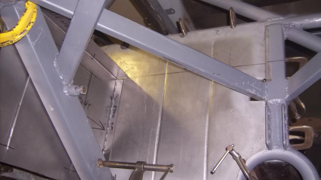
The passenger area stops at the main hoop of the roll cage so a rear firewall needed to be made. I elected to mount it flush to the rear side of the cage to make a smooth exterior wall with no ledges for water or roadwash to accumulate. All metal is 18ga.
I started by making poster board templates.

and one for the inner wheel well
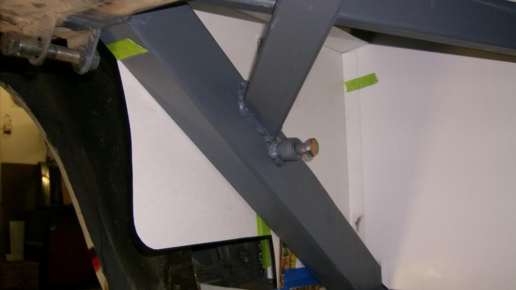
and in steel
driverside firewall

Inner wheel well
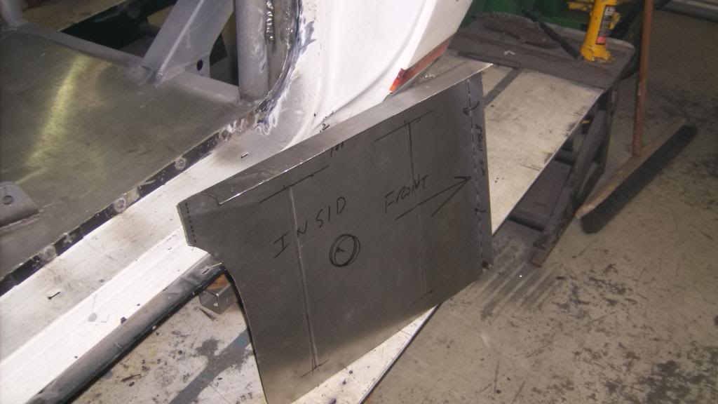
Together in car
09-12-2015 #20
Registered User
- Join Date
- Jun 2015
- Location
- kent,ohio
- Posts
- 128
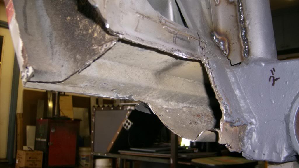
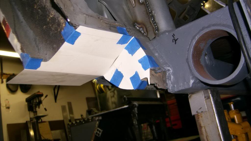
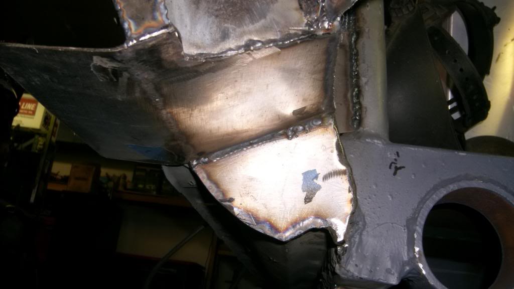
Before I could go further I had to cut out the rocker panel for the side exit exhaust.
Templates to box in rocker.
and in steel.
with exhaust pipe
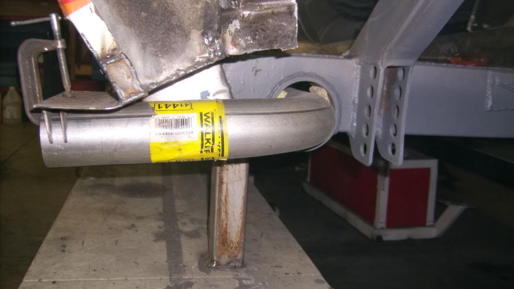

I will have to make a fancy tip once the gfx are reinstalled.


 Reply With Quote





