

Results 41 to 60 of 63
Thread: 1971 Speedipus Rex
-
05-16-2014 #41

 Registered User
- Join Date
- Mar 2008
- Location
- Brisbane Australia
- Posts
- 410

Your attention to detail is amazing, great to see another mopar being built for handling too
Hot rodder's recycle, wheres those prius' going when the tree huggers have a new fad.
-
05-17-2014 #42 Registered User
- Join Date
- Mar 2012
- Location
- Lethbridge, AB
- Posts
- 177

 Originally Posted by 19,69camaro
 thanks guys ! just trying to build my dream car Originally Posted by linkstar69

there's one or two things I would have done different but not much.Build Thread!!!https://www.pro-touring.com/showthread.php?88692-1971-Speedipus-Rex&p=925864&posted=1#post925864
05-17-2014 #43
Registered User
- Join Date
- Mar 2012
- Location
- Lethbridge, AB
- Posts
- 177
It's nothing to look at right now, mostly apart, but its a cool project - 340 auto, petty blue, tombstone front bench, fold down rear seat Originally Posted by instro84
Build Thread!!!https://www.pro-touring.com/showthread.php?88692-1971-Speedipus-Rex&p=925864&posted=1#post925864
09-18-2014 #44
Registered User
- Join Date
- Mar 2012
- Location
- Lethbridge, AB
- Posts
- 177
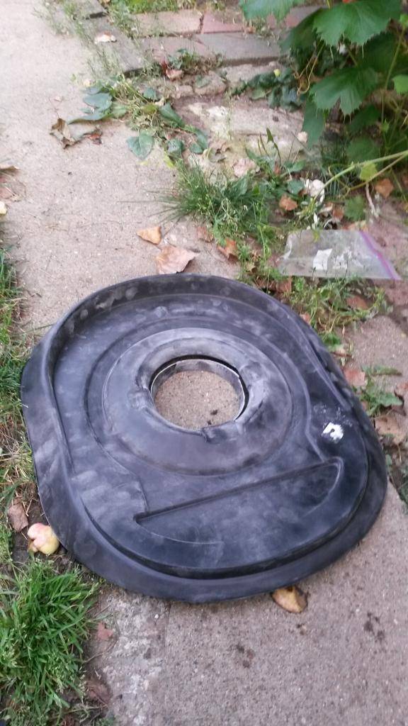
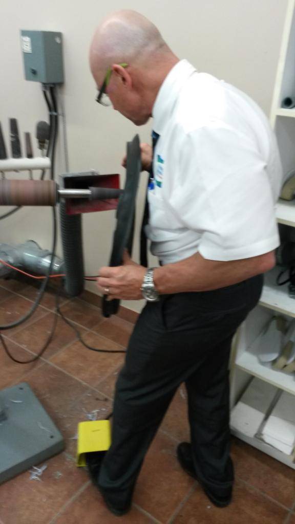
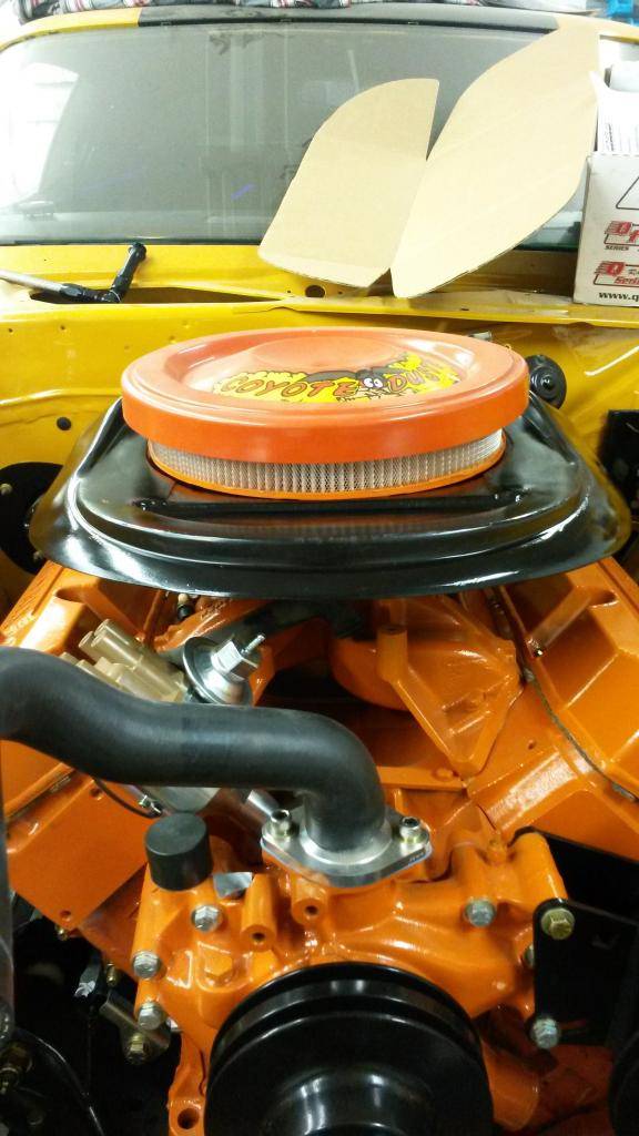
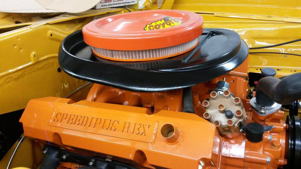
Sorry for the long wait guys, I have 5 things on the go and was waiting for it all to be finished before I post them - here' s one project that I recently finished: A airgrabber on a RPM intake that actually fits under the hood, another guy tried this on roadrunnernest.com where he cut just enough and cheat it slightly but the hood really pressed down on the intake, I wanted something that was a perfect fit, I bought this base from YearOne, its a cheap fiberglass base that you don't have to worry about cutting into it, and it feels significantly lighter compared to the steel OEM base! I may weight it later to see the weight savings...
cut the hole i wanted - wanted to get it as low as possible so I have no issues:
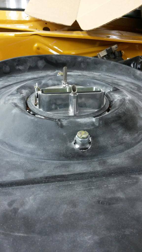
My QFT carb has two screws on the car that were preventing it from going lower, the nuts are just the size i need to putty over

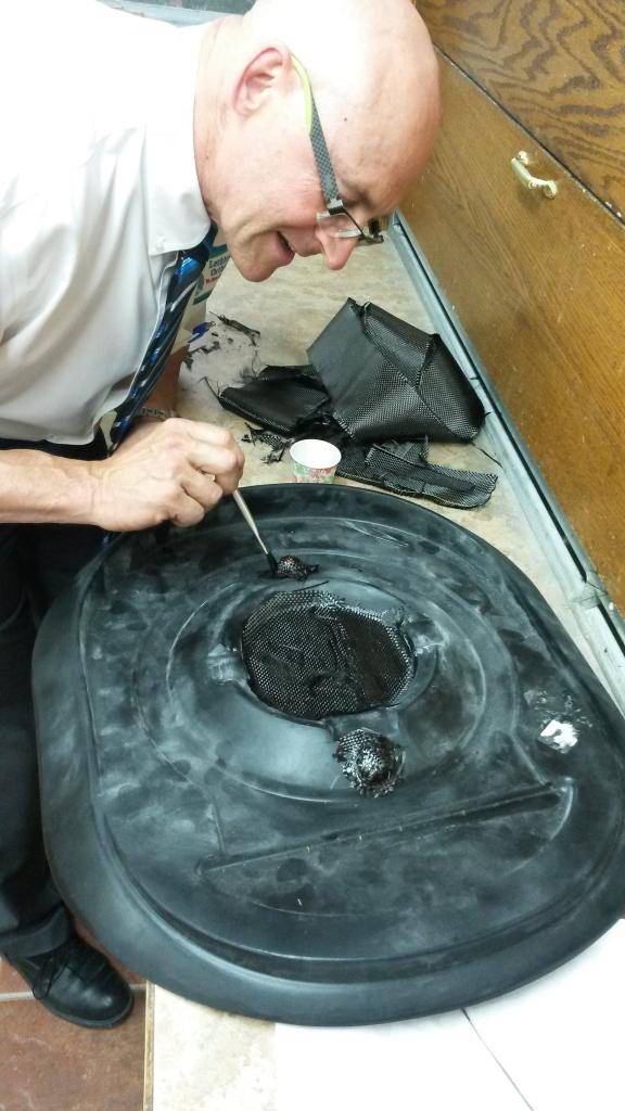
my dad teaching me how to work with carbon fiber
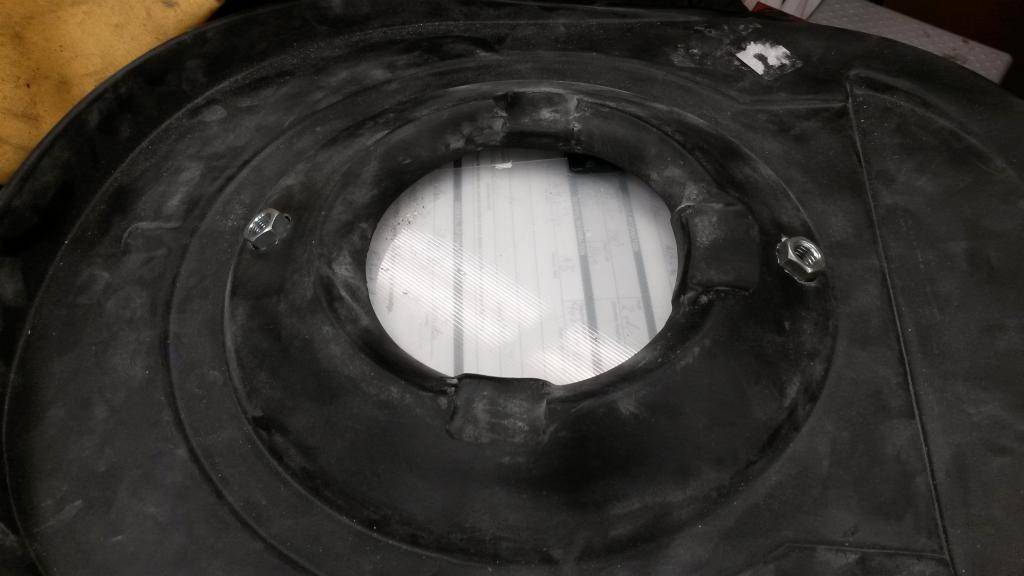
Use the piece I cut off to trace out the size of the hole
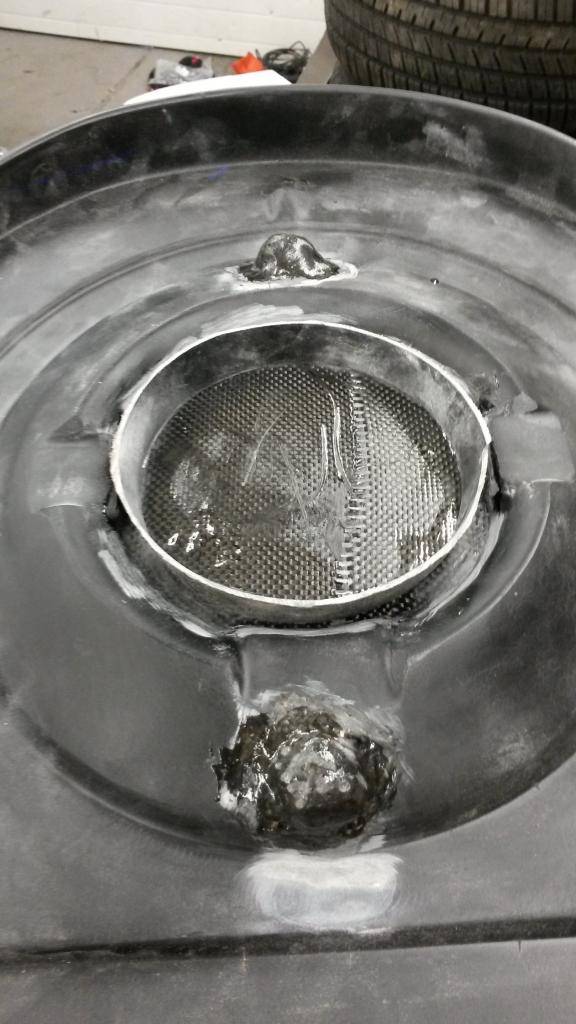
slowly sand to where I want it

sand, paint, put her on - a perfect fit!!
More stuff to come!Build Thread!!!https://www.pro-touring.com/showthread.php?88692-1971-Speedipus-Rex&p=925864&posted=1#post925864
09-19-2014 #45 Registered User
- Join Date
- Dec 2006
- Location
- Barrie, Ontario, Canada
- Posts
- 108
Looking great!
Used to be known as 455regal
09-24-2014 #46
Registered User
- Join Date
- Mar 2012
- Location
- Lethbridge, AB
- Posts
- 177
Next on the list is my custom hub and steering wheel setup - I got sick and tired trying to find a aftermarket hub for our bbodies so I decided to get one made. I like the bigger grips of the aftermarket wheels available for my big mits. I bought this hub, its for an ebody (what a heavy beast) but it gave me enough matierial to shave off what I needed.
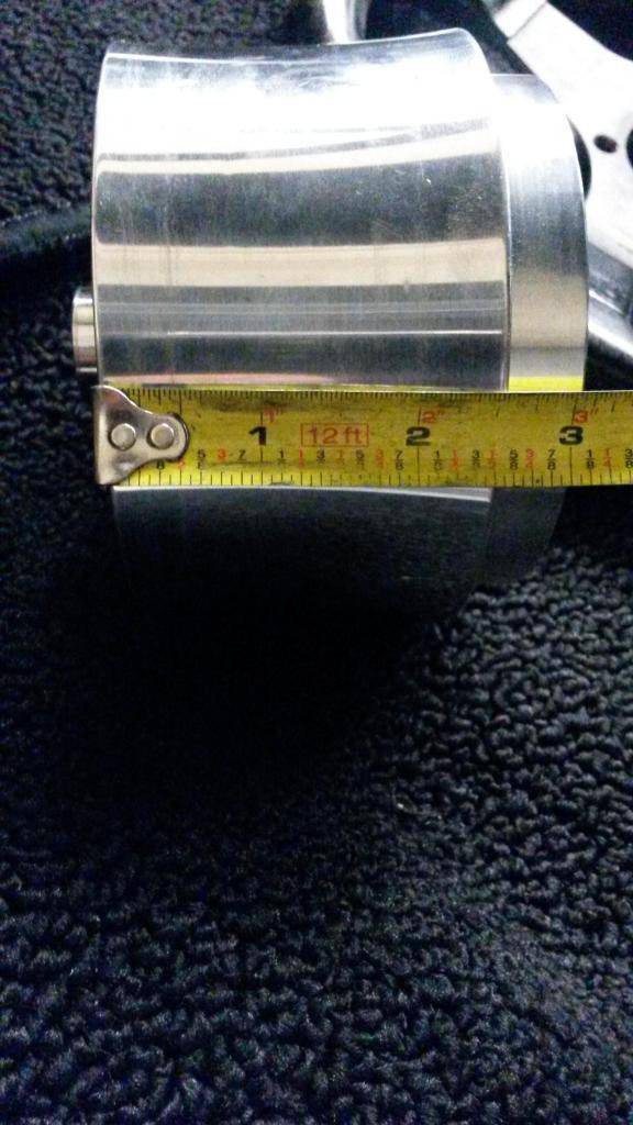
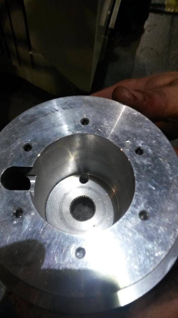
I had a machine shop shave it down to this:
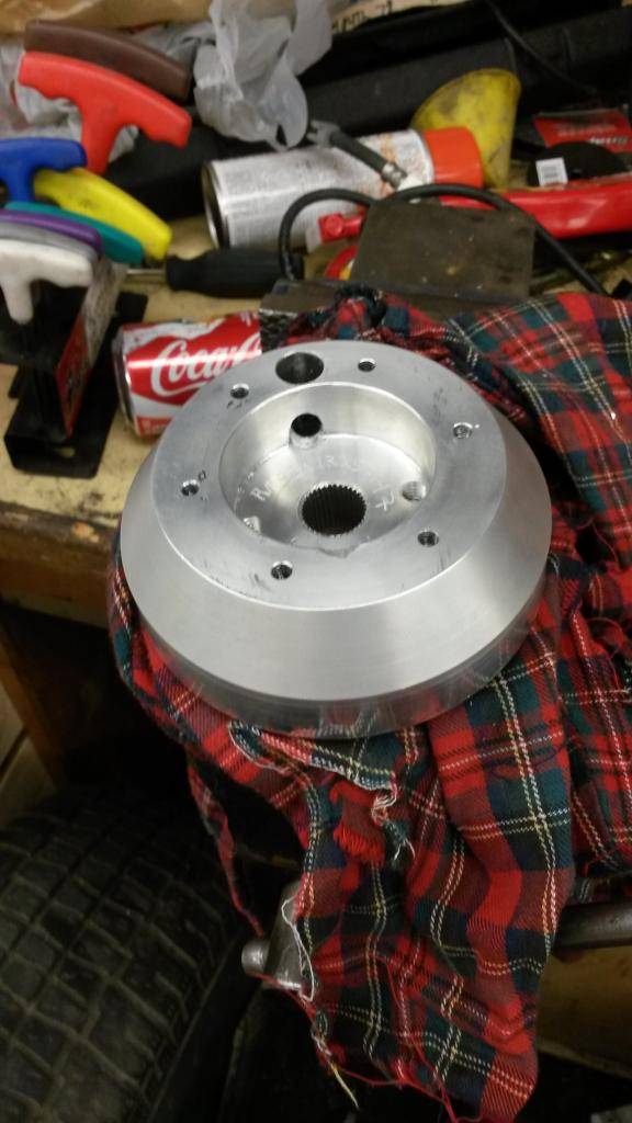
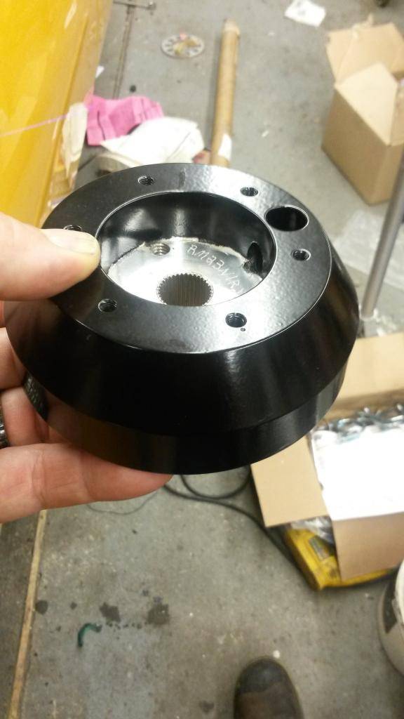
got it powdercoated black
old height stock wheel 5 3/8" deep
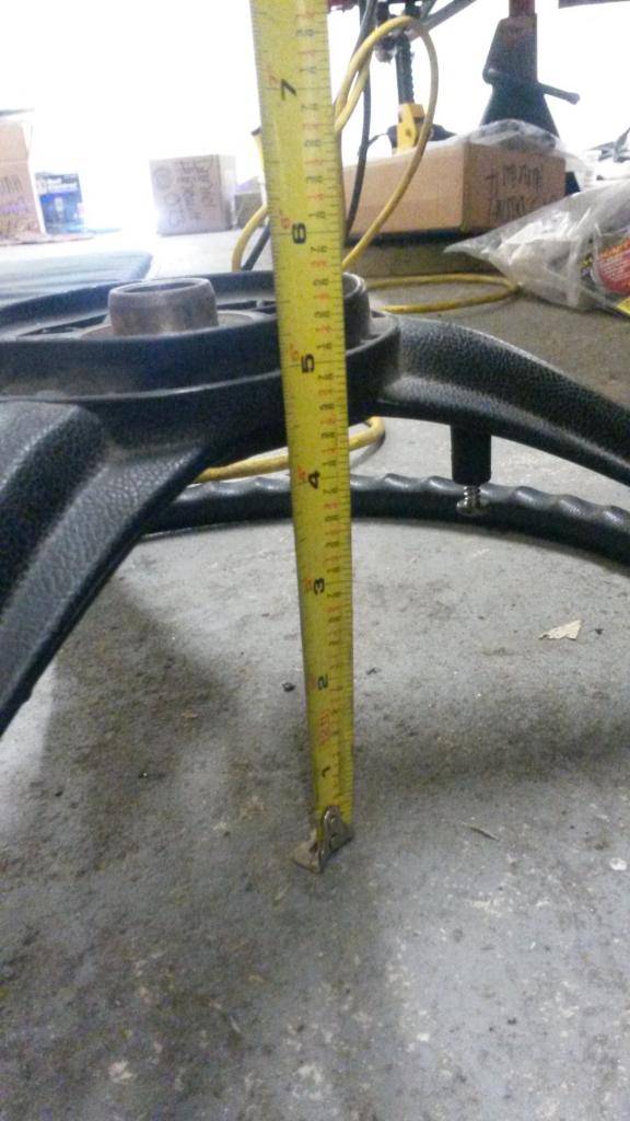
new height with MOMO steering wheel 3 1/8" deep
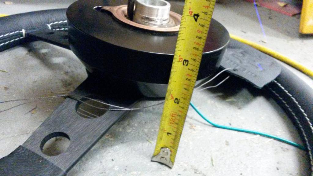
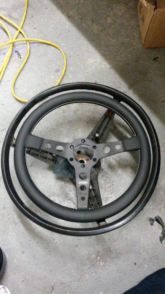
New 350mm MOMO wheel compared to the stock OEM one
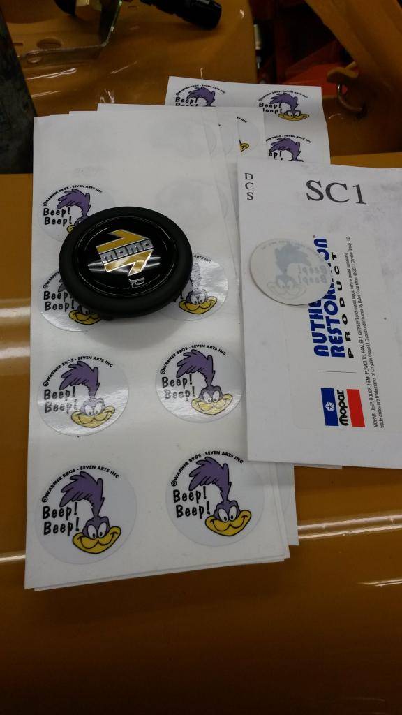
I bought a 1970 steering wheel decal and was hoping it would be big enough to fit the whole MOMO button and it did, what I didn't know is about the 1970 decal is that the sticky side is on the picture side not the back side, so I took it to a local decal shop and got some made:
sanded the MOMO button (it has raised lettering, I sanded it down with wet sand paper until she was flat):
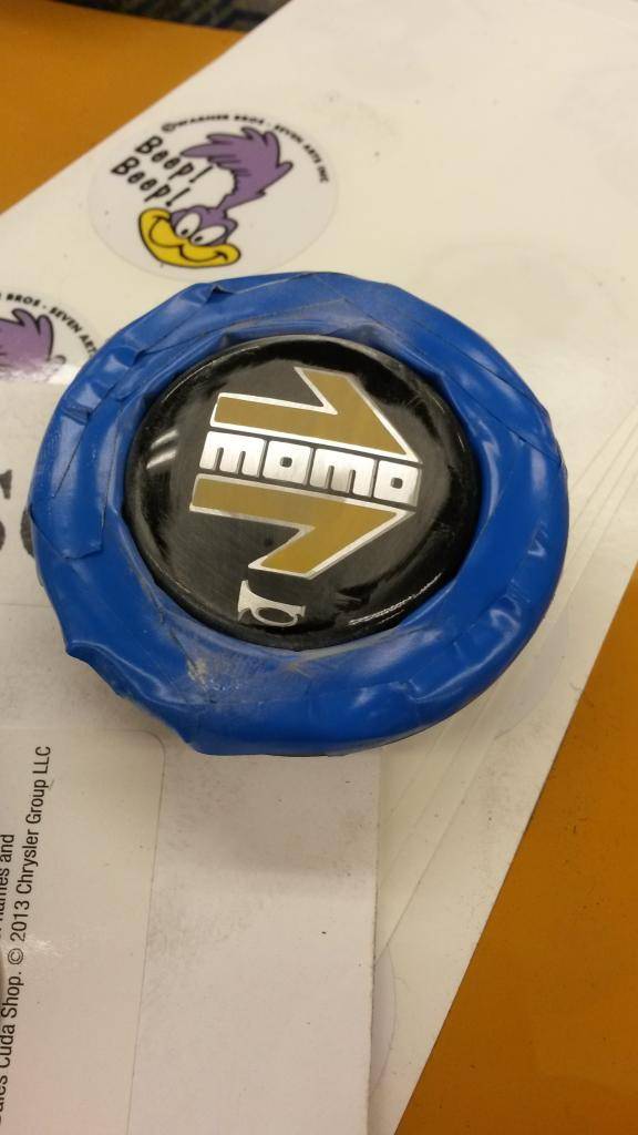

TA-DA! The end result!

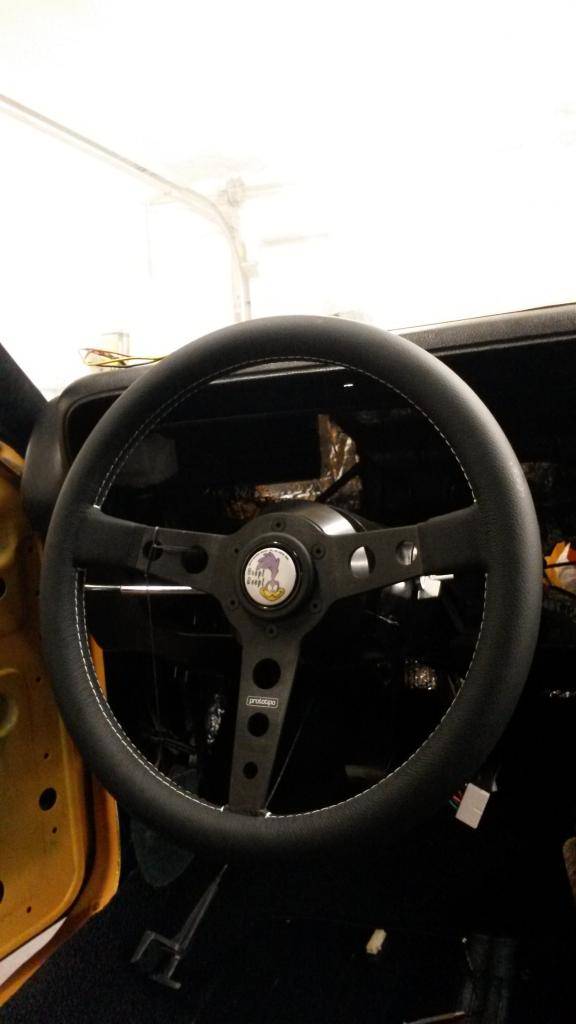
I also should note that I had to bend the flasher more straight so it wouldn't interfere with the new wheel setup!Build Thread!!!https://www.pro-touring.com/showthread.php?88692-1971-Speedipus-Rex&p=925864&posted=1#post925864
09-25-2014 #47
Registered User
- Join Date
- Mar 2008
- Location
- Brisbane Australia
- Posts
- 410
Nice work
Hot rodder's recycle, wheres those prius' going when the tree huggers have a new fad.
11-06-2014 #48
Registered User
- Join Date
- Mar 2012
- Location
- Lethbridge, AB
- Posts
- 177
so I work 12hr days 4 on 4 off 4 nights 4 off. But the past month and for the next 2 months I have been working 2-3-even 4 of my days off trying to save up so we can build our dream house, and dad gets the shop he's always wanted. Needless to say I haven't been working on the car, but I have finally uploaded most of the pics I have, sadly I lost alot of good pics somewhere, I need to have this car finished by spring, correction, I HAVE to finish this car by spring or it'll never get done if were building a house. Im close but still oh so far...
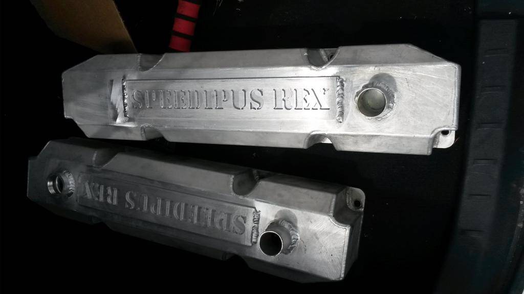
bought blank aluminum valve covers and had my buddy tig weld the plates on he cut from his small home cnc machine:
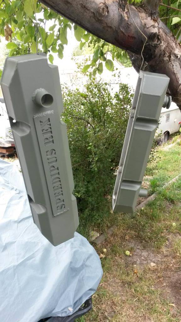

painted the front of my rad support with plastidip, just in case if i didn't like it, i could always peel it off
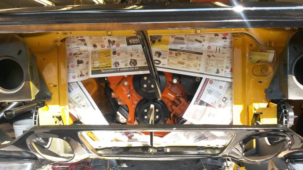

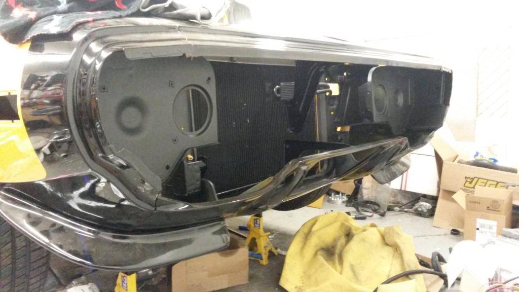
Didn't like the look of a huge aluminum square in the front of my car so I painted it black, I've read alot of circle track guys do this anyways so I don't see the harm:

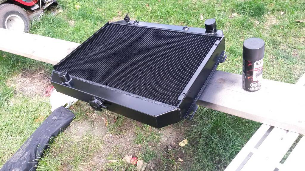
installed!
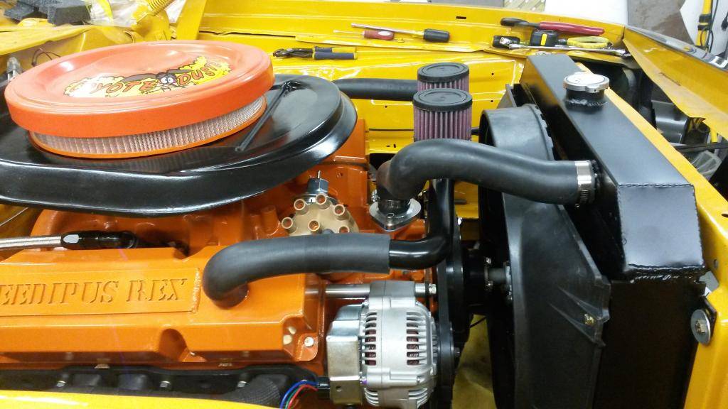
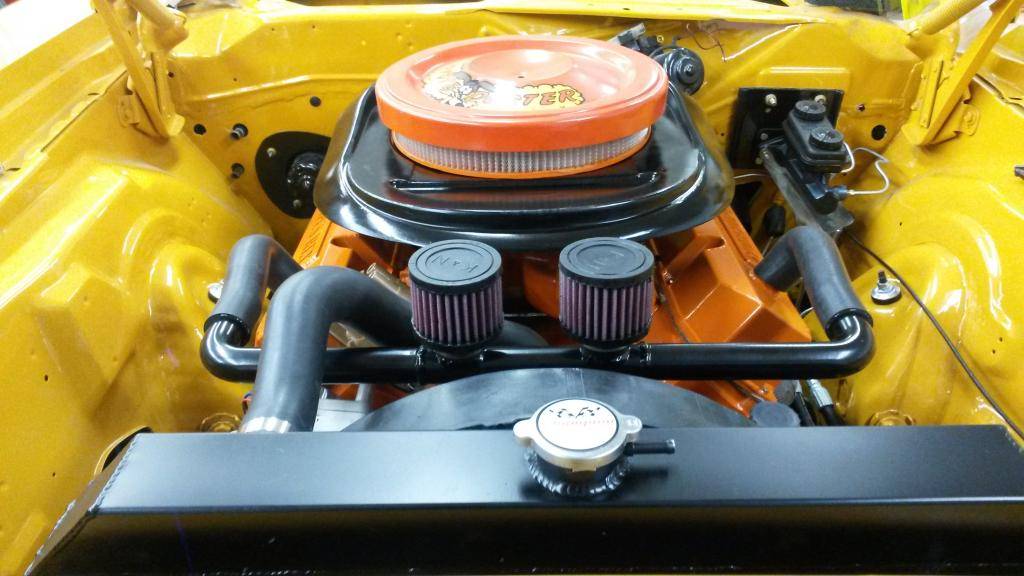
So AutoX cuda inspired me to do a similar setup for my breathers, like the old trams am racers, I bought aluminum 1 1/4" tubing (sorry not sure were the photos went) and 1 1/4" aluminum 90 degree bends, two 1 1/4" K&N breathers, and 2 goodyear 1 1/4" rad hoses Part #60083, had my buddy weld it up the lips on the valve covers to mount them, and weld up the pipes. Got it powder coated black, I think it looks really good! It also clears the airgrabber setup on my hood:

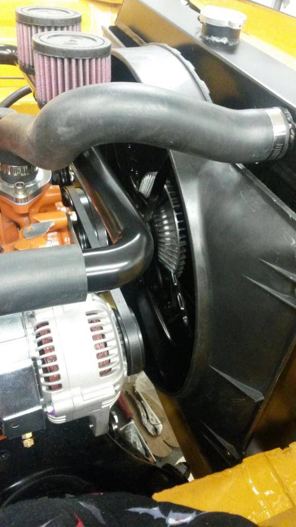
got tired of waiting for my MP viscous fan setup so I went to the yard and bought this fan from a 90 dodge truck with a 318

got it powdercoated, new clutch and fan shroud and installed
bought a new heatercore (it was bugging me that it was the only thing that hasn't been replaced) to my surprise (not really) it was no where near where I needed it mounted so I had to resolder the mounting plate

I didn't like the fact that the only option for a torque strap out there was a $100 option, So I made this for les than $10, grade 8 fine thread rod, 3/8" heim link and the washers/bushings from my prothane kit that were suppose to be for a stock sway bar, but seeing how I'm running the bigger Hellwig's, they were perfect!
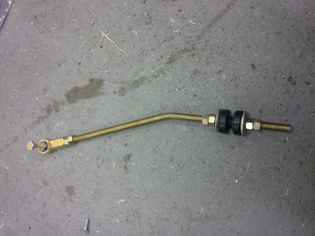
my almost 2 year old son decided that he wanted to install it!

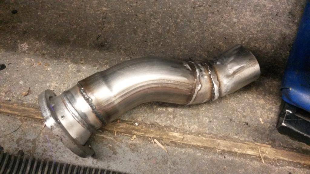
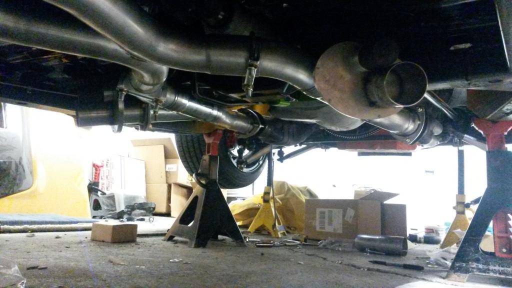
I installed the TTI exhaust with the dougs cuttouts, fit pretty good, the only thing I had to modify was the pipe from on the passenger side from header to cutout:
 Build Thread!!!https://www.pro-touring.com/showthread.php?88692-1971-Speedipus-Rex&p=925864&posted=1#post925864
11-06-2014 #49
Registered User
- Join Date
- Mar 2012
- Location
- Lethbridge, AB
- Posts
- 177
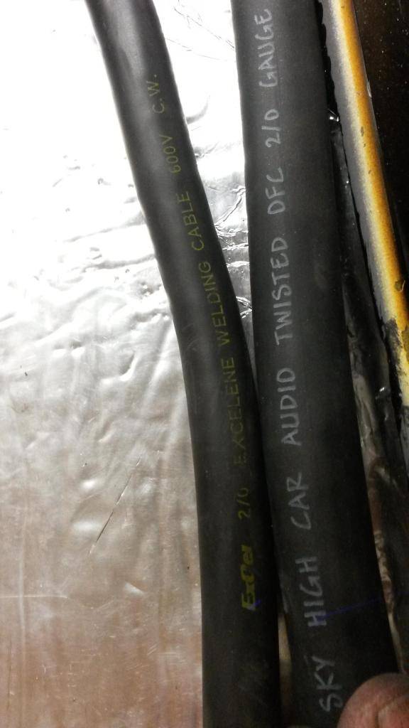
I bought some premium 2/0 cable for my battery relocation, I wanted 1/0 but this is what my buddy had, he's in the custom stereo business and even at his price it was $7.50 a foot, but as big as this stuff is, you can bend it around your wrist, its that flexible! And the amp draw you can pull on this stuff makes welding cable look like yesterdays knob and tube. This pic is the comparison of the two.
I bought 3/4" wheel spacer adapters for all for corners, premium quality all made with grade 10 bolts, the reason behind this was
1) To clear the long hub on the front of the car for my wheels
2) widen the track as much as possible
Since I'll be running the Enkei RPF1 18X9.5" +15mm on all 4 corners these will push those wheels out as far as I'd like to go. Now that I have the wheels I could have went with the 18X10.5" +15mm but I would have to extend the wheel studs and use a 10mm spacer. So for now I'm gonna use these rims and do the bigger rims down the road.
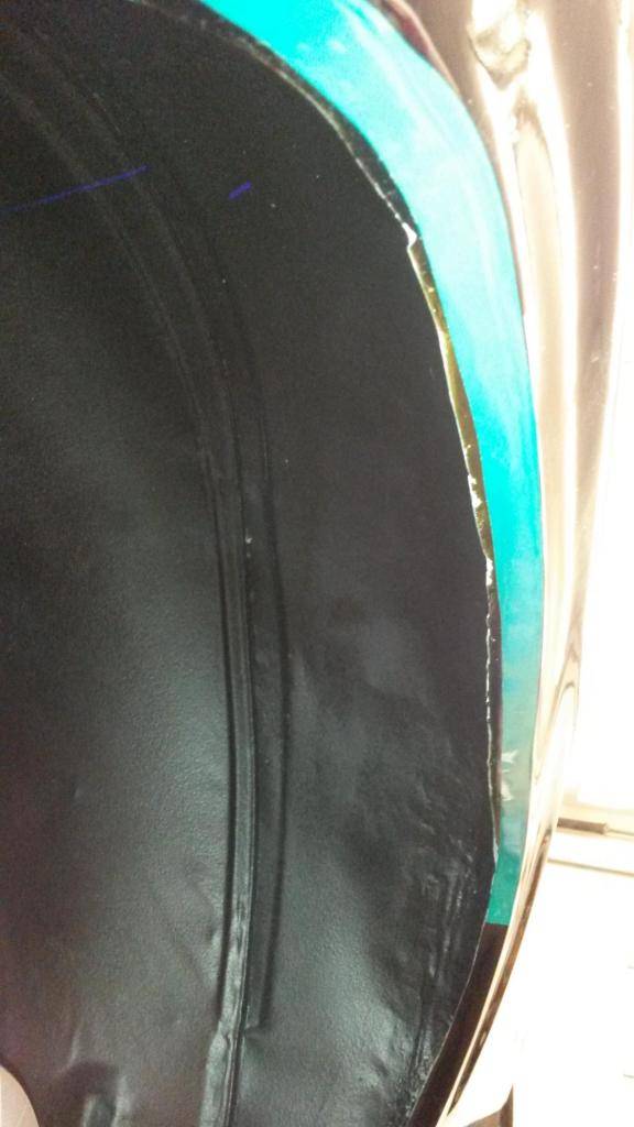
I am a little bit too close for comfort in the rear so I have shaved the inner lip as much as I possibly could to get more clearance, as you can see it was never a straight line to begin with, I gained as much as 3/8" in some areas and as little as 1/8." overall I have about 1/2" clearance from the tire to the inner lip, I'll get more pics on that later:
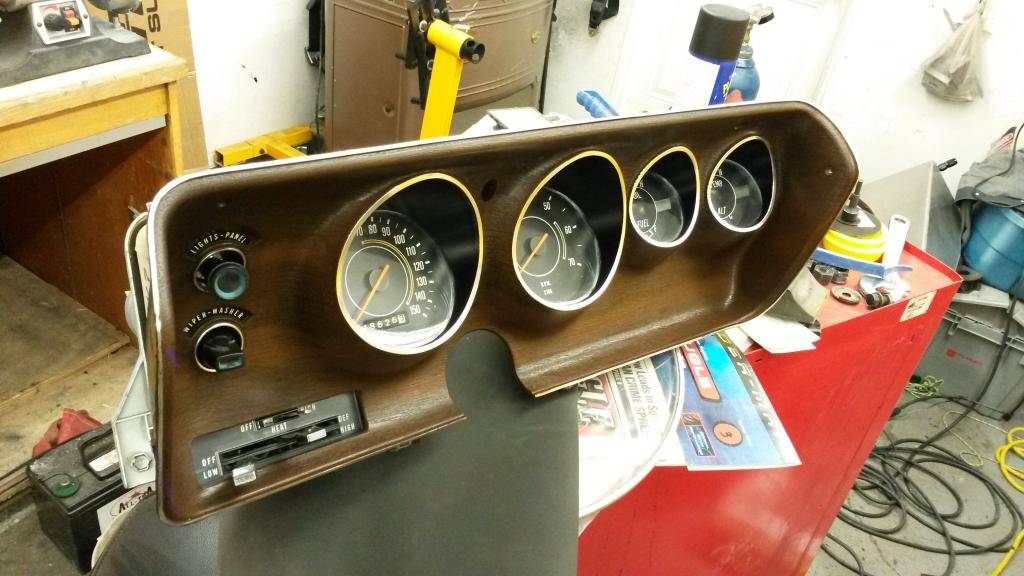
Last but not least I finally got my hands on a radio delete bezel!!!!! and a tach option dash as well!!!! (paid way to much for them) This is so cool I just wanna mount it on my wall! I restored the guages like I did with my other bezel, used my 150 mph speedo, cleaned it all up nice, I may do a layer of clearcoat on the bezel, haven't decided yet...

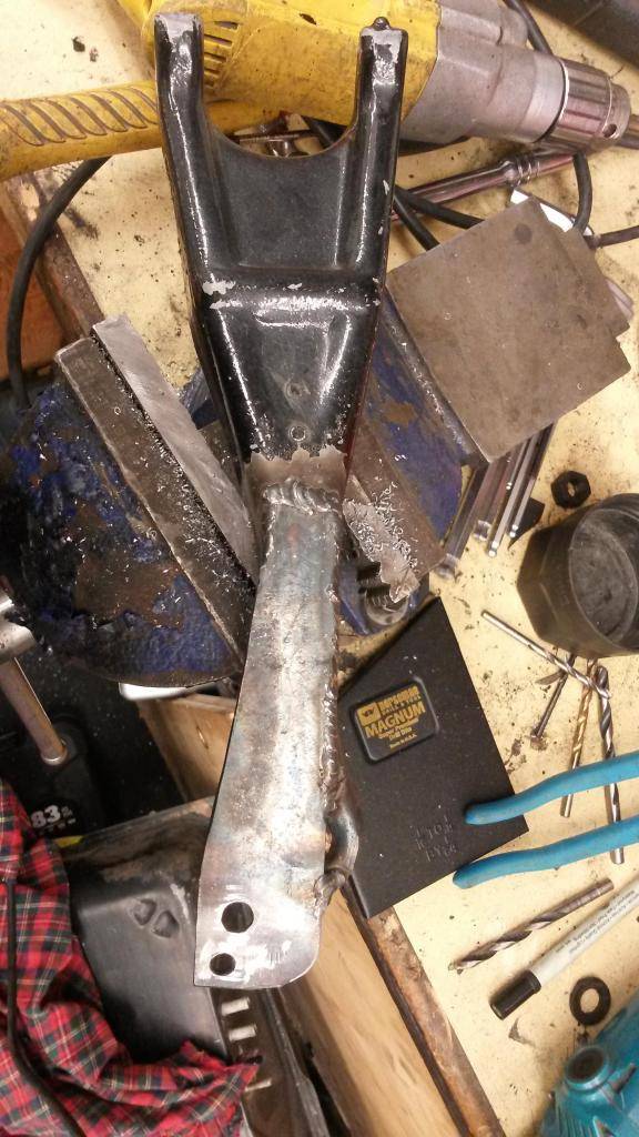
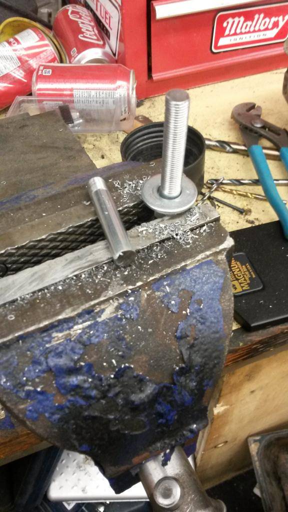
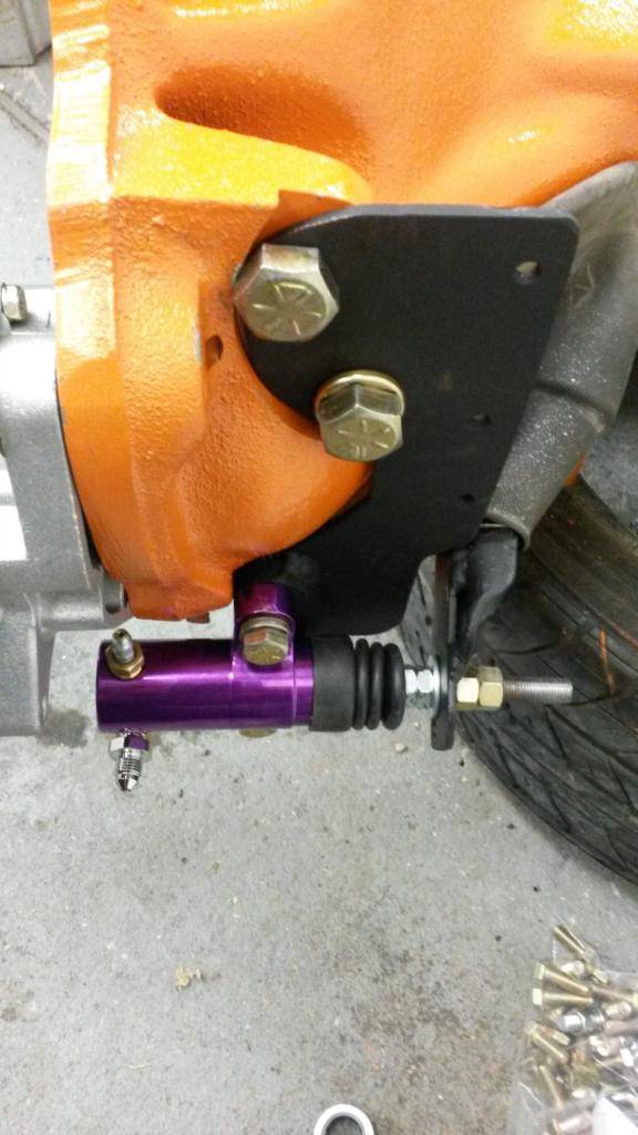
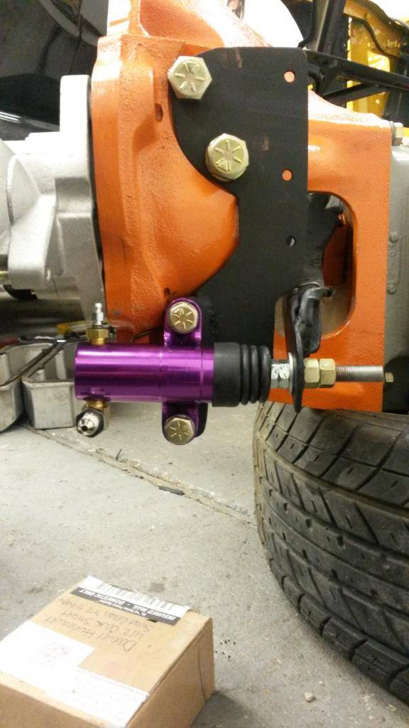
finished my custom slave cylinder, Had to put two clearance dents on the header but other than that I think this should work awsome! I could not for the life of me drill any holes in the clutch fork(must be made up of adamantium) So I had to weld on the extend plate for the clutch (i wanted to have it bolt on originally), tapped the push rod all the way, heres what I got so far:

So that's kinda where I'm at at the moment
Build Thread!!!https://www.pro-touring.com/showthread.php?88692-1971-Speedipus-Rex&p=925864&posted=1#post925864
11-07-2014 #50 Registered User
- Join Date
- Nov 2009
- Posts
- 169
Great project! Keep updating!!!!!!!
64 Mercury Comet
408w boosted
More boost on the way!
02-18-2015 #51
Registered User
- Join Date
- Mar 2012
- Location
- Lethbridge, AB
- Posts
- 177
Work has finally slowed down and I'm focusing now on the wiring, problem is I'm running all brand new wiring as my old wiring is either chopped, cut, *******ized or just missing. Problem is a lot of the new wiring is same but not the same. To help identify the wiring I'm currently making a picture wiring manual for future users who don't want to spend hours like I'm doing, trying to figure out where everything goes. I've spent some time doing this - hope it helps those down the road.
DONOT FORGET TO USE DIELECTRIC GREASE OR CRC 2-26 SPRAY FOR YOUR ELECTRICAL CONNECTIONS, ESPECIALLY FOR THE BULKHEAD CONNECTORS!!!
***update (1) had to switch the brown and red wire leads on the windshield wiper motor harness as they were backwards when plugged into the bulkhead***
***update (2) M&H for some reason moved the horn wiring from the lamp harness to the engine harness, and they moved the low brake switch wiring from the engine harness to the lamp harness. So if one wanted to run a mix of old harnesses and new, you would have to change these wires in the actual harness themselves to get it to work.***
Now let's begin:
Main Dash Harness for 1971 Plymouth / Dodge Bbody With Rallye Dash (M&H Electric / YO):
(pic1)
(pic2)
(pic3)
1) 2 wires, both dark blue with yellow stripes
A) headlamp washer, whatever accessory on the car - rear deffog, powered trunk latch, A/C clutch source
B) This was used for more than one option, youget in fact those feeds full in 71, a bit less in 72. 73/74s got less accessories options and they got just one mold instead two on Harness. All extra stuff to be plugged on those molds USUALLY match the color of the molds on harness. You can see it on the A/C clutch feed of the pic 50, male is molded in yellow same as the harness mold... its a 20 amps fused source BTW
(pic4)
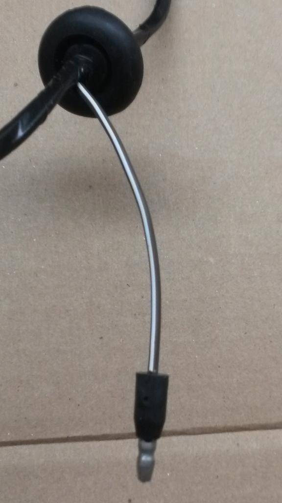
1) brown wire with white stripe
A) headlamp washer
B) The rubber grommet goes into the hole, through the fire wall, its the upper hole near the master cylinder (or booster)
(pic5)
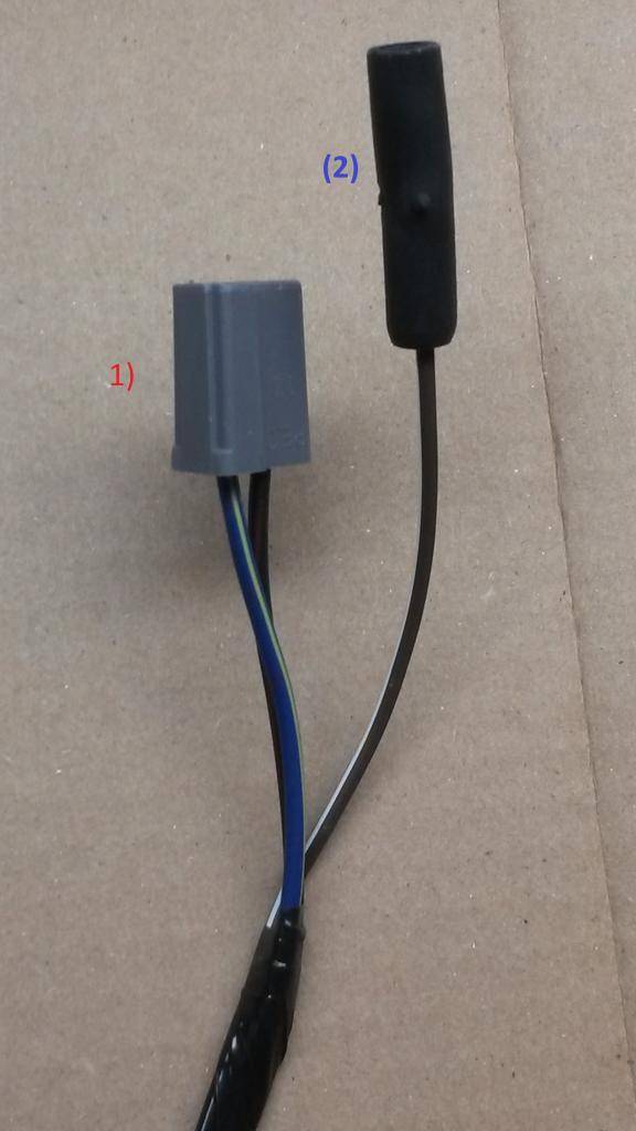
1) dark blue wire with yellow stripe, black wire with red stripe
A) concealed headlamps
B) for dodge chargers not used on GTX/Roadrunner/Satellite
2) Other side of brown wire with white stripe
A) headlamp washer
B) engine side for headlamp washer
(pic6)
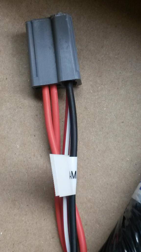
1) 2 solid orange wires, one red wire with white stripe, solid black wire
A) AM Radio
b) Radio Harness
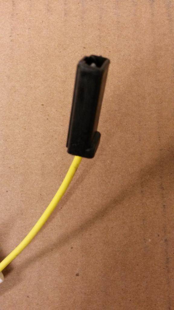
(pic7)

1) solid tan wires to 3 port yellow female connector
A) accessory feed
B) ?
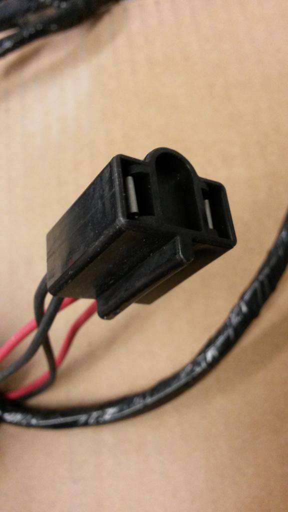
(pic8)
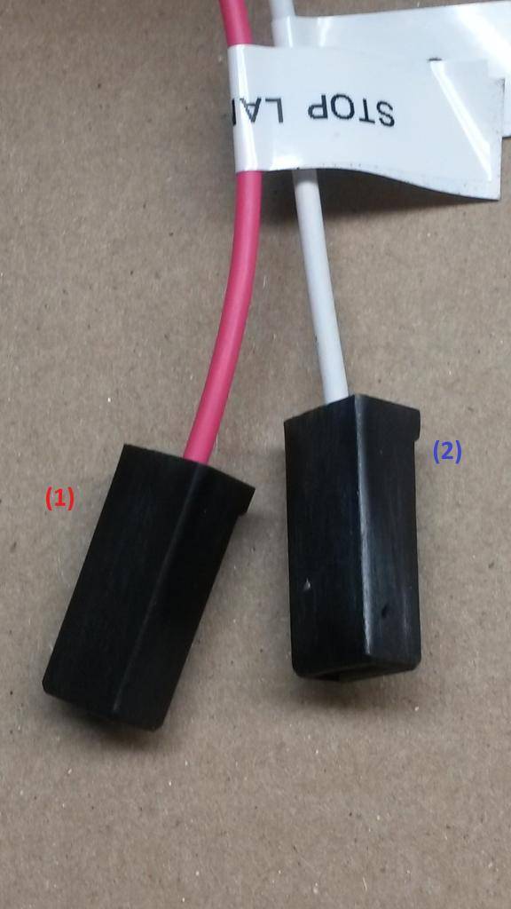
1) solid pink wire
A) stop lamp switch
B) switch on brake pedal
2) solid white wire
A) stop lamp switch
B) switch on brake pedal
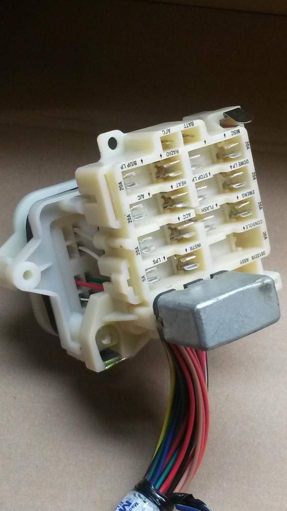
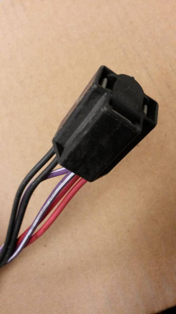
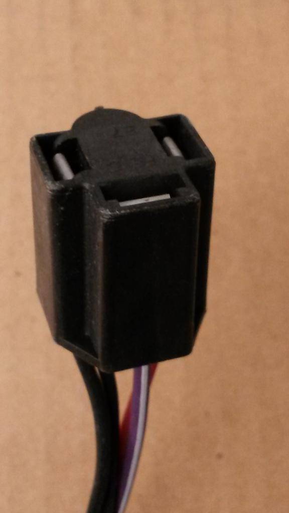
(pic9)
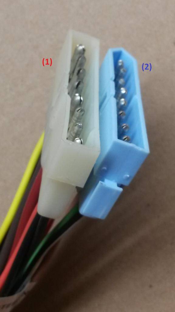
1) solid yellow wire, solid black wire, blue wire with white stripe, solid brown wire, solid red wire, solid orange wire, solid black wire, solid black wire
A) steering column
B) steering column harness
2) black wire white stripe, solid light green wire, solid tan wire, solid pink wire, solid red wire, solid dark green wire, solid brown wire, solid white wire
A) steering column
B) steering column harness
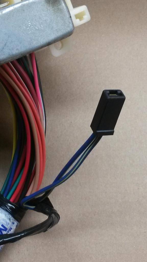
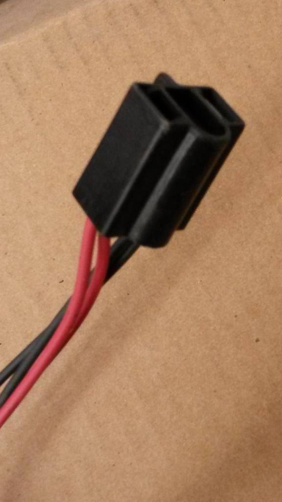
(pic10)
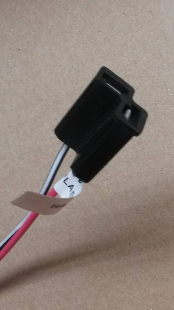
(pic10a)
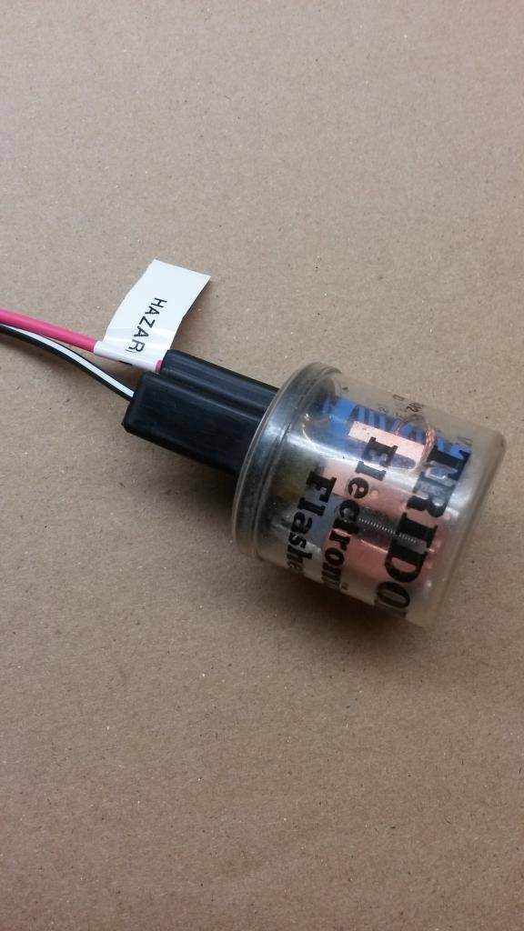
1) solid pink wire, black wire with white stripe
A) hazard flasher
B) electronic flasher
(pic 11)

1) 2 solid black wires, 2 black wires with yellow stripe
A) headlamp-on warning buzzard
B) harness gets an extra pigtail to reach the buzzer mounted on dash frame between glovebox and ashtray. Buzzer gets a plug like the blinker flashers ones.
2) 2 yellow wires with black stripes
A) to ignition switch lamp time delay relay wiring
B) It is used for the little lite that shines from the steering column to the ignition key hole when the door is opened.
(pic12)
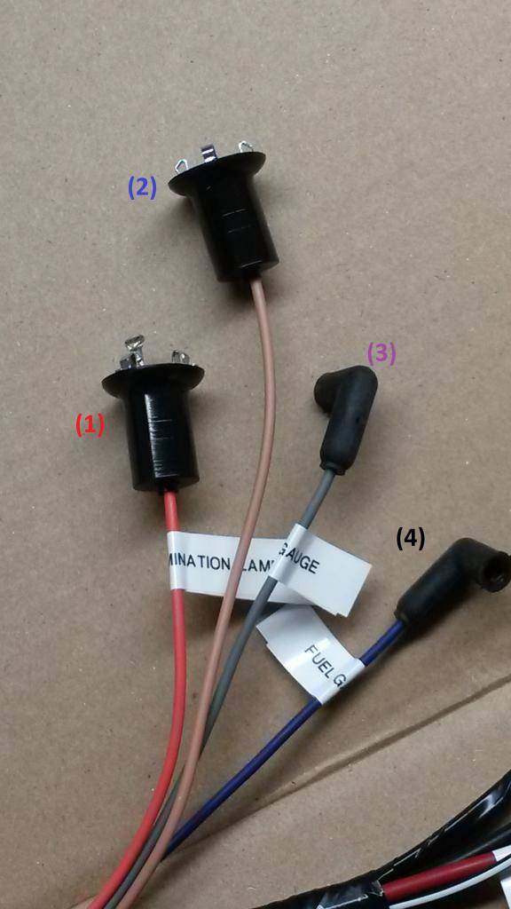
1) solid orange wire
A) cluster illumination lamp
B) back of rallye dash
2) solid tan wire
A) right turn signal indicator lamp
B) back of rallye dash
3) solid grey wire
A) oil gauge
B) back of rallye dash
4) solid dark blue wire
A) fuel gauge
B) back of rallye dash
(pic13)
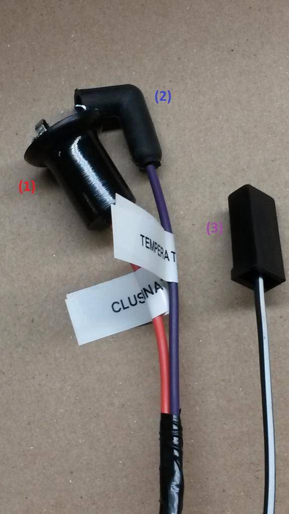
1) solid orange wire
A) cluster illumination lamp
B) back of rallye dash
2) solid violet wire
A) temperature gauge
B) back of rallye dash
3) black wire with white stripe
A) instrument cluster ground
B) voltage limiter have three prongs on back light face ( dunno if call it front or back LOL, because on standard cluster they are used backwards LOL )... two of them are actually an U shaped sheet. These two get the POSITIVE SOURCE from harness and the condenser noise suppressor which is attached with a phillips screw on back of cluster.. 3rd prong is the 5 volts output for gauges... it gets a small pigtail which sources all the gauges on the black wire.
The black wire with white stripe SHOULD be a wider terminal to be plugged onto the prong ( and bracket at the same time ) welded to voltage limiter "back case". This is made intentionally to NOT BE ABLE TO ATTACH by mistake the positive wire from harness on it ( would get a short as soon you put the key in RUN or ACC with this connected wrong ), since the prong on limiter case is also wider, matching the ground source plug
***UPDATE (3) I had to rob the bigger black connector off of my old harness because M&H uses a smaller connector and it won't fit on the voltage limiter prong (easy to do, use a flat head precision screwdriver and go through the front of the connector - the opposite end the wire goes into - and slide the screwdriver between the plastic housing and the metal connector) pic13a shows the wire on the old connector and the new smaller one I pulled off the harness beside it***
(pic13a)

(pic14)
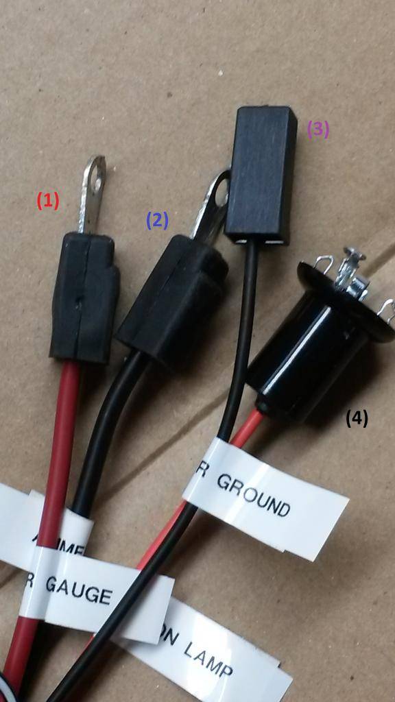
1) solid red wire
A) ammeter gauge
B) back of rallye dash
2) solid black wire
A) ammeter gauge
B) back of rallye dash
3) solid black wire
A) POSITIVE source for voltage limiter
B) plugs straight to voltage limiter double prong
4) solid orange wire
A) cluster illumination lamp
B) back of rallye dash
(pic15)


1) solid red wire, solid black wire
A) turn signal flasher
B) electronic flasher
(pic16)

1) solid green wire
A) concealed headlamp relay
B) be sure to tape over the ring terminals or cut them out completely
2) 2 dark blue wires with white stripe
A) concealed headlamp relay
B) be sure to tape over the ring terminals or cut them out completely
3) dark blue wire with yellow stripe, black wire with red stripe
A) concealed headlamps
B) for dodge chargers not used on GTX/Roadrunner/Satellite
(pic17)
1) solid red wire, solid pink wire
A) cigar lighter
B) cigar lighter back of ash tray
2) solid orange wire
A) ash tray receiver lamp
B) back of ash tray
(pic18)
1) 2 solid pink wires to 3 port red mold
A) battery feed
B) glove box lamp, map lamp harness
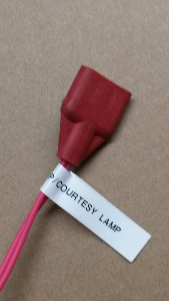
(pic19)

1) 2 solid yellow wires to 3 port black mold
A) Lamp ground
B) for map, courtesy lamp, open door indicator lamp, rear door light switch
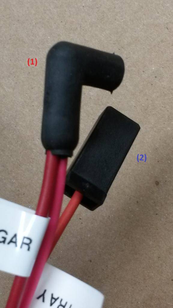
(pic20)
1) yellow wire with black stripe, solid yellow wire
A) right front door automatic switch
B) passenger door switch
(pic21)
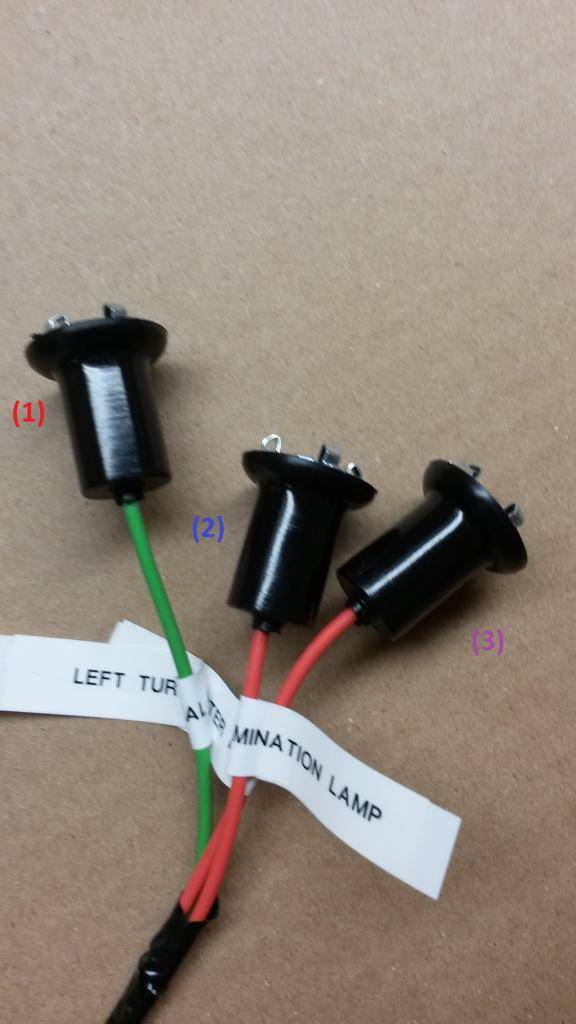
1) solid light green wire
A) left turn signal indicator lamp
B) back of rallye dash
2) solid orange wire
A) cluster illumination lamp
B) back of rallye dash
3) solid orange wire
A) cluster illumination lamp
B) back of rallye dash
(pic22)
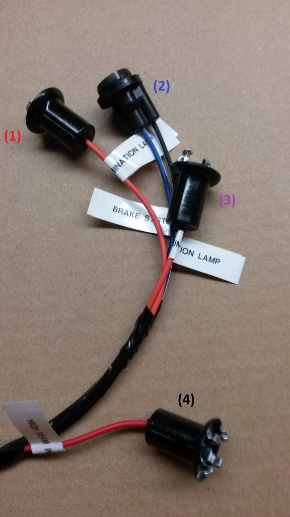
1) solid orange wire
A) cluster illumination lamp
B) back of rallye dash
2) back wire with white stripe, dark blue wire with white stripe
A) brake system warning lamp
B) back of rallye dash
3) solid orange wire
A) cluster illumination lamp
B) back of rallye dash
4) solid red wire
A) high beam indicator lamp
B) back of rallye dashBuild Thread!!!https://www.pro-touring.com/showthread.php?88692-1971-Speedipus-Rex&p=925864&posted=1#post925864
02-18-2015 #52
Registered User
- Join Date
- Mar 2012
- Location
- Lethbridge, AB
- Posts
- 177
(pic23)
1) 2 solid yellow wires, 2 solid light green wires, one solid tan wire, one solid pink wire, one black wire with white stripe, one black wire with yellow stripe, one solid black wire
A) headlamp switch
B) headlamp switch back of rallye dash
(pic24)

1) is a 71 setup... the one piece plug to wiper switch began on 72, when wiper switches were smaller. Same wires though on diff prongs disposition
A) windshield wiper switch
B) wiper switch back of rallye dash
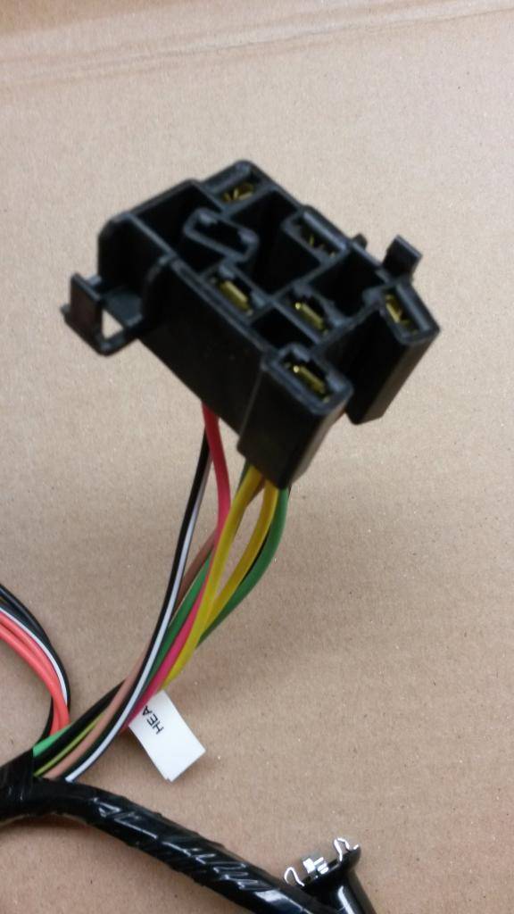
(pic25)

1) **the M&H harness just came with the black wire with white stripe, I had to add this to the red connector myself**one solid dark green wire, one solid light green wire, one solid brown wire, black wire with white stripe
A) heater blower switch
B) heater blower under dash passenger footwell, heater and A/C harnesses are separated from the underdash harness and instead are just linked ( according with your car equipment ) with the Underdash harness they are used to switch the input on the bulkhead for blower source green wire ( and blue wire clutch if AC ). If you had A/C must use the empty cavity on the A/C harness ( pic 49#2 ) to insert it there the black traced wire is left alone on the Underdash harness, just like I did with Heater harness.
(pic26)
(pic26a)
1) 2 solid orange wires, one solid black wire, one black wire with white stripe
A) light for Heater-A/C control face
B) plugs into a small pigtail harness for it using dual bulb on 71/72 correctly shown on 26 A (use from your existing harness)
(pic27)

1) solid orange wire to 3 port orange mold
A) accessory title lamp
B) lamp source for accessories switch under the dash... Air Ram, Rear Deffog, whatever switch down the dash driver side
2) solid orange wire
A) ***from your old harness***
B) orange circuit is for cluster dimmed sources. Center console is the one I meant which dims out the same than cluster, and also radio faceplate ( hence the orange wire arriving to Radio )
3) solid orange wire
A) ***from your old harness***
B) orange circuit is for cluster dimmed sources. Center console is the one I meant which dims out the same than cluster, and also radio faceplate ( hence the orange wire arriving to Radio )
(pic 28)
1) black wire with white stripe
A) parking brake lamp switch
B) to a switch on the emergency brake that triggers a light in the dash when the emergency brake is engaged or if the brake pressure fails. The switch is just a ground to activate the light.
2) 2 solid light green wires
A) time delay for headlights
B) delay relay gets an extra harness for that plug, separate option on B bodies, more common on C bodies
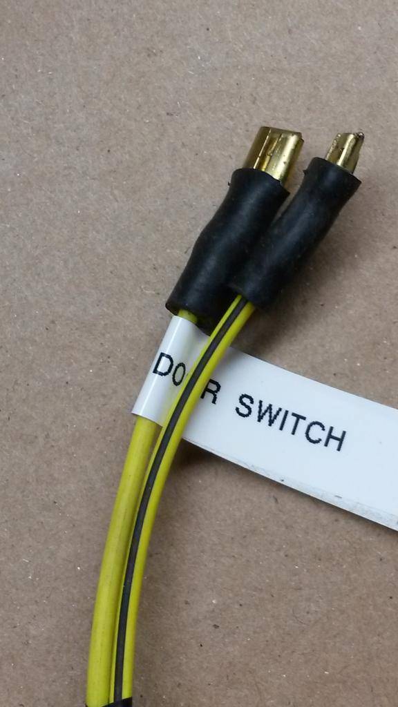
(pic 29)
1) one solid yellow wire, one yellow wire with black stripe, one solid black wire
A) left front door automatic switch
b) driver's side door
(pic 30)

1) solid black wire
A) harness ground
B) actually the underdash frame gets a J nut attached around the emergency brake area. Thats a ground source for the harness.
(pic 31)

1) solid dark blue wire, solid black wire, solid dark green wire, solid brown wire, 2 solid pink wires, white wire with black stripe
A) rear body harness to rear lights
B) yes some colors won't match... its on that way from factory. white with black trace becomes in violet for example... some other changes too.
2) solid pink wire, 2 solid yellow wires
A) to dome lamp
B) dome lamp harness , driver's side kickpanel
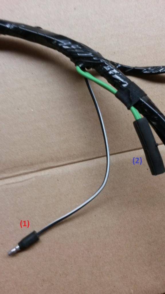
(pic32)

(pic32a)
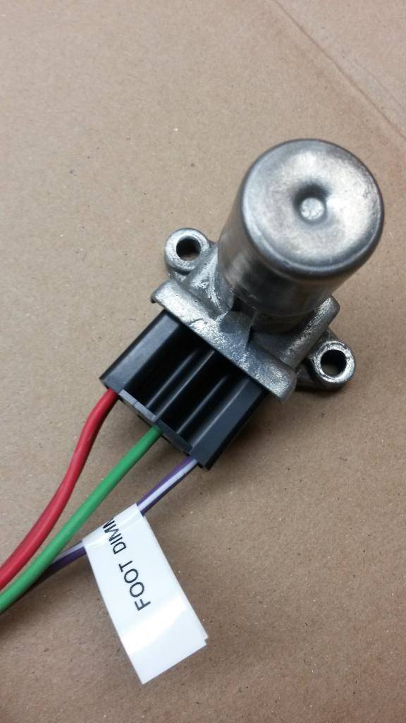
1) violet wire with white stripe, solid light green wire, 2 solid red wires
A) foot dimmer switch
B) driver's side floor pan
Rear lamp harness (M&H Electric / YO)
(pic33)
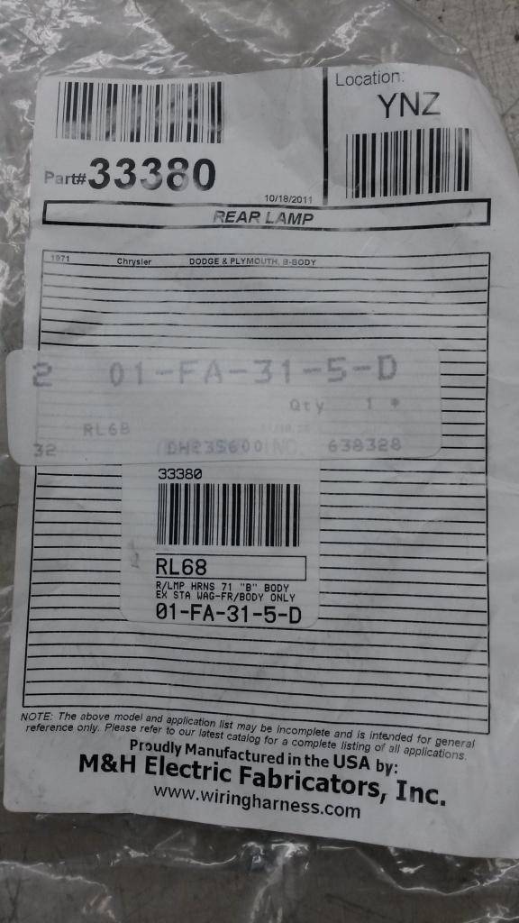
(pic34)

1) solid dark blue wire, solid black wire, solid dark green wire, solid brown wire, solid grey wire, solid violet wire
A) rear lamp harness
B) to body wiring harness on main harness
(pic35)
1) solid violet wire, solid dark green wire, solid brown wire, solid black wires
A) rear taillights
B) rear taillight harness in trunk drivers side
2) solid black wire
A) taillight ground
B) ground to body
(pic35b)
1) solid grey wire, solid black wire
A) rear driver's side marker lamp
B) rear driver's side marker lamp housing
2) solid grey wire
A) rear driver's side marker lamp ground
B) ground to body
(pic35c)
1) solid dark blue wire
A) sending unit
B) sending unit mounted in gas tank
(pic35d)

1) solid grey wire
A) trunk lamp (optional)
B) It plugs into the dark blue wire male end for the rear trunk light if you have the lighting package
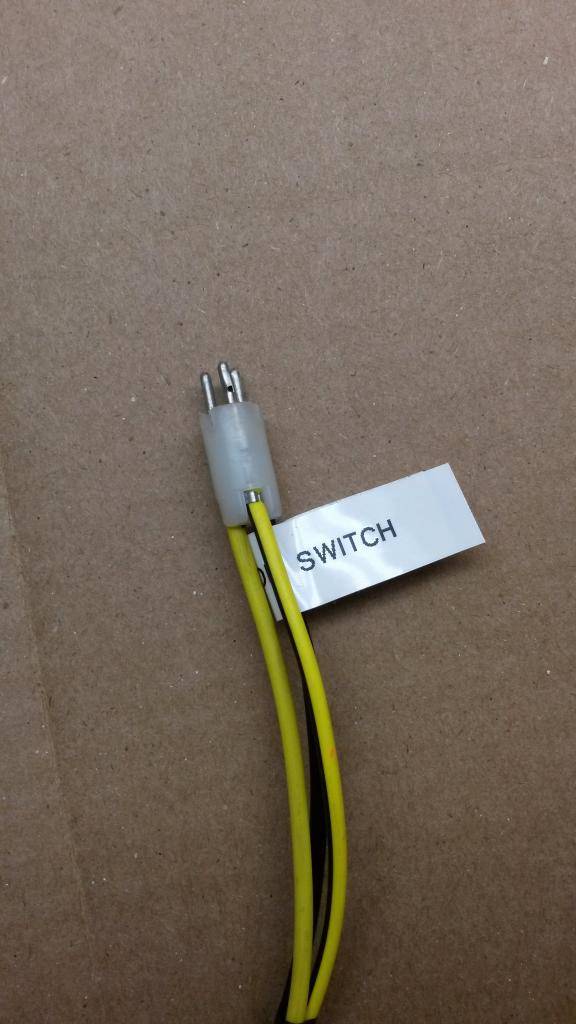
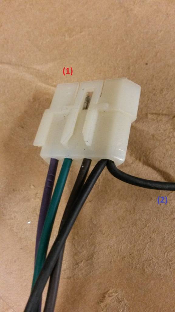
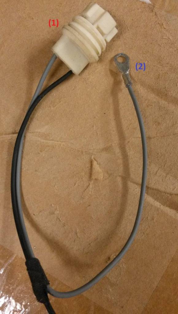
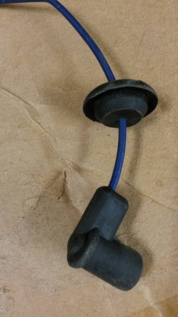
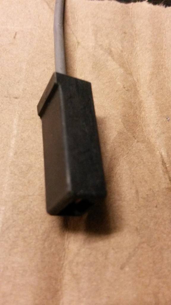
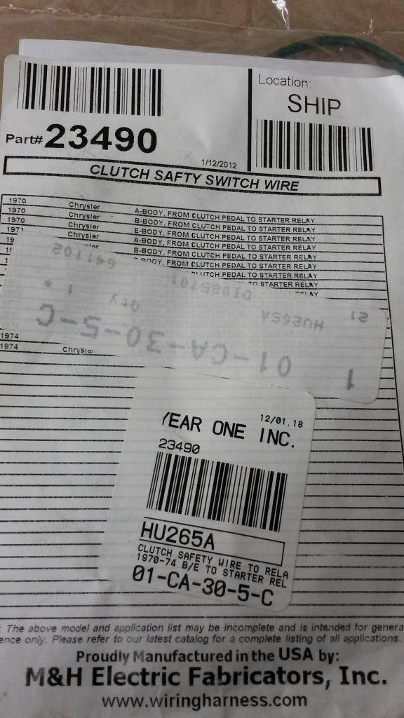
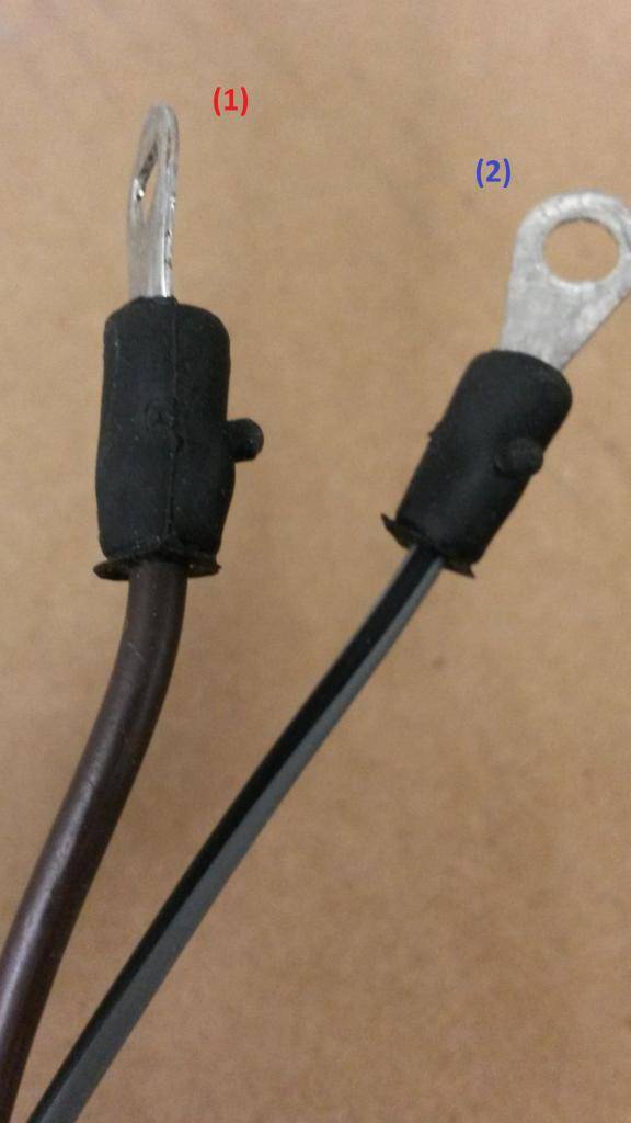
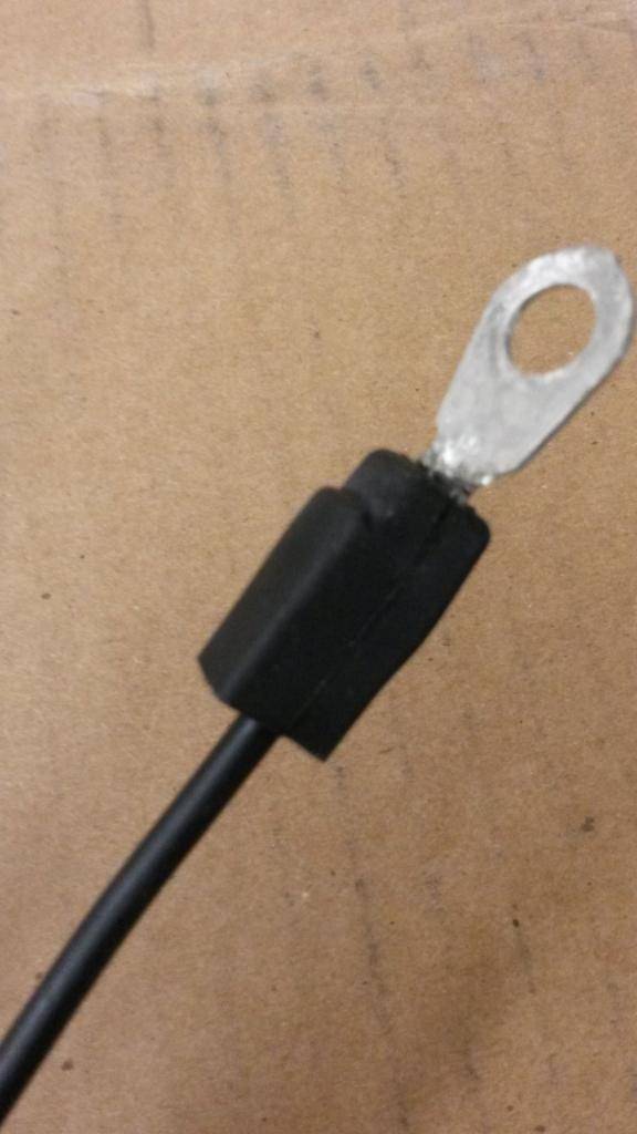
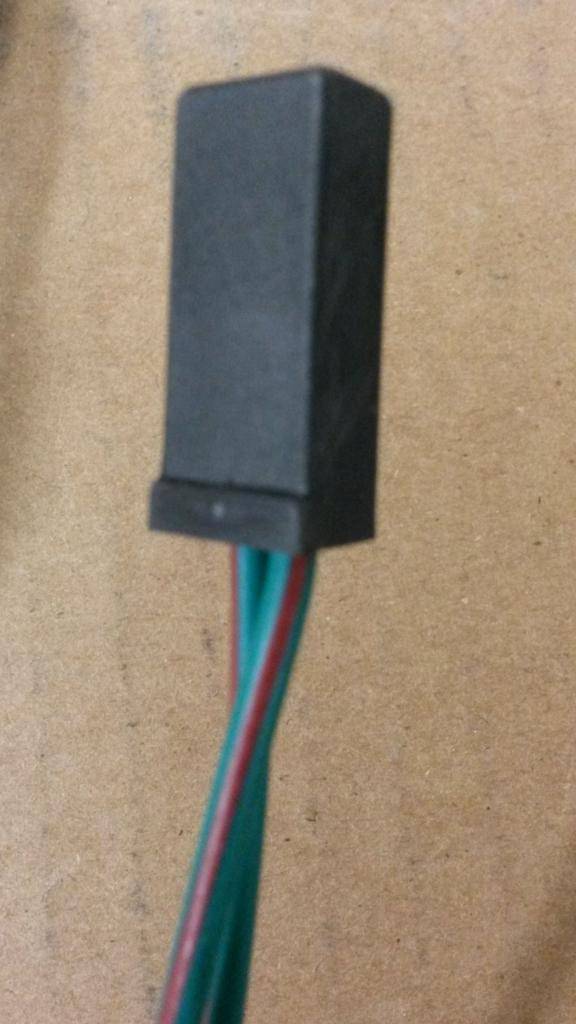
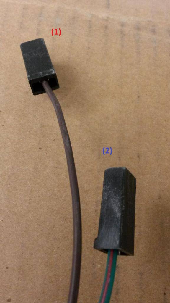
Clutch Safety Switch Wire (M&H Electric / YO)
(pic36)
(pic37)
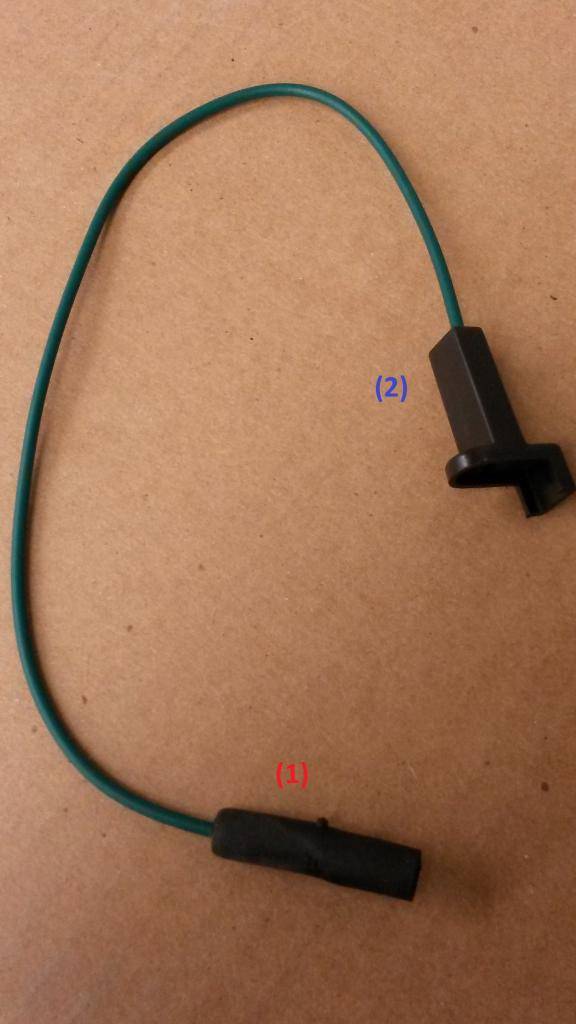
1) solid dark green wire
A) clutch safety switch wire
B) to a single wire with a grommet through firewall when car is manual transmission
2) solid dark green wire
A) clutch safety wire
B) to starter relay "G" prong (when auto, this prong on relay gets the source from NSS tranny harness )
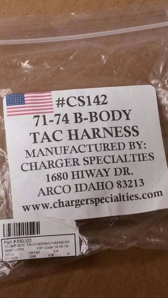
Tach Harness (Charger Specialties / YO)
(pic38)
(pic39)
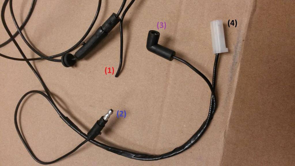
1) solid black wire
A) tachometer harness
B) negative post on ignition coil
2) solid black wire
A) tachometer harness
B) to yellow accessory yellow mold
3) solid black wire
A) tachometer harness
B) back of tachometer
4) solid black wire
A) tachometer harness
B) back of tachometer
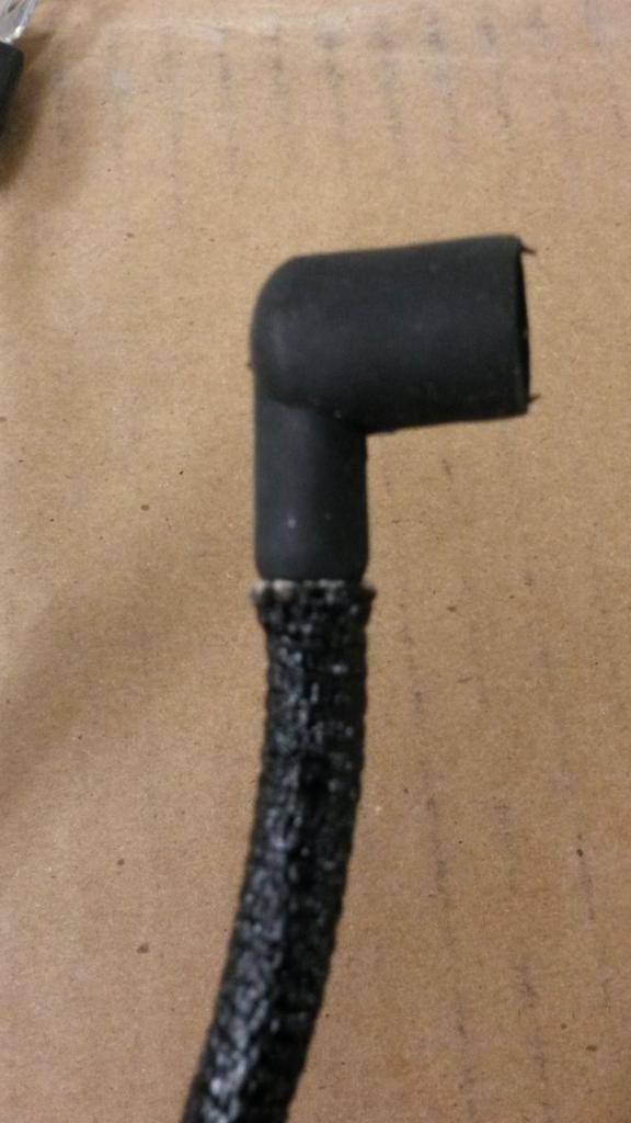
Electronic Ignition Conversion Harness (Mopar / YO)
(pic40)

(pic41)
1) green with red stripe
A) un-used in 4 pin ecu,
B) on 5 pin ecu, goes to "auxiliary" post ballast resistor
2) light blue with yellow stripe
A) ballast resistor "run" wire
B) "run side of ballast resistor
3) black with yellow stripe
A) ignition coil
b) to ignition coil negativeBuild Thread!!!https://www.pro-touring.com/showthread.php?88692-1971-Speedipus-Rex&p=925864&posted=1#post925864
02-18-2015 #53
Registered User
- Join Date
- Mar 2012
- Location
- Lethbridge, AB
- Posts
- 177
(pic42)
1) dark blue with white stripe, solid dark blue wire
A) distributor connector
B) on the distributor
(pic43)

1) blue with white stripe, solid blue wire, black with yellow stripe, green with red stripe, light blue with yellow stripe
A) control unit ecu harness
B) on the control unit on the firewall
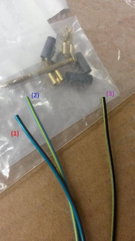
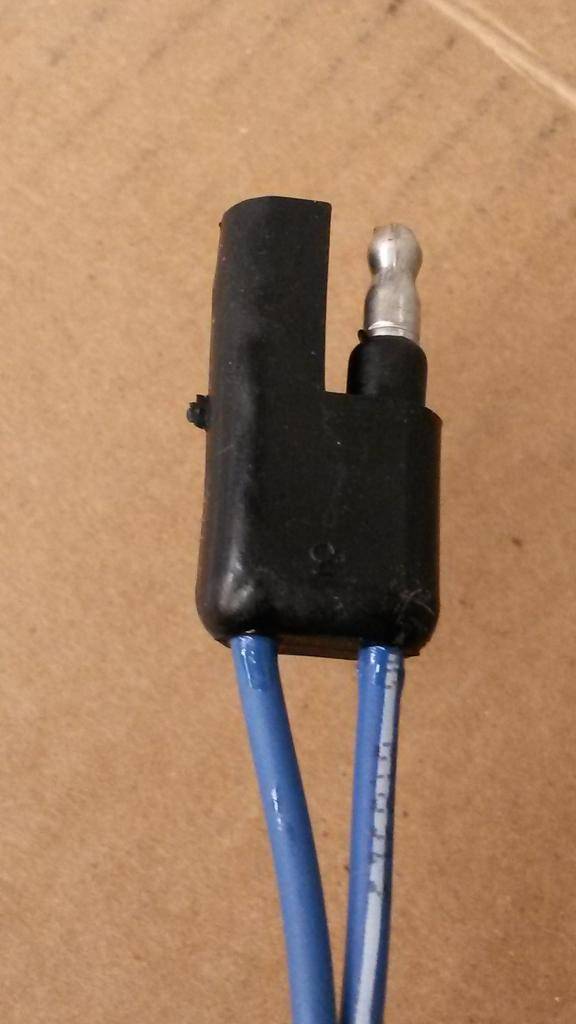
Windshield Wiper Harness (M&H Electric / YO)
(pic44)
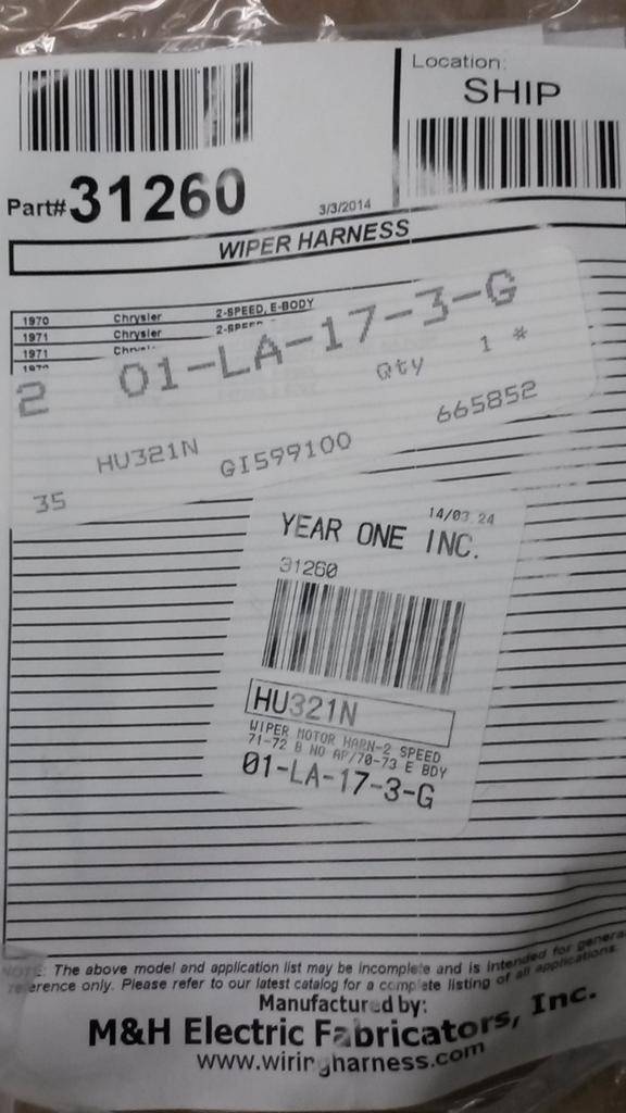
(pic45)
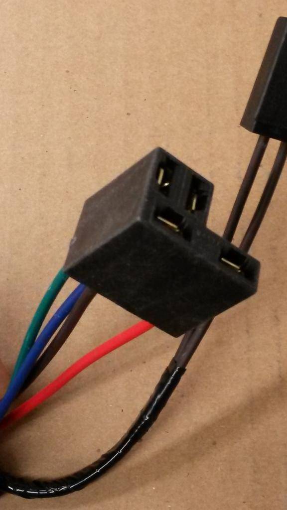
(pic46)

(pic47)
1) solid red wire, solid brown wire, solid dark blue wire, solid dark green wire
A) wiper harness
B) windshield wiper motor
2) solid brown wire
A) ballast resistor
B) ballast resistor on wiper motor
3) solid brown wire
A) ballast resistor
B) ballast resistor on wiper motor
4) solid dark blue wire, solid red wire, solid dark green wire, solid brown wire
A) wiper harness
B) main fuse block
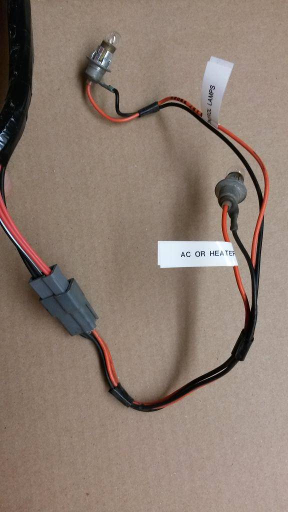
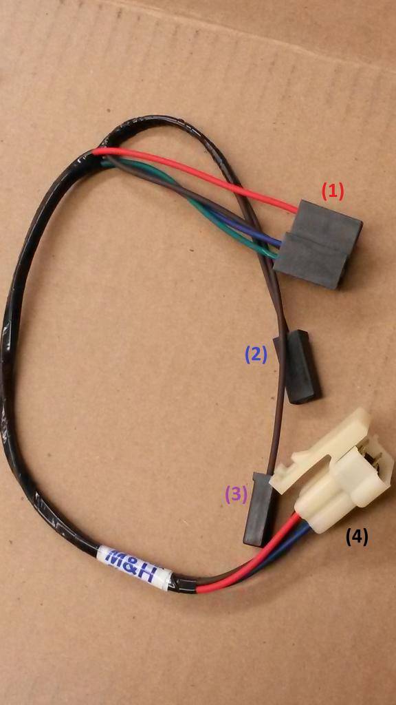
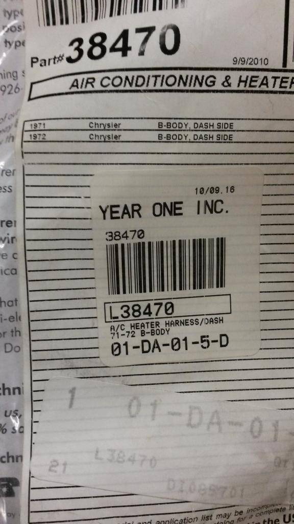
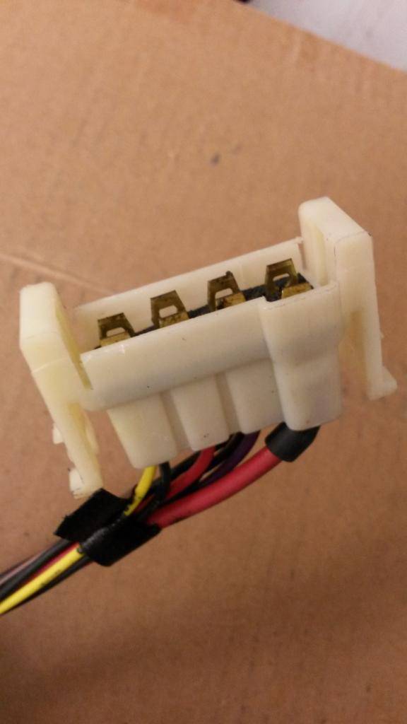
AC / Heater Harness (M&H Electric / YO)
(pic48)
(pic49)
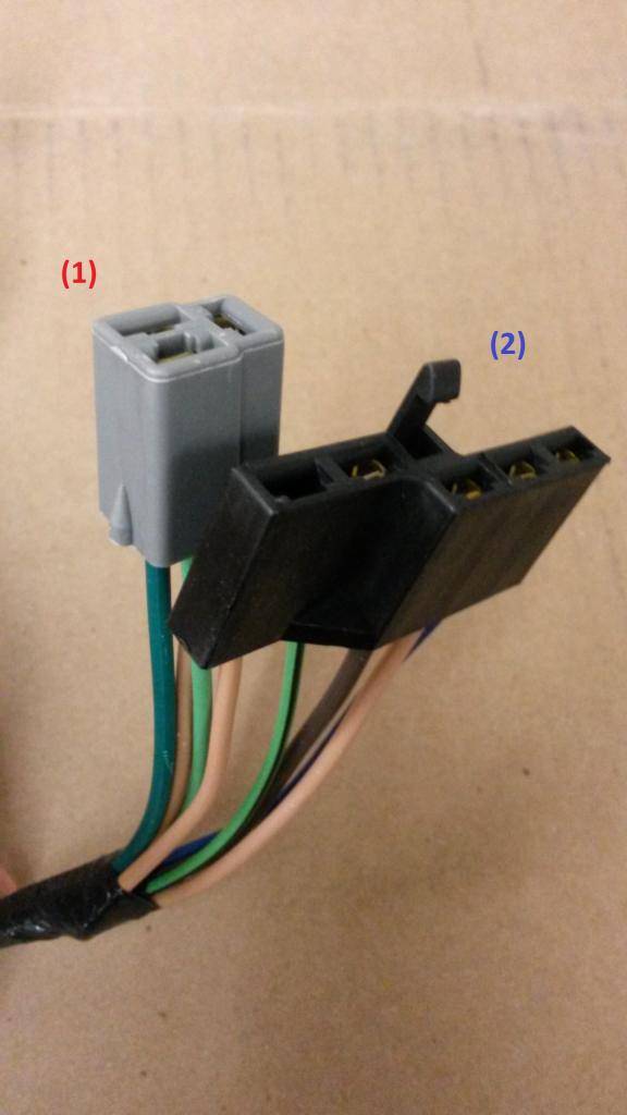
1) 2 solid tan wires, one solid light green wire, one solid dark green wire
A) blower switch
B) on back of rallye dash
2) light green wire with black stripe, solid brown wire, tan wire, one dark blue wire
A) AC and heater control switch
B) on back of rallye dash
(pic50)
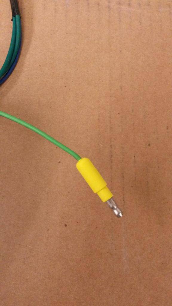
1) solid light green wire
A) clutch feed
B) yellow mold accessory feed
(pic51)
1) solid dark blue wire
A) clutch
B) just on 71 they used cavities left empty on neutral safety switch harness. 72/73 where shared between engine harness an NSS harness, using the green ( blower ) on NSS harness plug and Blue ( clucth ) on engine harness. 74s got a separate grommet for that on firewall due the lack of cavities left
2) 2 solid dark green wires
A) blower
B) same answer as 1B
(pic52)

1) solid tan wire
A) heater motor resistor
B) on the motor in the passenger footwell
2) solid light green wire, solid dark green wire, solid brown wire
A) heater motor resistor
B) on the motor in the passenger footwell
Engine Harness For A 383-440 W/O Six Pack (M&H Electric / YO)
(pic54)
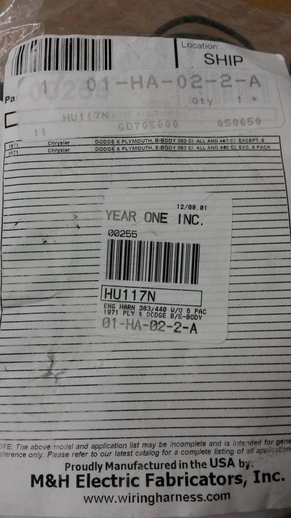
(pic55)
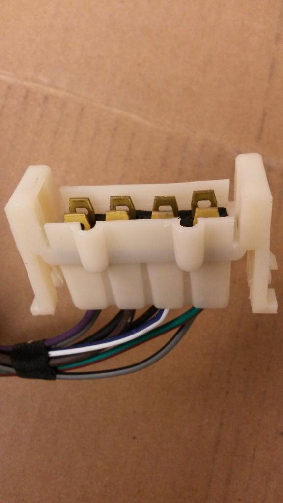
1) solid grey wire, solid black wire, solid brown wire, grey wire with black stripe, dark green wire with red stripe, dark blue wire with white stripe, solid brown wire, solid violet wire
A) engine harness
B) plugs into main bulkhead
(pic56)

1) 2 solid brown wires
A) ignition ballast/resistor
B) above windshield wiper motor
(pic57)

1) dark blue wire with white stripe
A) ignition ballast/resistor
B) above windshield wiper motor
(pic58)
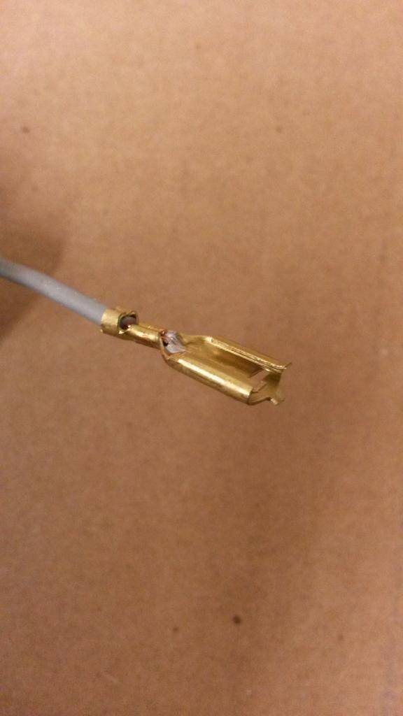
1) solid grey wire
A) oil gauge wire
B) oil pressure switch on back of engine
(pic59)

1) solid dark green wire, dark blue with white stripe
A) alternator regulator
B) on the voltage regulator on firewall
(pic60)

1) solid dark blue wire
A) carburetor solenoid
B) on carburetor
(pic61)
1) solid brown wire
A) ignition coil
B) positive post on the ignition coil
2) grey wire with black stripe
A) not used on GTX/Roadrunner/Satellite
B) Can be used for the TACHOMETER WIRE... negative lead of coil...the tach harness can use this cavity on back oh bulkhead ( number 20 ) instead use the grommet on harness to go through firewall
(pic62)
1) solid dark blue wire, dark blue wire with white stripe
A) from the ignition resistor/ballast
B) back of alternator
2) solid dark green wire
A) alternator field
B) back of alternator
(pic63)
1) solid black wire
A) Ammeter gauge wire
B) back of alternator
(pic64)
1) solid violet wire
A) temperature gauge sending unit
B) temperature switch on engine
(pic65)
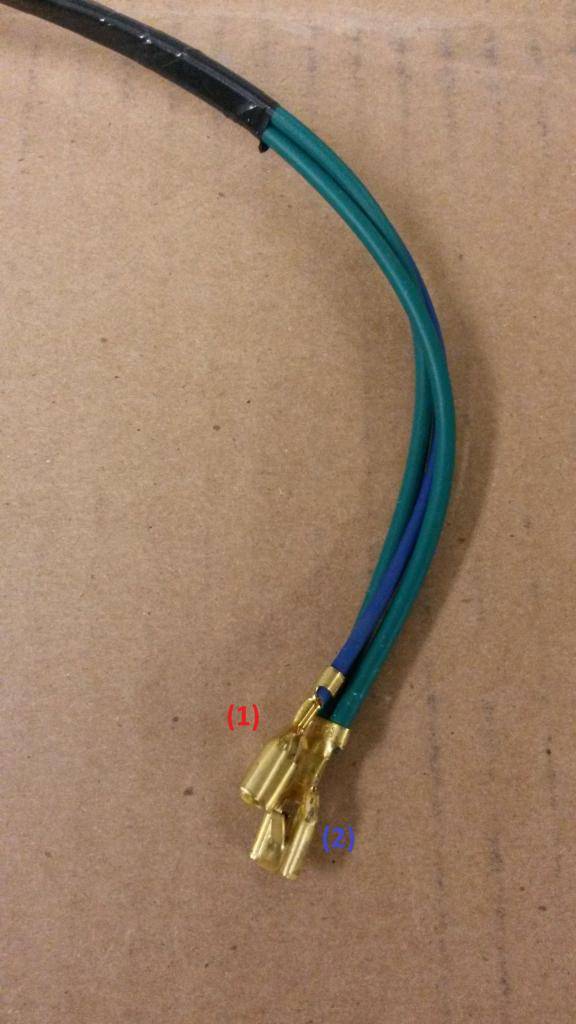
1) 2 dark green wires with red stripe
A) horn
B) for those equipped with dual horns
(pic66)
1) solid brown wire
A) windshield washer motor?
B) windshield washer fluid bottle in the front passenger engine bay
2) dark green wire with red stripe
A) horn
B) horn front passenger engine bayBuild Thread!!!https://www.pro-touring.com/showthread.php?88692-1971-Speedipus-Rex&p=925864&posted=1#post925864
02-18-2015 #54
Registered User
- Join Date
- Mar 2012
- Location
- Lethbridge, AB
- Posts
- 177
Front Lamp Harness (M&H Electric / YO)
(pic67)

(pic68)
1) solid red wire, violet wire with white stripe, solid red wire, black wire with green stripe, solid black wire, black wire with brown stripe, black wire with yellow stripe, solid yellow wire
A) front lamp harness
B) bulkhead connector on firewall
(pic69)
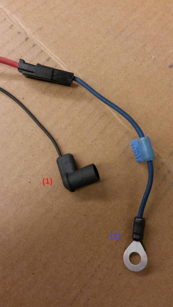
1) solid black wire
A) low brake switch
B) located on your brake distribution block
2) solid red wire to solid blue wire
A) ammeter feed
B) to the "B" on the starter relay
(pic70)
1) solid yellow wire
A) starter relay
B) to the "I" on starter relay
(pic71)

1) 2 solid black wires
A) harness ground
B) on radiator core support
(pic72)
1) 2 solid red wires, 2 solid black wires
A) left high beam lamp
B) inside lamp front grill, driver's side
(pic73)
1) 2 solid red wires, 2 violet wires with white stripe, 2 solid black wires
A) left low beam lamp
B) outside lamp front grill, driver's side
(pic 74)

1) solid black wire, black wire with yellow stripe
A) left marker lamp
B) inside driver's front fender
2) solid black wire, black wire with yellow stripe, black wire with green stripe
A) left parking light
B) front valance driver's side
(pic75)
1) 2 solid red wires, 2 solid black wires
A) right high beam lamp
B) inside lamp, front grill passenger side
(pic76)
1) solid black wire, solid red wire, violet wire with white stripe
A) right low beam lamp
B) outside lamp, front grill passenger side
(pic77)
1) solid black wire, black wire with yellow stripe,
A) right marker lamp
B) inside front passenger fender
2) solid black wire, black wire with yellow stripe, black wire with a brown stripe
A) right parking light
B) front valance passenger side
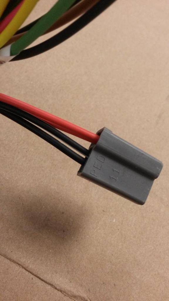
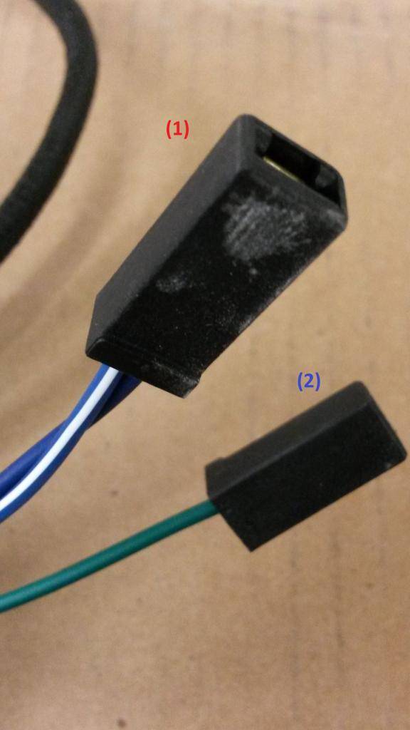
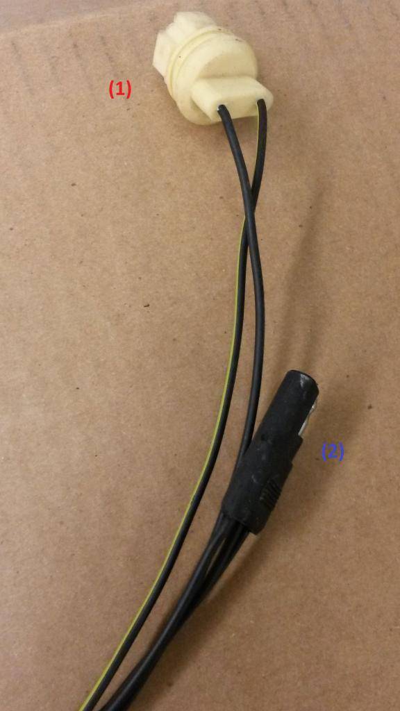
Backup Light Harness (Brewers Performance)
(pic78)

1) solid black wires with black female 2 prong female plug end (3 prong for AutoTransmission)
A) for the backup lights
B) switch on drivers side of transmission
2) solid black wire, black wires with white stripe
A) for the backup lights
B) plugs into main bulkhead
3) black wire with white stripe with grey female connector
A) reverse light on dash
B) reverse light dash wire
WIRING DIAGRAMS FOR REFERENCE:
http://www.mymopar.com/downloads/197...%20RunnerA.JPG
http://www.mymopar.com/downloads/197...oadRunnerB.JPGBuild Thread!!!https://www.pro-touring.com/showthread.php?88692-1971-Speedipus-Rex&p=925864&posted=1#post925864
04-09-2015 #55
Registered User
- Join Date
- Mar 2012
- Location
- Lethbridge, AB
- Posts
- 177
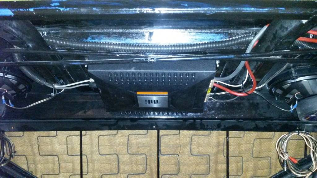
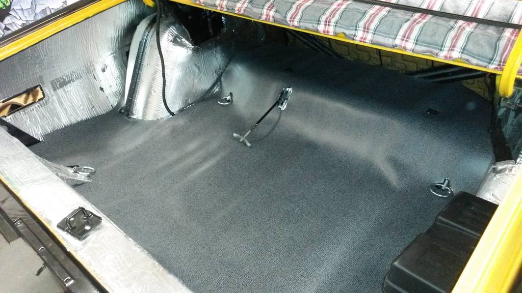
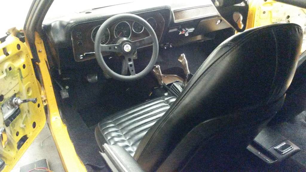
so its been awhile since my last post, been working mostly on the new wiring for the car, its kinda hard to see what lies hidden, but all the wiring in the interior of the car is now done, just currently working on the engine bay harnesses. Finished my wiring guide, I have also got around to finishing up some loose ends:
wired my amp under the package tray out of sight
radio now in the glovebox

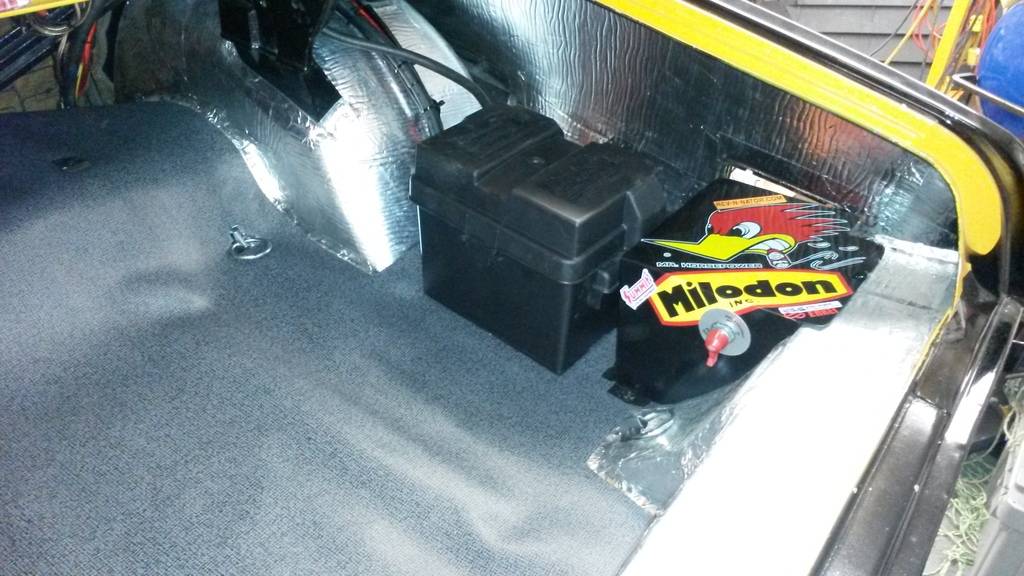
battery in the back complete with all my relays hidden and battery disconnect in the trunk (for now)
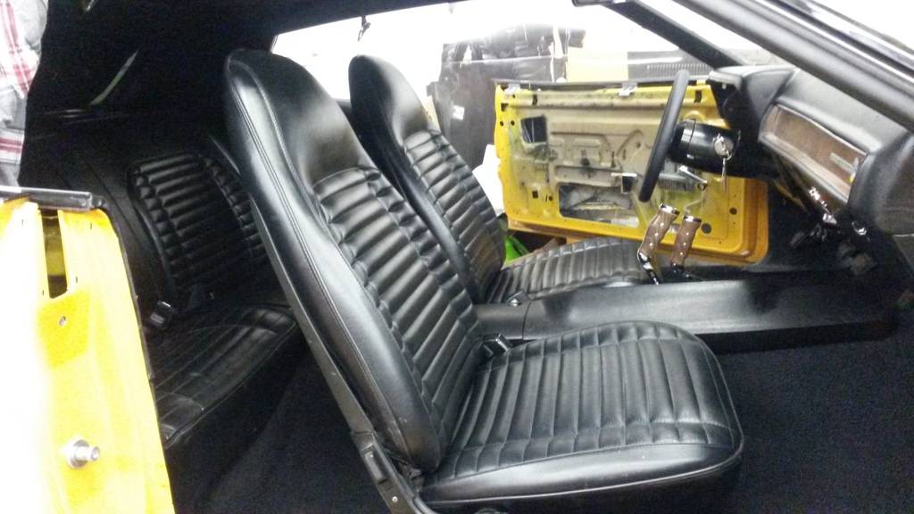
floor mat all done
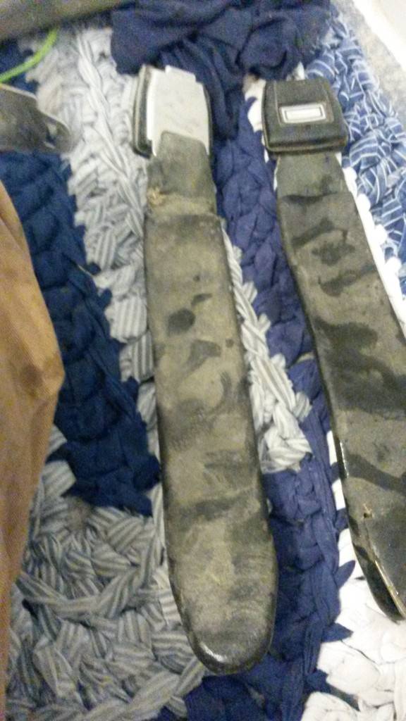
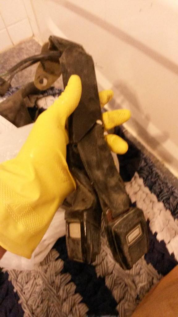
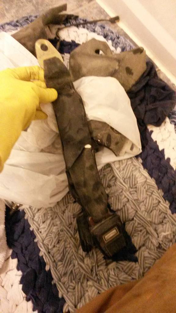
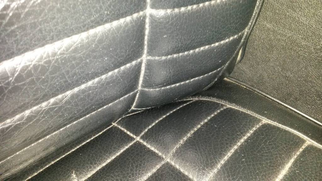
cleaned up all of my seatbelts ready for install:


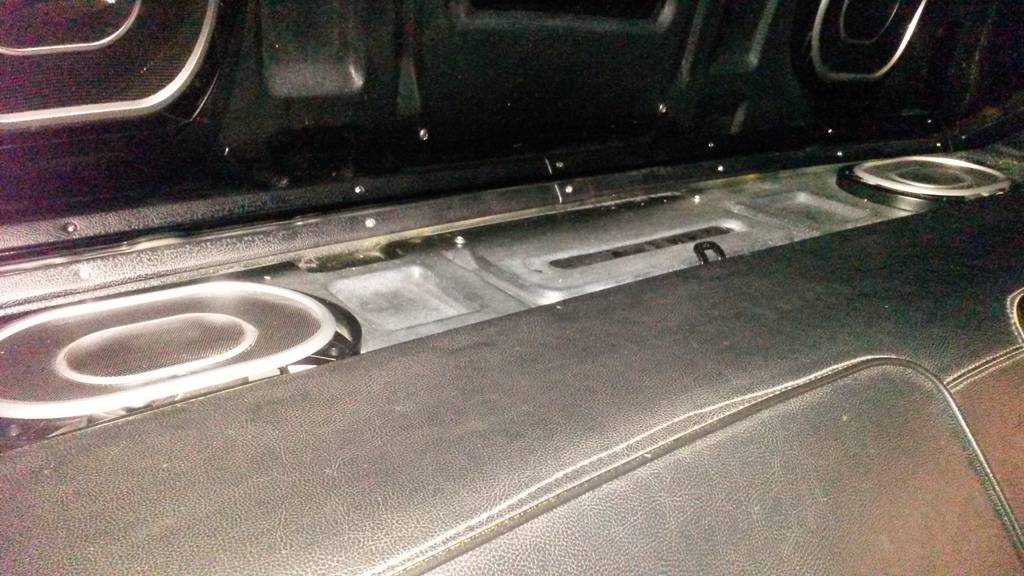
so I have two boys now, one in a baby seat, other in a child seat. We plan on maybe having one more down the road. You can buy child anchors for child seats, which I installed here in the package tray in front of the speakers and one in the middle:
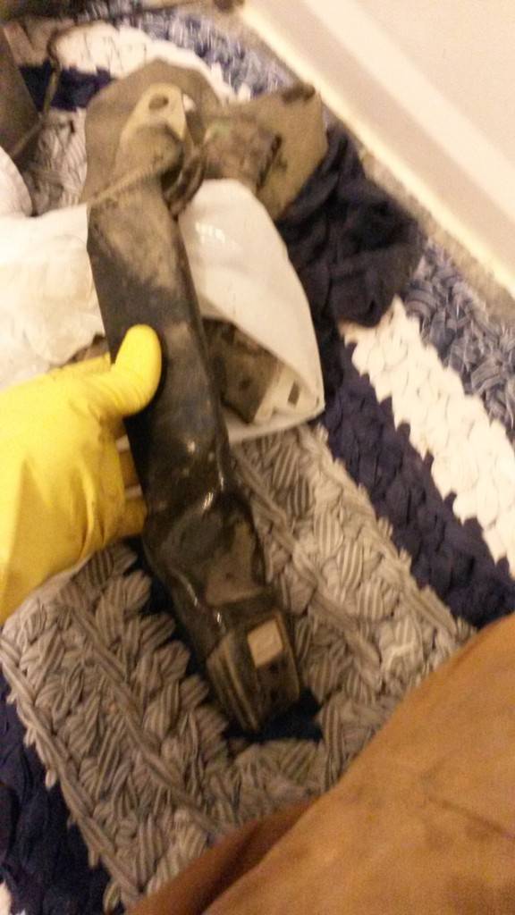
The problem is this. No one, and I mean NO ONE sells a set of the lower metal latch systems used on baby seats that are in all of the modern cars today, I've tried aftermarket, dealerships ect. So realizing this I came to make up my own I made from used racing belt anchors, heck if it can hold back a 300lbs adult, a 20 lbs baby should be easy. I had to dremel the holes out about a 1/16" so the latches from the seat could hook onto them. The brackets are made from 1/4" flat bar and grade 8 hardware, (overkill I know) but they are holding my baby boys!
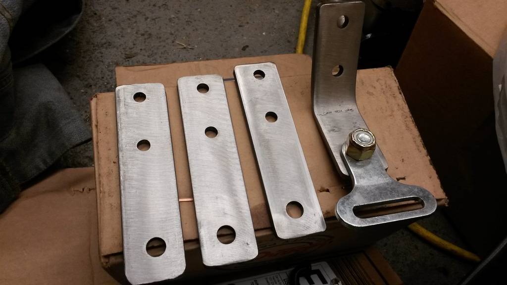
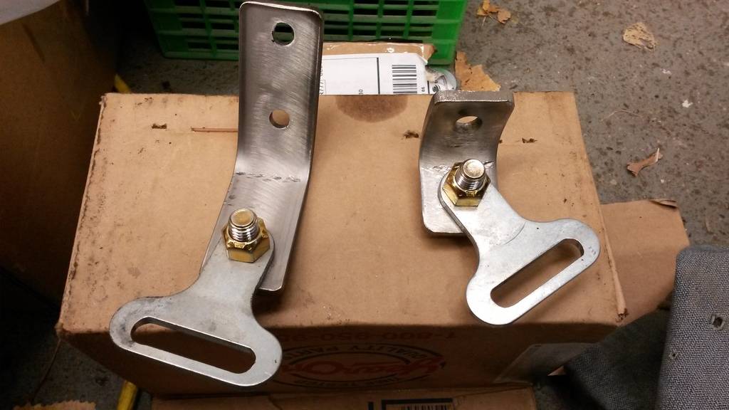
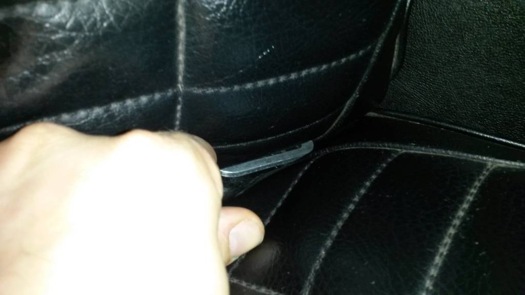
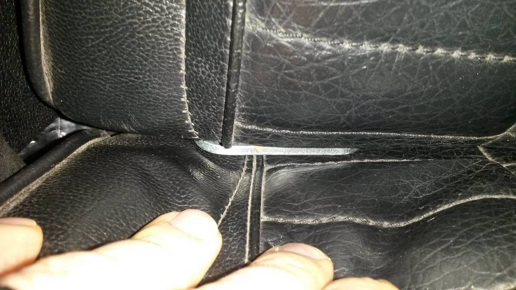
I had to cut two of them down to mount on the wheel well and angle the hooks with the top half of the rear seat in so they are about 1/4 -1/2" sunk in out of sight until you need them.

once the seats were installed, you can't see them until you push them back for use! So now I can have 3 babies in the rear seat, or 3 children, or a combination of the two!


with that out of the way I can finish the interior!
 Build Thread!!!https://www.pro-touring.com/showthread.php?88692-1971-Speedipus-Rex&p=925864&posted=1#post925864
04-09-2015 #56
Registered User
- Join Date
- Mar 2012
- Location
- Lethbridge, AB
- Posts
- 177
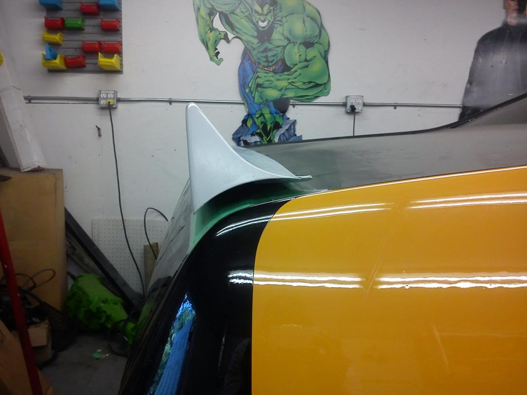
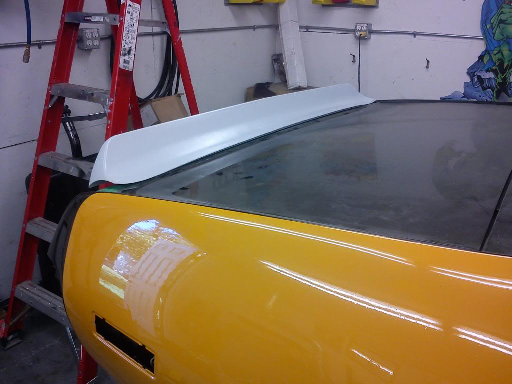
I had also got to finishing mounting my rear 69 Camaro spoiler, Here it is from start to finish:
First mask off the area your with green painters tape, saves the paint for underneath and allows you to mark on it. Position where you want the spoiler to sit, and with a measuring tape mark where the tips of your spoiler will sit, I measured from the trunk edge, then from the sides, the tips sit about an 1/4" from the edge:
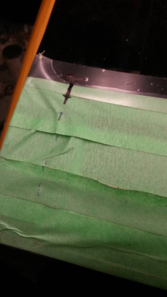

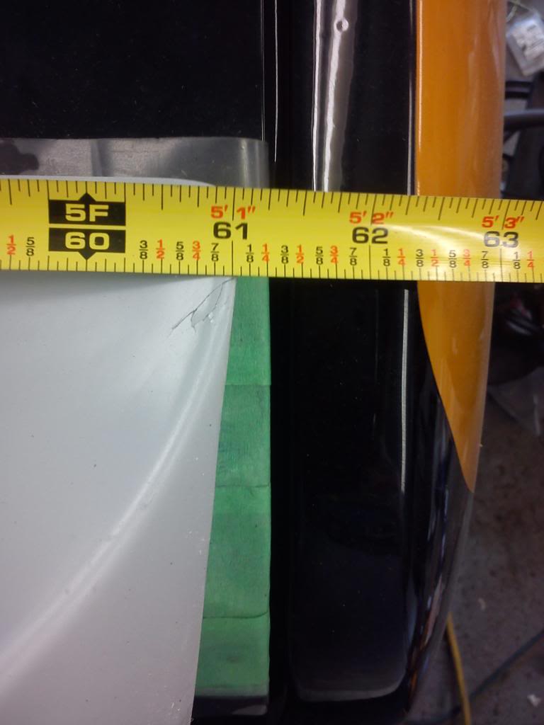
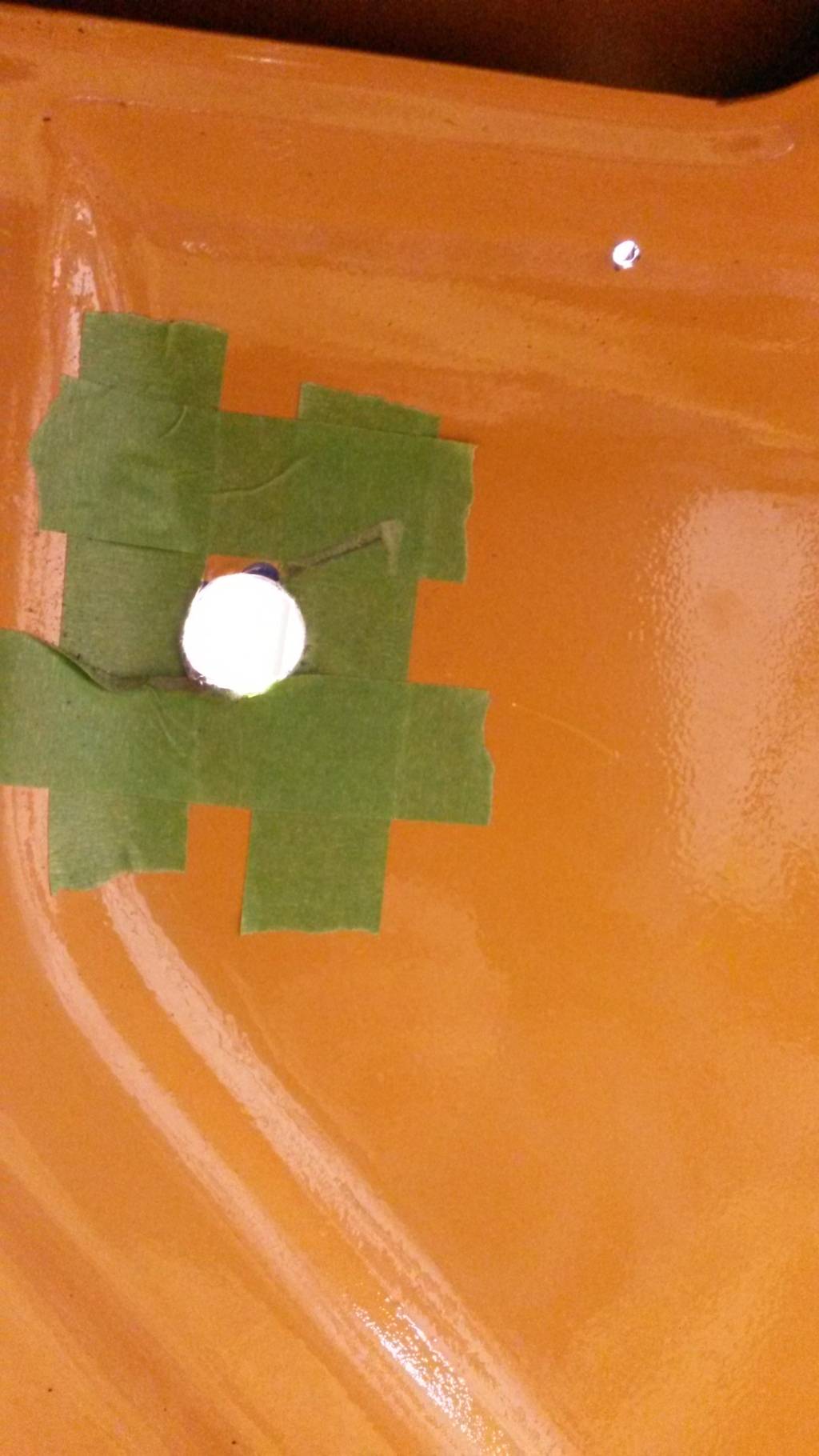
When you figured out where she' gonna sit, you wanna mark out the stud locations for the spoiler and drill small holes and see if that's where they need to be before making them bigger (I bought two spoilers 69 and a 68, the 68 is 2" shorter so I sold it) they have the same stud location and both of them came with a template, but I noticed that the studs weren't mounted in the same place, even though they were both made by the same company, they could get up to almost a 1/2" out. ouch. After you have the size of the holes you want I drilled in the center from the outside going in so I know where to drill them underneath:
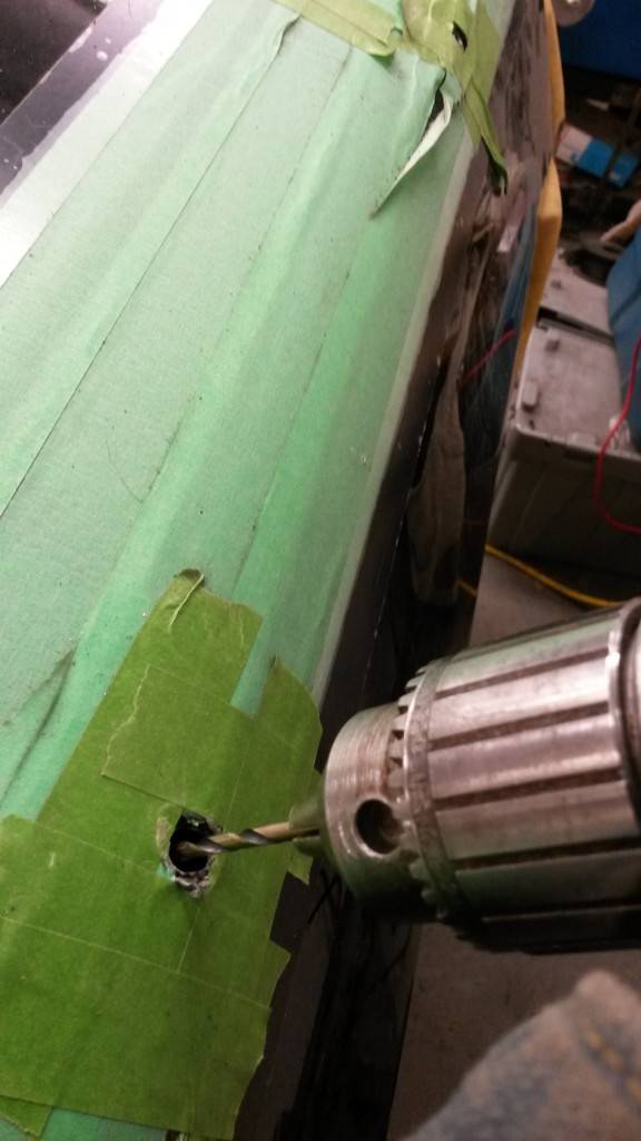
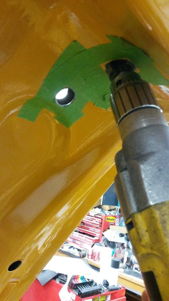
Underneath I would mask the area off around the hole and drill out to the size you want:
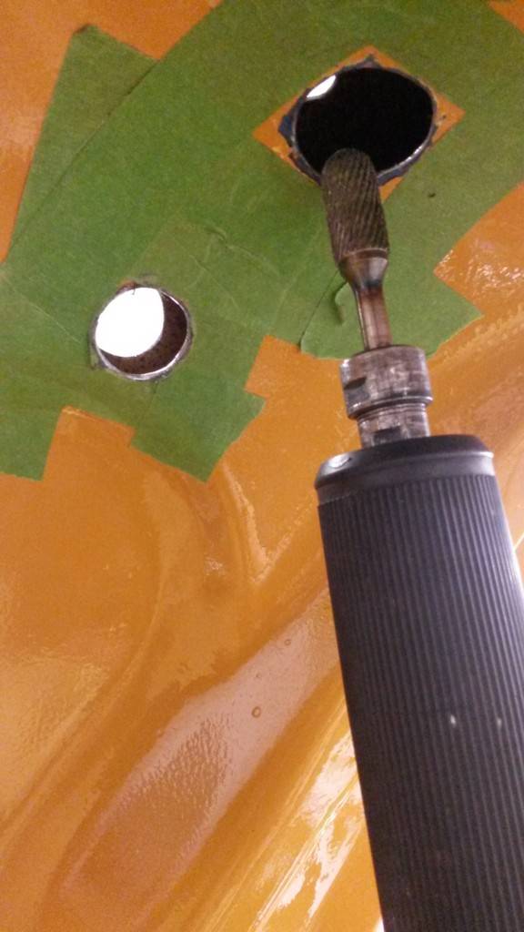
I went a little bigger than I thought, I was thinking maybe down the road if I had to buy another rear spoiler for whatever reason(carbon fiber perhaps?), I would have plenty of room for the studs if they end up being off like the ones I had. you can use a hole saw, I used a stepper bit for the weird corner ones and cleaned up with a dremel, and don't forget to file off your sharp edges!

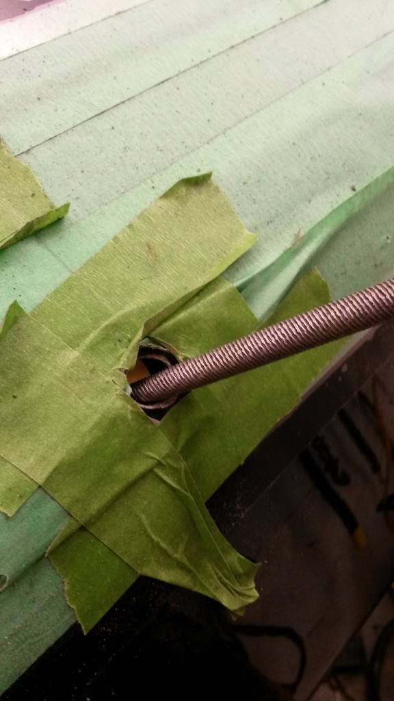

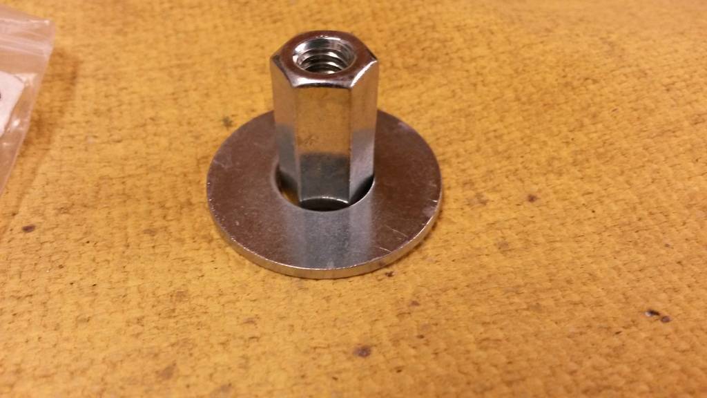
Now that we have all the holes done were gonna have to mount this somehow. The 4 studs on the back of the trunk can be held down with your standard washers and locknuts, but the front studs being more accessible I have a better Idea, I bought these flat washers and these allthread connectors that fit inside the washers:

With the spoiler in place, thread the connector all the way till it bottoms out, the back it off a couple turns and weld the washer in place:
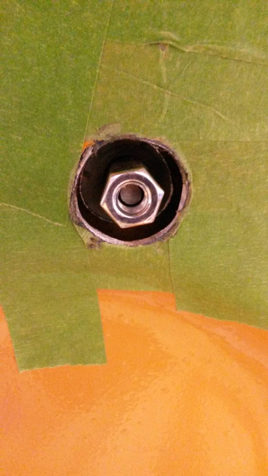
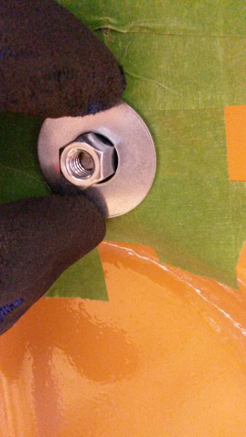
I put a spot weld just to hold it in place:

Then you can weld them up!
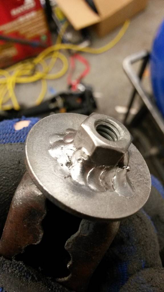
Now you have a custom nut that you can tighten all the way down and not worry about it bottoming out on the stud!
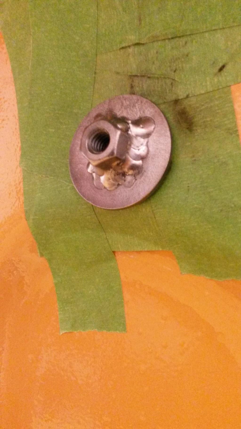
I painted them, but you could powder coat them:
Before your put your spoiler on be sure to use some sort of gasket material, I'll be using gasket maker, doesn't harm the paint underneath and not bad to clean up.
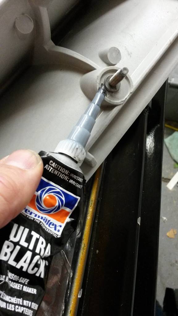
And it finishes off like this! I used 3/4" body plugs to hide the inner access holes for the rear studs, I did the outter access rear holes the same size as the trunk body plugs at 1 1/4" (Please excuse the flaking paint, something I have to have a talking to about with my painter in the very near future)
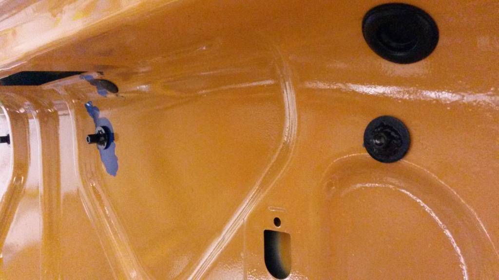
Hopefully you have something similar to this when your finished! (without the painters tape and the spoiler painted lol)
 Build Thread!!!https://www.pro-touring.com/showthread.php?88692-1971-Speedipus-Rex&p=925864&posted=1#post925864
04-10-2015 #57
Starting The Transformation
- Join Date
- Jan 2015
- Location
- Charlotte, NC
- Posts
- 309

Love the refurb of the gauges and cluster!
04-12-2015 #58
Registered User
- Join Date
- Mar 2012
- Location
- Lethbridge, AB
- Posts
- 177
Thanks man! since then i actually picked up and installed the vary rare radio delete bezel Originally Posted by Justin@EntropyRad
Build Thread!!!https://www.pro-touring.com/showthread.php?88692-1971-Speedipus-Rex&p=925864&posted=1#post925864
05-12-2016 #59
Registered User
- Join Date
- Mar 2012
- Location
- Lethbridge, AB
- Posts
- 177
wow I'm in serious need of an update!!! Here's what I got in photos on here so far, I gotta upload more her in the next few days....
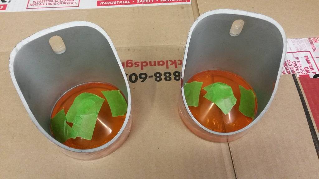
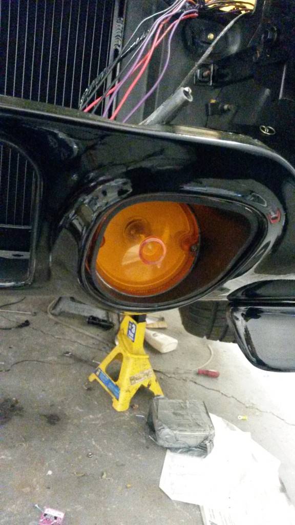
so I plastidipped the front marker lights so I don't ruin the originals (I love this stuff!)

Re-did the rear taillamp wiring harnesses:

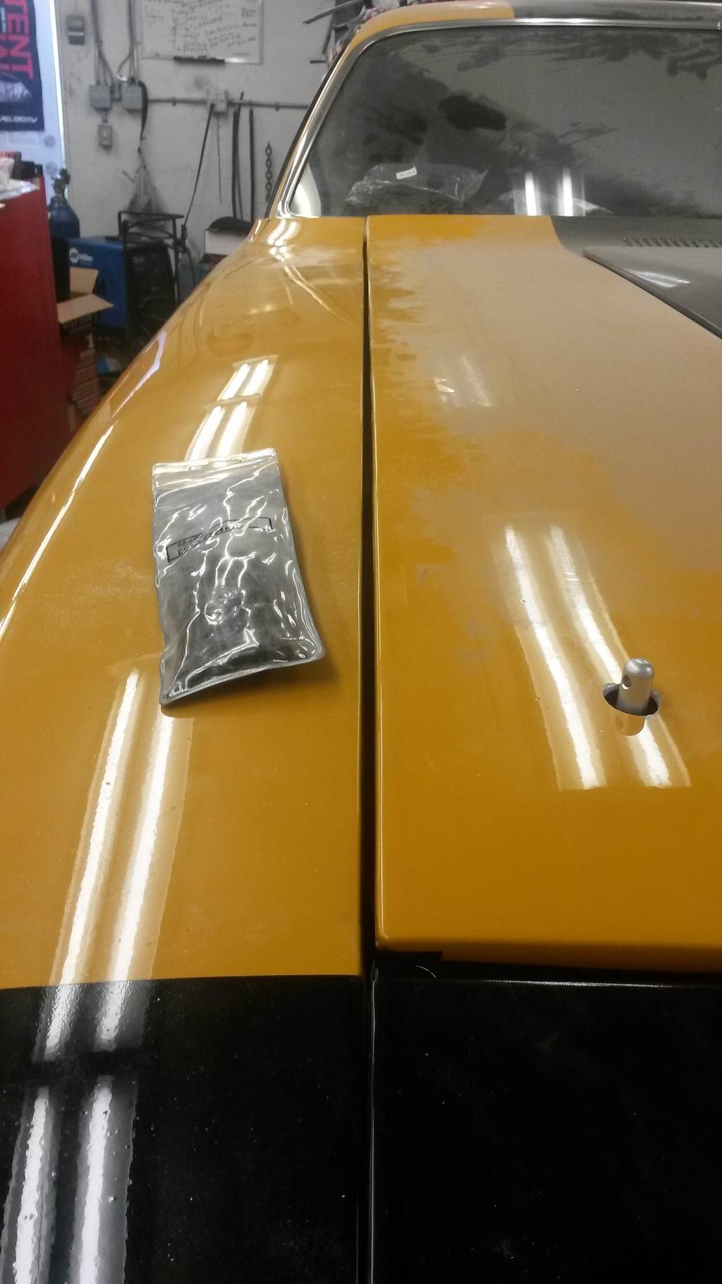
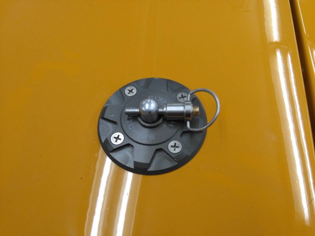
tried lining up the fiberglass hood more so the fitment is better (I give it a 7 outta 10, but what can you do) and drilling my new hotchkis hood pins:

Been working on it so much this past year my boys have gotten in on it!

found a good spot for my exterior emblems

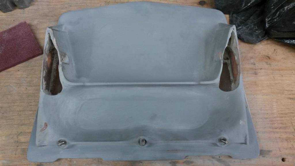
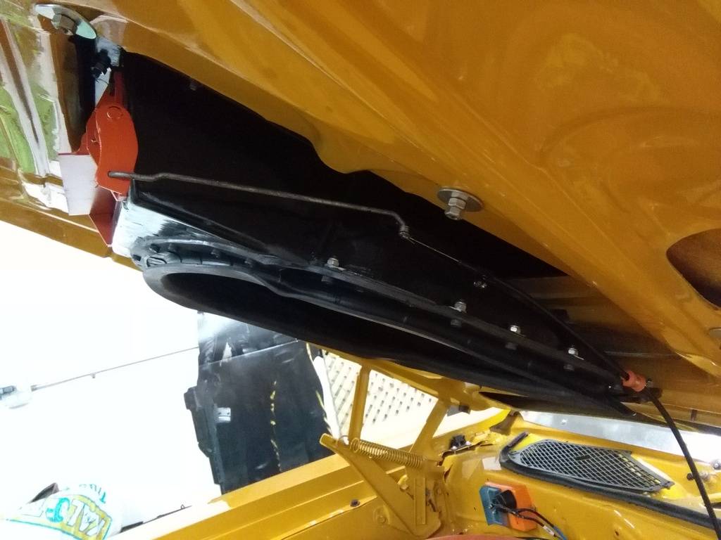
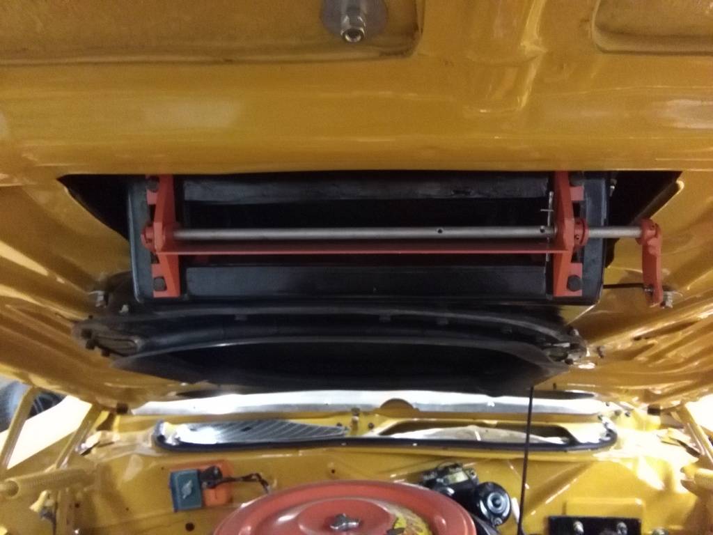
So making a functional fiberglass airgrabber hood is a PITA, I had to chop out where the arms mount, fill them with fiberglass (lots of time and layering) and cut out where the arms go again:
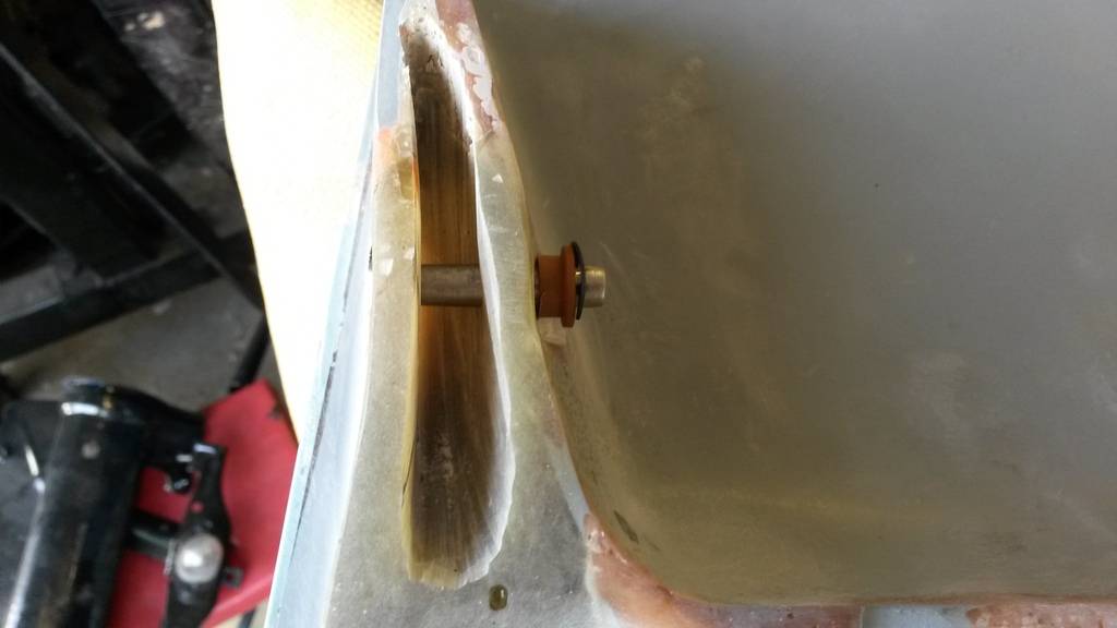
I wanted to convert this to a manual pull lever setup like the old air grabbers, so this is what I had gotten(bought at same place as the airgrabber setup ( I wouldn't recommend this, get oem)
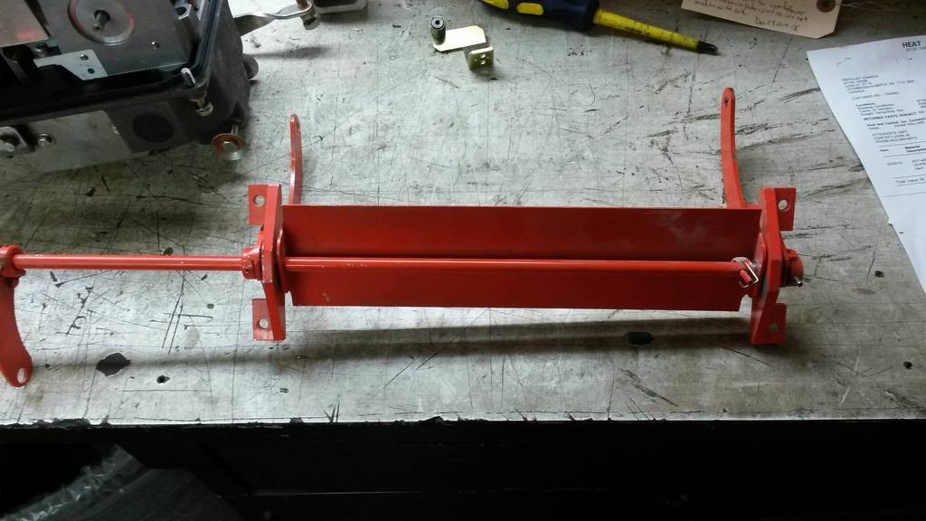
I cut the rod and flipped and welded the plate on the drivers side:
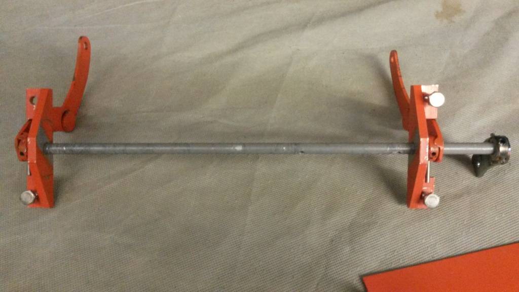
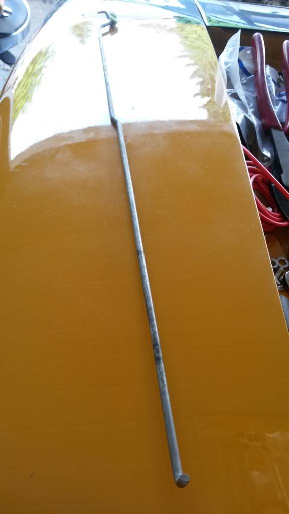
found a rod normally used inside the doors, I'm now using this as my extension rod for my airgrabber setup:
bought this cable and its what I will be using for this airgrabber:
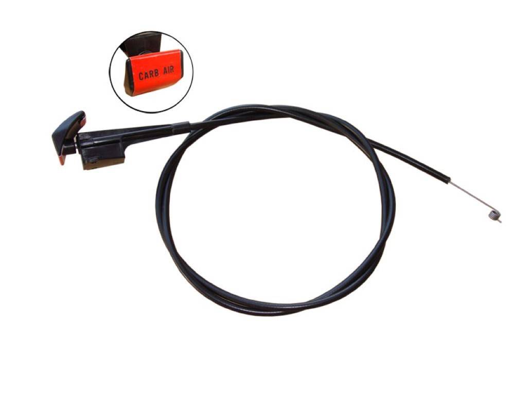
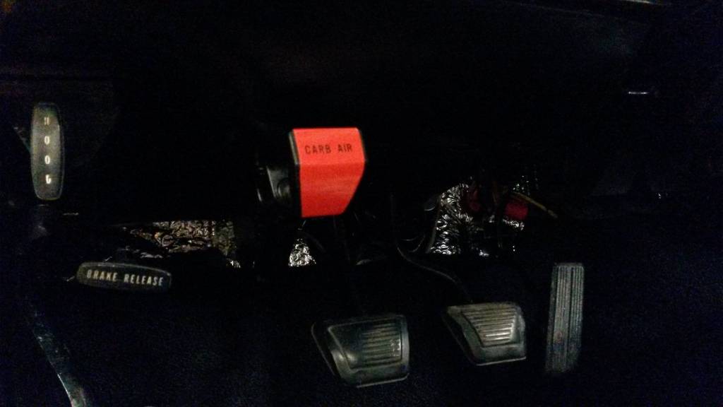
Put them together and this is what I came up with:
I mounted the the handle in the exact same spot as if you had a 71 runner with a hemi and a choke! works good too!!! wish the cable was longer but its the best I could have done for now
stay tuned! got more to come very soon as I'm ready to drive this bird!!!Build Thread!!!https://www.pro-touring.com/showthread.php?88692-1971-Speedipus-Rex&p=925864&posted=1#post925864
05-12-2016 #60 Registered User
- Join Date
- Jan 2011
- Location
- Jefferson City, MO
- Posts
- 240
Just found this thread. Love it! Subscribed.
Tags for this Thread

 Reply With Quote


