


Results 401 to 420 of 2014
Thread: Project BLUEprint, 1965 Falcon
-
10-17-2010 #401

 Registered User
- Join Date
- Apr 2009
- Location
- san diego
- Posts
- 5,101

So this is what I am thinking. I will make the bell crank threaded and tighten the bolt to the bell crank with a nut on the front side and the bolt coming from the back. The cradle will still have finite adjustment holes. But instead of being a 1/4" thick aluminum plate I will box in the cradle with a plate on the backside too. I would still have the 1" x 1" square tube as a picture frame. At the pivot mounts I will use bronze step bushings this will be the bearing surface for rotation and thrust. So the bolt will pivot with the bell crank. Does that make sense. It will work, I just need to figure out the stack up of all the pieces and make sure it will fit.
My build thread: https://www.pro-touring.com/showthre...ing&highlight=
The mustang build thread: https://www.pro-touring.com/showthre...el)&highlight=
-
10-18-2010 #402
Registered User
- Join Date
- Apr 2009
- Location
- san diego
- Posts
- 5,101
Here is my solution, I will weld in a aluminum coupling nut into the bell crank. This will be a spacer for the rodends. The bolt will be locked to the bellcrank with a jam nut on the front side. The cradle will be boxed on the backside as well. Not shown in the pictures is the spacers welded to the plates. The bronze bushing will be pressed into these spacers. Here are some drawings of my idea.
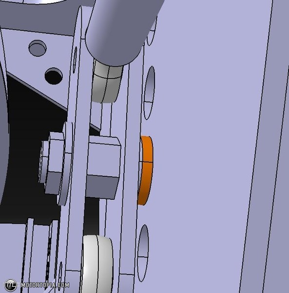
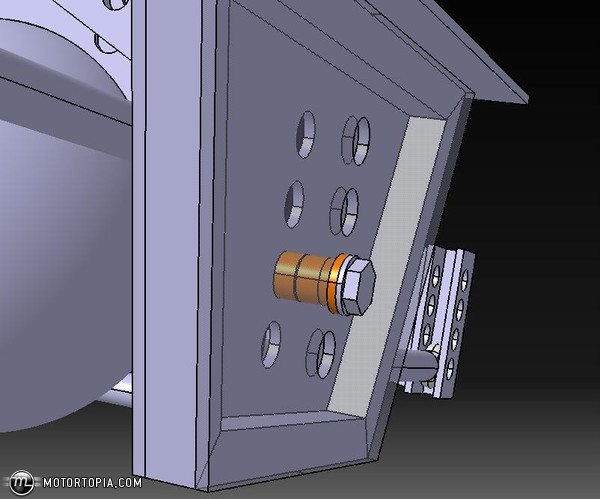
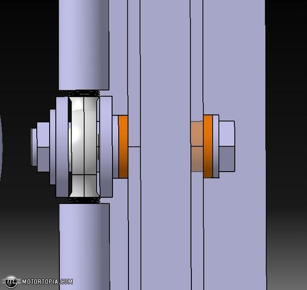 My build thread: https://www.pro-touring.com/showthre...ing&highlight=
The mustang build thread: https://www.pro-touring.com/showthre...el)&highlight=
-
10-18-2010 #403
Registered User
- Join Date
- Apr 2009
- Location
- san diego
- Posts
- 5,101
Okay, so after more thought I decided that is a bad idea. I dont want to have the bell crank threaded. Since it will always be seeing a impulse force, it will always be stressing the threads and trying to loosen and tighten depending on the rotation. So I am back to the drawing board. I think the best option right now is to make the entire cradle quickly removeable, using studs or captive nuts. another option will be to remove the coilovers and dropping the rear end out so I can pull the bolt out the front. Yet another option that I have not figured out how to do; i would make the cradle to pieces so I could remove half of it easier. Well, I guess some brainstorm session tonight.
Mabybe if I start at the car long enough it will come to me.My build thread: https://www.pro-touring.com/showthre...ing&highlight=
The mustang build thread: https://www.pro-touring.com/showthre...el)&highlight=
-
10-18-2010 #404
 Registered User
- Join Date
- Nov 2008
- Location
- TN
- Posts
- 959
Well, you could go with the theory that if you think about something else then your answer will come to you. Then you could get some work done on my front suspension set-up while your brain works on it? No? haha! Worth a try!
How about pins that hold the whole cradle in? with double shear mounting points on either side? then just slide the pins out and drop the whole thing. it only has to absorb loads on one plane right? or does it have a non-planar moment force?Benjamin
Twin Dusters
'72 Plymouth Duster "Aero Duster" project
'72 Plymouth Duster "Daily Duster" project
https://www.pro-touring.com/showthre...RO-DUSTER-quot
-
10-18-2010 #405
Registered User
- Join Date
- Apr 2009
- Location
- san diego
- Posts
- 5,101
HAHA, I know I need to start up again on your suspension geometry. From memory the stock is pretty damn good. A little more camber gain and dial out bumpsteer and you will be solid.
The watts link can see out of plan loads. (mainly lateral but some fore/aft). The for/aft is due to suspension travel that makes the watts links not parralel in plan view (looking from the top down). I wish I had CATIA on my home computer so I could be designing right now. Not just sketching on paper. Pins would work, I just want to make sure I dont have any slop in the setup.My build thread: https://www.pro-touring.com/showthre...ing&highlight=
The mustang build thread: https://www.pro-touring.com/showthre...el)&highlight=
-
10-18-2010 #406
Registered User
- Join Date
- Dec 2008
- Location
- Covina, Ca
- Posts
- 95
Would it be possible to move the watts link cradle forward? Get it as close as possible to the rear end housing and put the bell crank on the back side of the cradle, like the lateral dynamics 3 link.
Jon
-
10-19-2010 #407
Registered User
- Join Date
- Nov 2008
- Location
- TN
- Posts
- 959
Well, If you did two vertical pins, and two horizontal you would have all your degrees of freedom taken care of. And when you go to design the hole size tolerances you can just keep it on the tight side.
Benjamin
Twin Dusters
'72 Plymouth Duster "Aero Duster" project
'72 Plymouth Duster "Daily Duster" project
https://www.pro-touring.com/showthre...RO-DUSTER-quot
-
10-19-2010 #408
Registered User
- Join Date
- Apr 2009
- Location
- san diego
- Posts
- 5,101
That would work; however, that would place the axle mounts for the watts link at 8" behind the axle centerline in plan view. I dont really like that large of a moment placed on those brackets. If I can reduce the bending moment then i can keep the overall weight down. Originally Posted by jtomas801

Thank you for the suggestion! I need the ideas coming.My build thread: https://www.pro-touring.com/showthre...ing&highlight=
The mustang build thread: https://www.pro-touring.com/showthre...el)&highlight=
-
10-19-2010 #409
Registered User
- Join Date
- Apr 2009
- Location
- san diego
- Posts
- 5,101
Yes, that would work. I will think about where the split would be to accomadate a quick release. Originally Posted by Bjkadron
Right now the plan is to go back to my original design and and just make the complete cradle unbolt.My build thread: https://www.pro-touring.com/showthre...ing&highlight=
The mustang build thread: https://www.pro-touring.com/showthre...el)&highlight=
-
10-19-2010 #410
Registered User
- Join Date
- Apr 2009
- Location
- san diego
- Posts
- 5,101
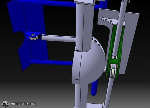
I solved the watts issues. I will draw it up tomorrow. The pivot bolt will be in double shear. Everything is more compact and better looking. The system is stronger and lighter. I am really excited about this final design. I have never seen a watts built this way. It results in 3 fasteners to be removed to make a roll center change. So nice a quick.
My build thread: https://www.pro-touring.com/showthre...ing&highlight=
The mustang build thread: https://www.pro-touring.com/showthre...el)&highlight=
-
10-20-2010 #411
Registered User
- Join Date
- Apr 2009
- Location
- san diego
- Posts
- 5,101
Here is the new solution:
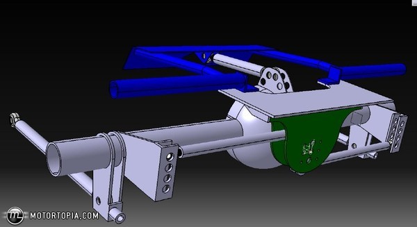
 My build thread: https://www.pro-touring.com/showthre...ing&highlight=
The mustang build thread: https://www.pro-touring.com/showthre...el)&highlight=
-
10-20-2010 #412
 Registered User
- Join Date
- May 2001
- Location
- Mesa, Az.
- Posts
- 1,435
Looks good Bryce... I likey.
Phillip
64 Studebaker Daytona Twin Turbo- http://bit.ly/1SgxQ0g
65 Cutlass F-85 - http://bit.ly/1W4lJm4
-
10-20-2010 #413
Registered User
- Join Date
- Nov 2008
- Location
- TN
- Posts
- 959
Bugger. That was my idea. Well, at least I know it was a good one haha! Looks great! Where are the three bolts?
I've been doing some modeling too. But so far all I have done is some bolts and a couple small pieces. Any chance I can get the files for the rod-ends from you?Benjamin
Twin Dusters
'72 Plymouth Duster "Aero Duster" project
'72 Plymouth Duster "Daily Duster" project
https://www.pro-touring.com/showthre...RO-DUSTER-quot
-
10-20-2010 #414
Registered User
- Join Date
- Apr 2009
- Location
- san diego
- Posts
- 5,101
Benjamin,
First, mcmaster.com has step files and IGS files for rodends and lots of other stuff.
The 3 bolts are the three columns of holes you see from the back. I am putting removeable spacers there so I can stiffen up the plates, box them together.My build thread: https://www.pro-touring.com/showthre...ing&highlight=
The mustang build thread: https://www.pro-touring.com/showthre...el)&highlight=
-
10-21-2010 #415
Registered User
- Join Date
- Nov 2008
- Location
- TN
- Posts
- 959
Oh that is AWESOME! Thanks for the tip! Originally Posted by falcon65
If you are going to do the removable spacers, why not just make the whole pivot/spacers a assembly, then just slide the whole thing up or down?Benjamin
Twin Dusters
'72 Plymouth Duster "Aero Duster" project
'72 Plymouth Duster "Daily Duster" project
https://www.pro-touring.com/showthre...RO-DUSTER-quot
-
10-21-2010 #416
Registered User
- Join Date
- Apr 2009
- Location
- san diego
- Posts
- 5,101
That would work but not very well for my plans. The bolt will thread into the back plate and be locked in with a nyloc nut. This bolt will be tighten to a small preload on the bell crank between the two plates. The bronze flanged bushing will pressed into the bell crank assembly. These will take rotation and thrust loads. The spacers are spreading the load over a larger area. There will also be steel plates bolted to the outsides of the vertical aluminum plates. I hope that made sense. Originally Posted by Bjkadron
My build thread: https://www.pro-touring.com/showthre...ing&highlight=
The mustang build thread: https://www.pro-touring.com/showthre...el)&highlight=
-
10-22-2010 #417
Registered User
- Join Date
- Apr 2009
- Location
- san diego
- Posts
- 5,101
I got all my drawings done so this weekend will be spent cutting aluminum for the watts cradle. Im getting closer!
My build thread: https://www.pro-touring.com/showthre...ing&highlight=
The mustang build thread: https://www.pro-touring.com/showthre...el)&highlight=
-
10-23-2010 #418
Rat Pack Member

- Join Date
- Aug 2002
- Location
- Waleska Ga.
- Posts
- 2,722
Very Cool cant wait to see this come together! Originally Posted by falcon65
David Sloan
If you’re suggesting sending men with weapons of war to take my weapons of war,then I’m fairly certain that’s what’s called an act of war… and the definition of tyranny.which coincidentally is the reason for the second amendment to begin with!
https://www.pro-touring.com/showthre...ght=fun+camaro
https://www.pro-touring.com/threads/...lcamino-build!
-
10-24-2010 #419
Registered User
- Join Date
- Apr 2009
- Location
- san diego
- Posts
- 5,101
Thanks David. Originally Posted by David Sloan
So I realized my job spoiled me. I have a laser cutter at work and it cuts perfect and fast. When I am at home I have to do all my own layouts and cut it out with the bandsaw, then come back finish the edges. That is time consuming, HAHA. I got all the aluminum pieces cutout yesterday, today will be used to finish them and mock it, next week get it welded and installed in the car.My build thread: https://www.pro-touring.com/showthre...ing&highlight=
The mustang build thread: https://www.pro-touring.com/showthre...el)&highlight=
-
10-24-2010 #420
Registered User
- Join Date
- Nov 2008
- Location
- TN
- Posts
- 959
Originally Posted by falcon65
You should get them to let you use the laser cutter afterhours!
Benjamin
Twin Dusters
'72 Plymouth Duster "Aero Duster" project
'72 Plymouth Duster "Daily Duster" project
https://www.pro-touring.com/showthre...RO-DUSTER-quot
-

 Reply With Quote