

Results 1 to 20 of 22
Thread: 1989 Chevrolet C1500
-
11-12-2024 #1
 Registered User
- Join Date
- Jun 2019
- Location
- Nashville, TN
- Posts
- 24

1989 Chevrolet C1500
Hey folks,
My name is Jimmy King, and I am here to document the build of my 1989 C1500. The truck is about finished and over the next few posts Im going to write in high detail about the truck, my build process and fabrication, and why I did things the way I did. The goal with this truck is to run autocross and some road course stuff this next year.
To give some background on myself, Ive been building cars in some capacity for roughly 15 years. My dad and brother are great influences in that and my passion started in more traditional hot rods as thats what they were into. Fast forward through college where I received my degree in mechanical engineering, I became more interested in racing and what that entails. Engineering school set me up with some great tools and the knowledge to look at the components of cars in a more objective way and design them as such.
I hope this post will spark some good discussion and will help me improve when moving into the development phase of this truck and chassis.

PART ONE: Front Chassis, Suspension, and Brakes
I took a lot of inspiration looking at TA2 and circle track cars, and there is a big crossover between the two as a few manufacturers build both. In particular, I found a brochure for the Howe TA2 chassis and they had a color-coded picture that labeled all the tube sizes on the chassis. Howe, at some point, worked with GM on some destructive testing of their chassis which sold me on the design. Theres a technical paper floating out there about this test.
I had worked in CAD for a few months to get the design correct. A lot of simulation with suspension/steering geometry and tire clearance. Running a 345 proved to be a decent challenge. There are compromises to everything, and at some point, I needed to start building.
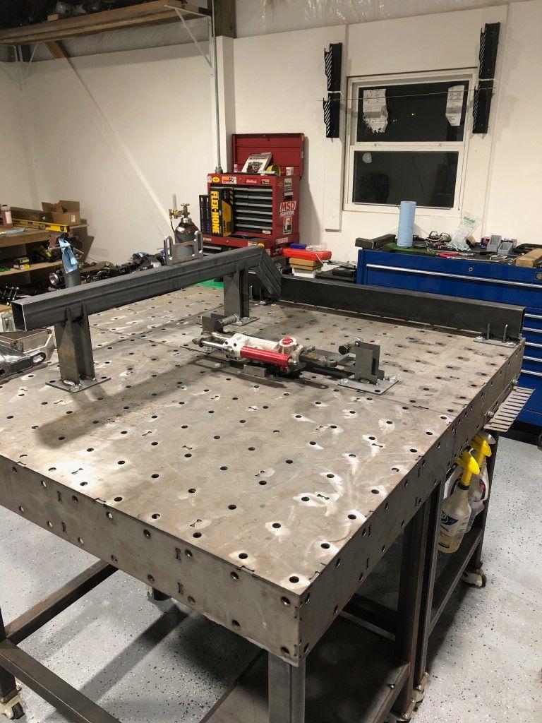
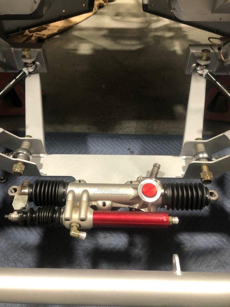
I designed around a used Woodward Steering rack that I found for a few hundred dollars online. I dont find any particular problems with steering boxes, but if I was building a chassis from scratch, this made the most sense. I can also swap parts to achieve a wide range of steering ratios.
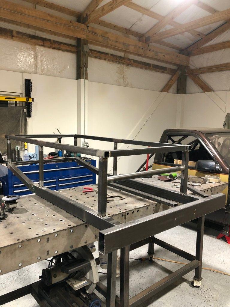
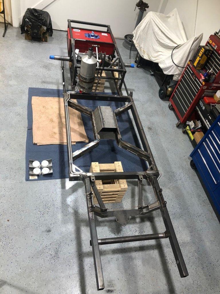
I built many fixtures to place all the tubes and maintain accuracy. I love building this way because components only fit one way. The crossmember closest to top of this photo eventually had a chunk cut from the center to accommodate the engine and transmission. I kept it intact until after the entire chassis was welded together to reduce warping.
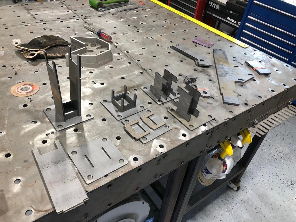
I 3D printed guides to mark out the coped profiles of each tube. This saved a lot of time as I could be working on other things while the part printed. These guides also took the guess work out once I started cutting.
This is the passenger side where the lower control mounts. The front most plate would later be trimmed slightly to clear the fittings on the dry sump oil pump.
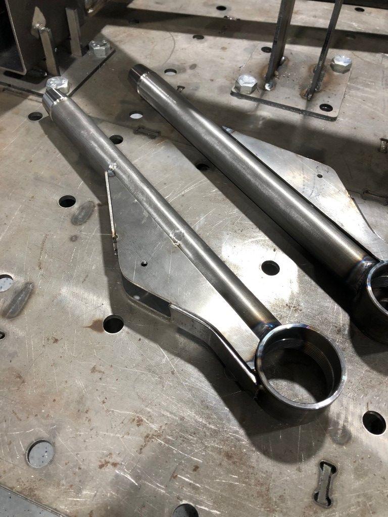
These lower control arms are all chromoly. I bought the ball joint cups to fit the K727 Chrysler ball joints. This will be an area for tuning as there are several companies that make this style ball joint in various stud lengths.
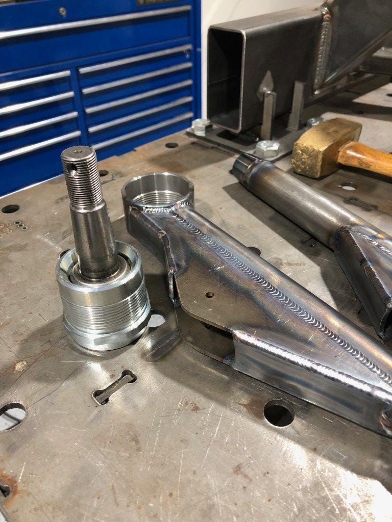
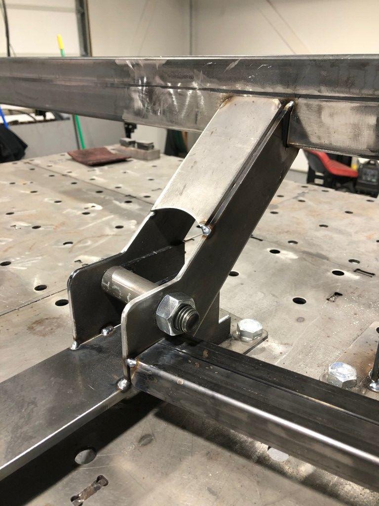
The small hole would later be drilled to accept a ¾" bolt. The lower control arm assembly is a trailing arm style, where a solid rod EYE is placed between the plates on the arm, and a rod end mounts back at the chassis.
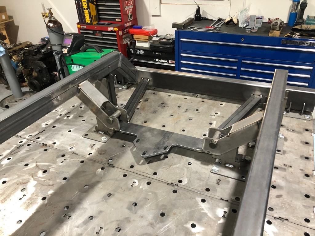
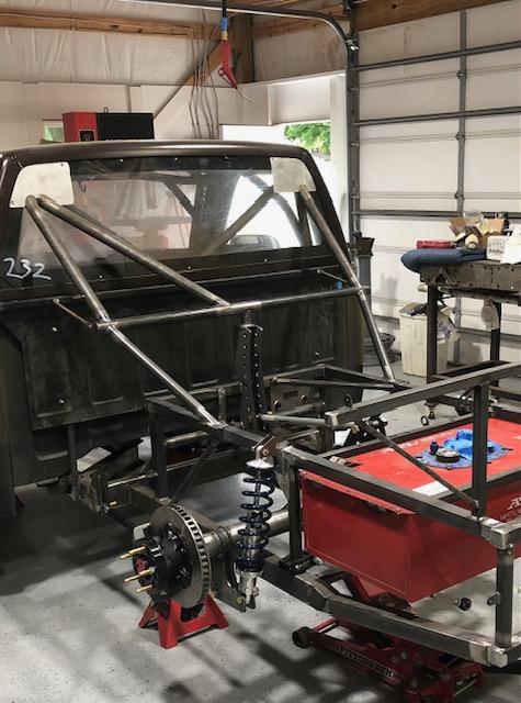
This picture jumps a way ahead, but it illustrates how the lower control arm assembly resides on the chassis.
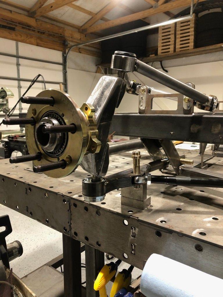
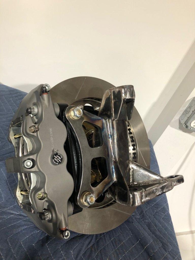
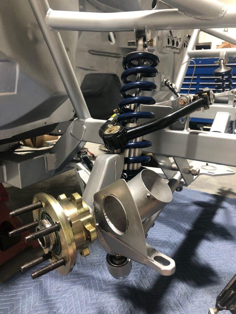
This was an early mockup with upper controls arms that I had built. Later on, I had some clearance issues and bought some upper control arms that are off the shelf and come in many different geometries. The upright is the TA2 upright from Port City Racecars. They run 2 bearings on both the inside and outside. I used Coleman hubs in 5x4.75. The pin is so big that I dont think pad knockback will be an issue. (NOTE: the rod EYE is missing from the trailing arm. I didnt have one yet so a rod end sits in place.)
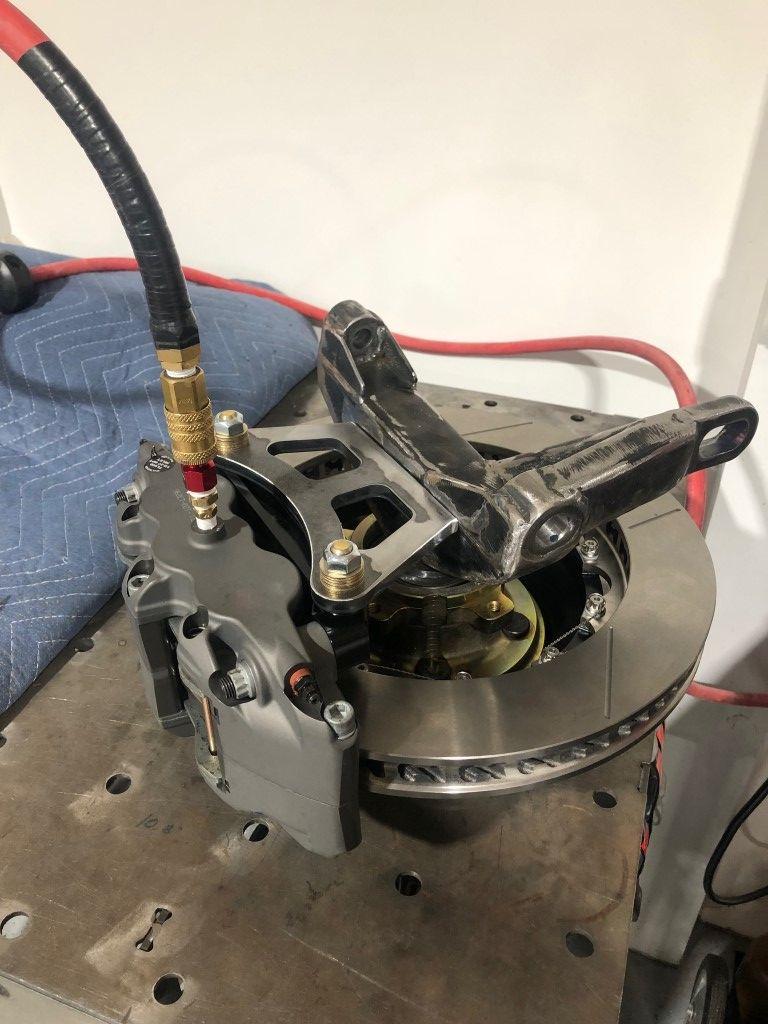
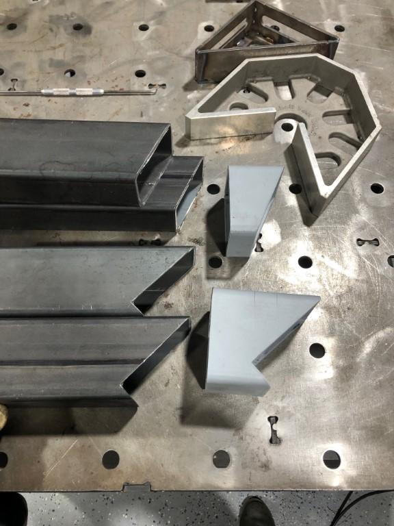
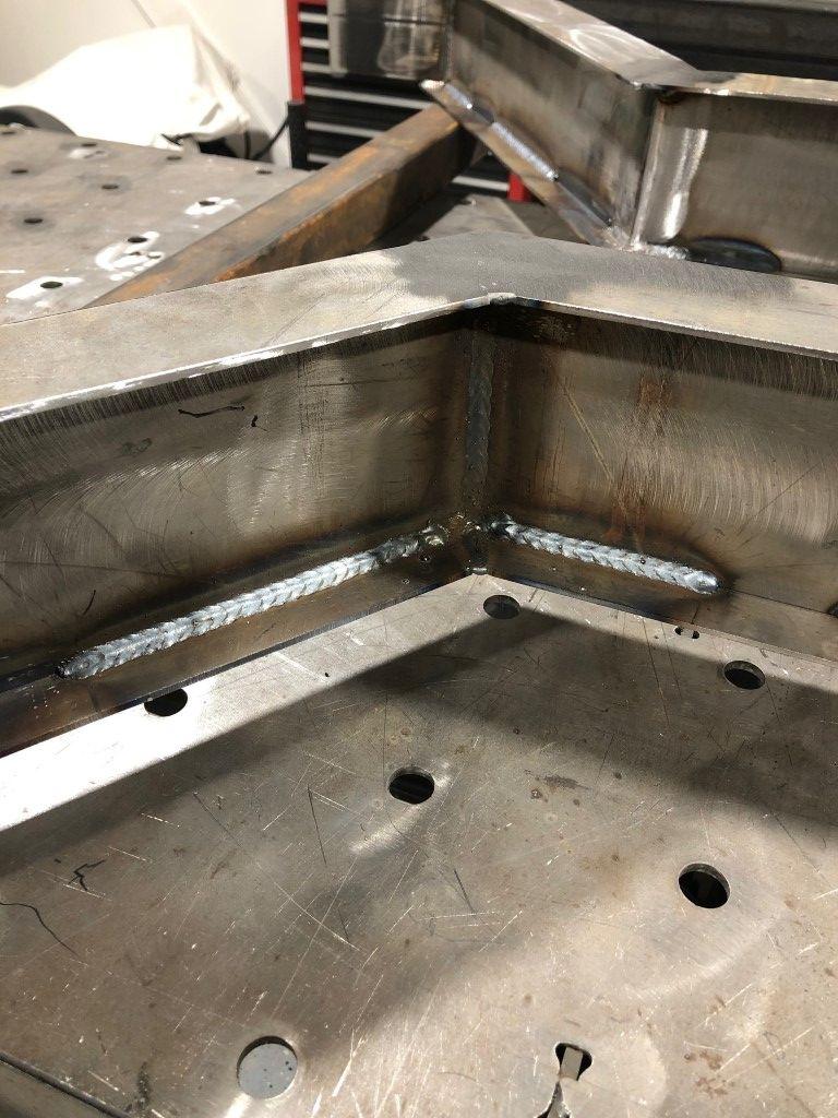
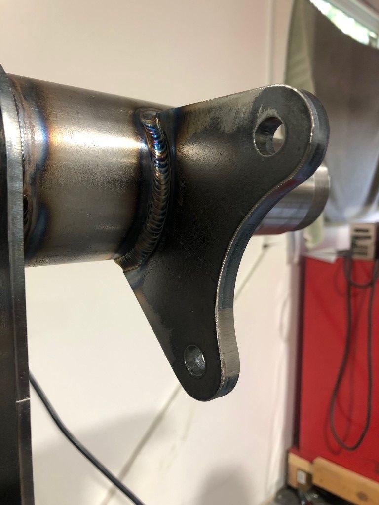
I purchased the uprights less the caliper brackets as circle track cars run a fairly small front disc. I 3D printed an initial bracket prototype, confirmed fitment, then sent the file to the laser cutter. It is 3/8 thick. I adapted my compressor hose to the caliper in order to clamp the disc and ensure a robust placement while I welded.
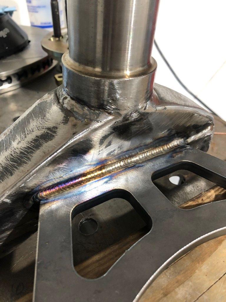
I did two passes per side as the material is thick and wanted to ensure I had a good fillet in there. Gussets were added later.
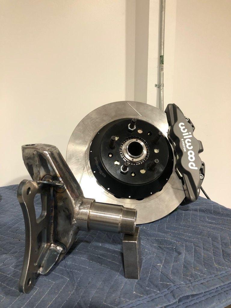
Final product.
I leave it at that for now. Next up will be the remaining sections of the chassis and rear suspension. Thank you for reading.
Jimmy
-
11-13-2024 #2
Registered User
- Join Date
- Apr 2015
- Posts
- 95
Wow really nice fab work.!Following along
-
11-15-2024 #3
 Registered User
- Join Date
- Aug 2017
- Location
- PC Beach, FL
- Posts
- 33
Thanks for sharing the build here Jimmy. I have seen some posts on socials but prefer this format much better.
What are the advantages of that type of LCA vs a rigid a-arm? Also, I am having a hard time visualizing where the spring/shock will mount in that configuration.
2000 Silverado RCSB
Built 6.1L / Kenne Bell 2.8L / 4L80E / Suspension
-
11-15-2024 #4
 -Moderator/Sponsor-
- Join Date
- Apr 2001
- Location
- The City of Fountains
- Posts
- 16,117
Fancy fabrication work! Looking forward to more updates.
Andrew1970 GTO Version 3.0
1967 Cougar build
GM High-Tech Performance feature
My YouTube Channel Please Subscribe!
Instagram @dr__efi
I deliver what EFI promises.
Remote Holley EFI tuning.
Please get in touch if I can be of service.
"You were the gun, your voice was the trigger, your bravery was the barrel, your eyes were the bullets." ~ Her
-
11-16-2024 #5
Registered User
- Join Date
- Jun 2019
- Location
- Nashville, TN
- Posts
- 24
 Originally Posted by Big_KID

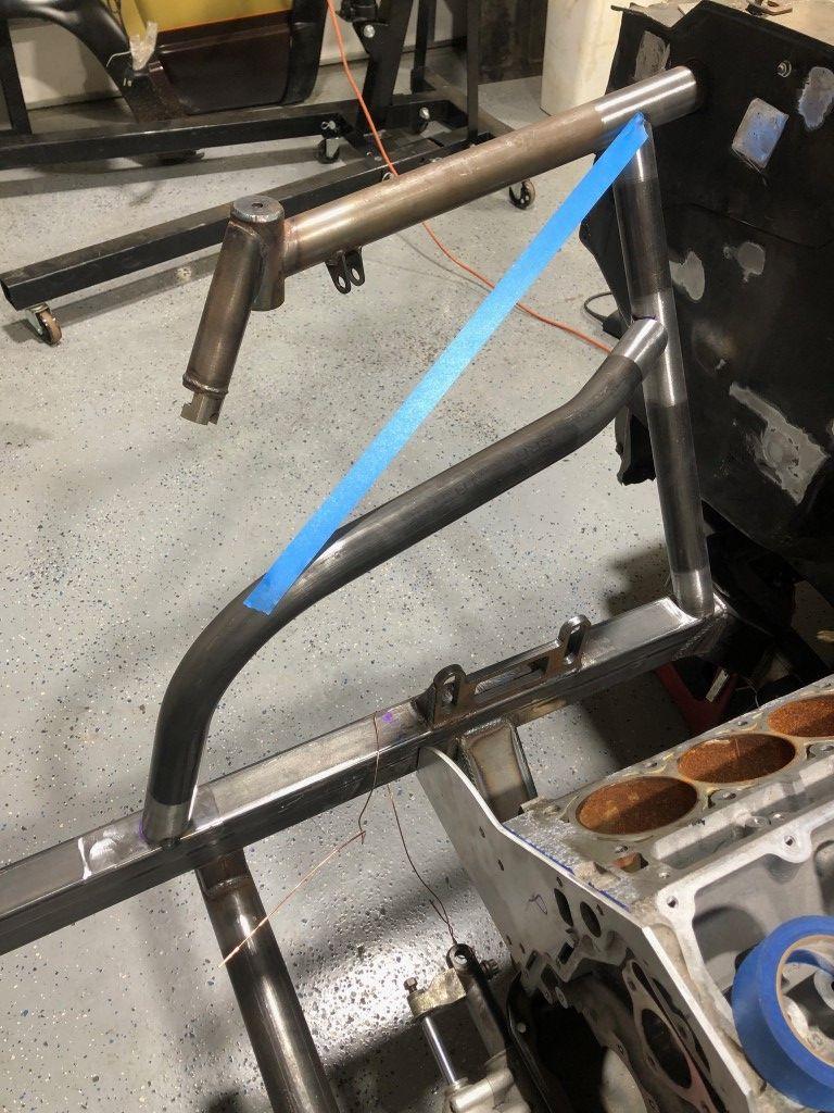
I don't think I had enough pictures to illustrate this the right way. Once everything is bolted tight, it acts as a single LCA like normal. Rod eyes don't have rotation on any axis. The reason I went this route was for tire clearance. I pushed the lower ball joint farther out toward the wheel, and with a normal "A-arm" I would have hit the wheel on the arm at high steering angle. In the picture below, the faint red line shows how tight it would be if I had that back tube near the ball joint rather than offset from the ball joint. Hope this helps!
-
11-18-2024 #6
Registered User
- Join Date
- Jun 2019
- Location
- Nashville, TN
- Posts
- 24
PART TWO: Final Chassis and Rear Suspension
To get started, Ill explain a few more background details. I forgot one huge driver behind my desire to build a chassis for this truck: ground clearance. These trucks can be lowered quite a bit without much issue, but I did find the limit for the stock GM chassis. At one point I had a truck with about 4 ground clearance to the chassis and that puts the rocker panels at about 6. Thats not low enough for my goals with this truck. Having the chassis as the limiting factor felt silly to me as there was plenty of room adjacent to the rocker panels to have a tall frame rail and be flush with the rocker itself. To lower the CG another 2 is a huge deal and I had to find some way to do it. However, I knew that lowering a stock chassis even more than it already was would make the front suspension geometry suffer even more.
A few ideas popped in my head to remedy that without building a chassis from scratch. The best idea that I do think could work would be chopping off the front stub on the stock chassis and then building a new one to fix the shortcomings of the stock geometry. To solve the ground clearance problem, I thought that one could cut the main frame rails of the chassis from 6 tall to 4 tall and keep the chassis flush with the rockers. While I think that idea could work great, I still think going for a full chassis made the most sense in this case.
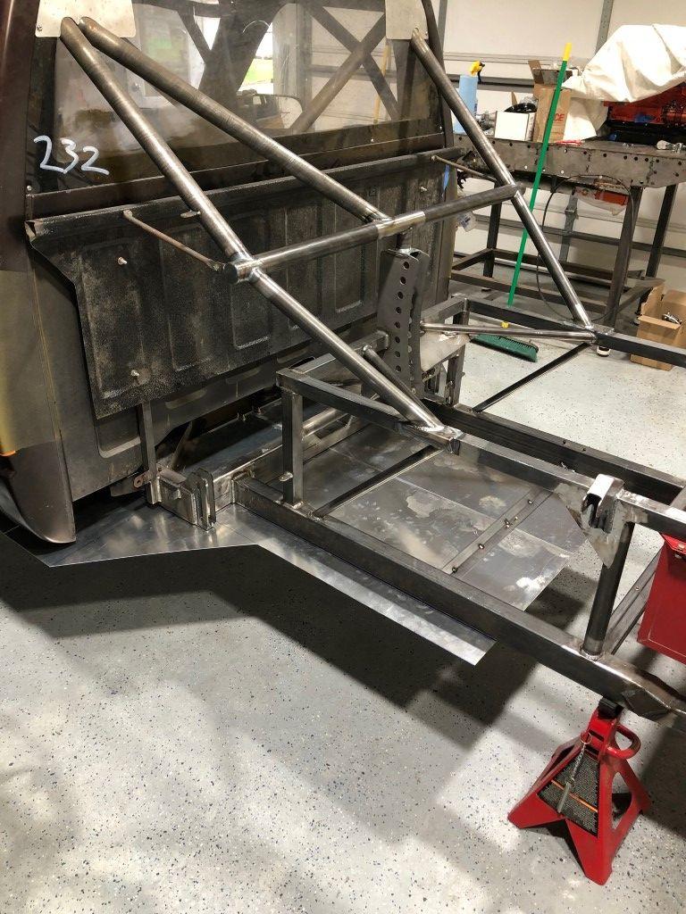
I opted for rectangular or square tubing to build the bulk of the chassis with some round tubing thrown in. For the most part, I find that tubing with flat sides much easier to build with. I did some calculating to find what sizes square tubing would have equivalent strength to specific sizes in round tubing. The kick up at the rear would allow for a diffuser and make some room for a jack under the axle.
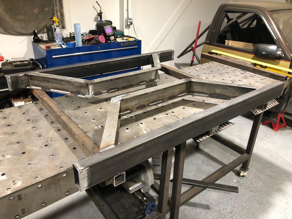
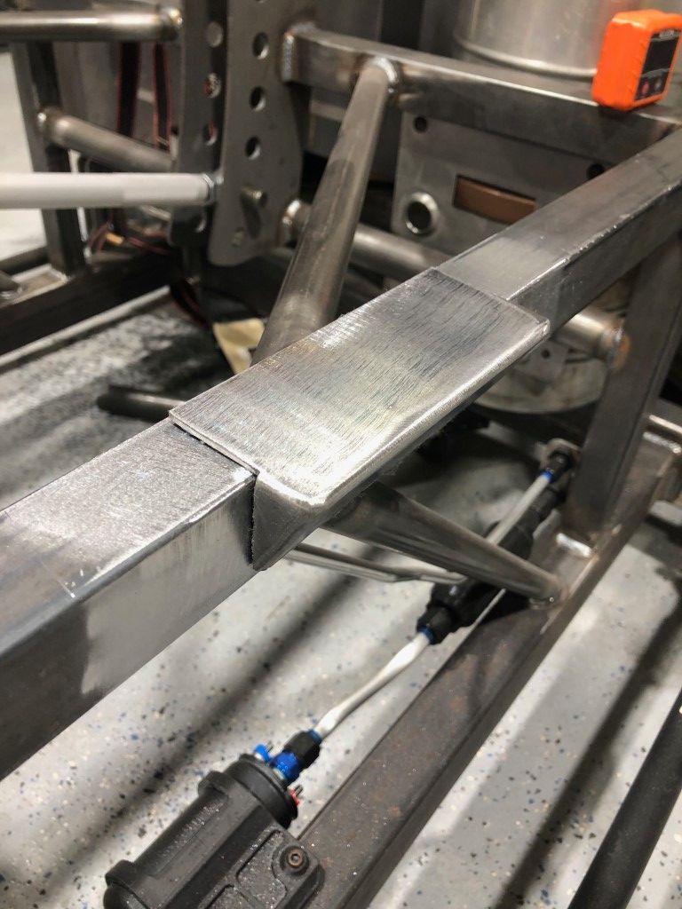
The center section tucked up next to the rockers very well. 2x4 tubing used on the perimeter and a home made I-beam (.120 plate) for the interior.
I chose not to weld the entire length of these seams, and instead welded several long stitches.
I made a tunnel of sorts to bridge the I-beams at the center of the chassis. This is where I would eventually make some big changes on the fly due to a few overlooked details. More on that later.
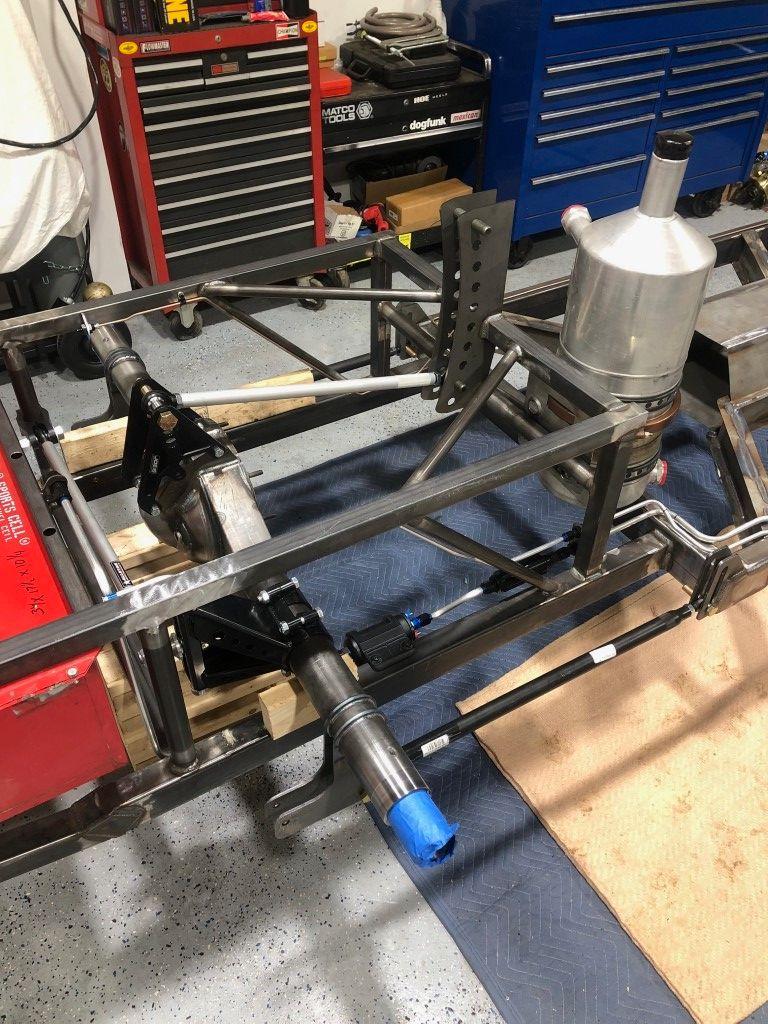
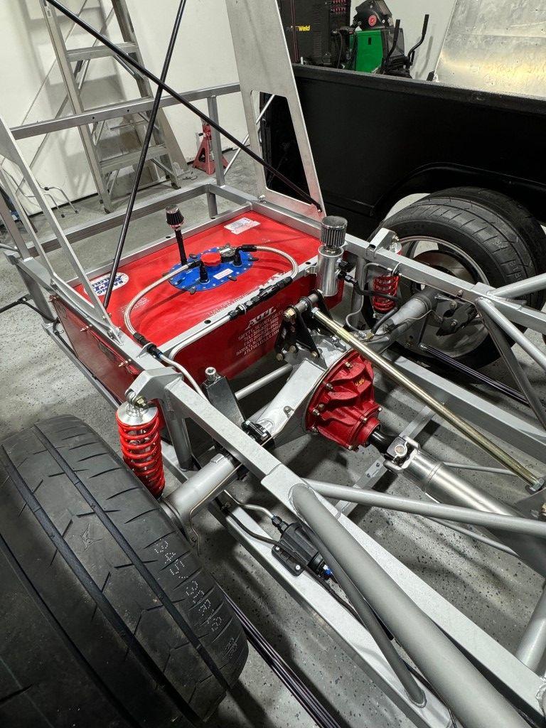
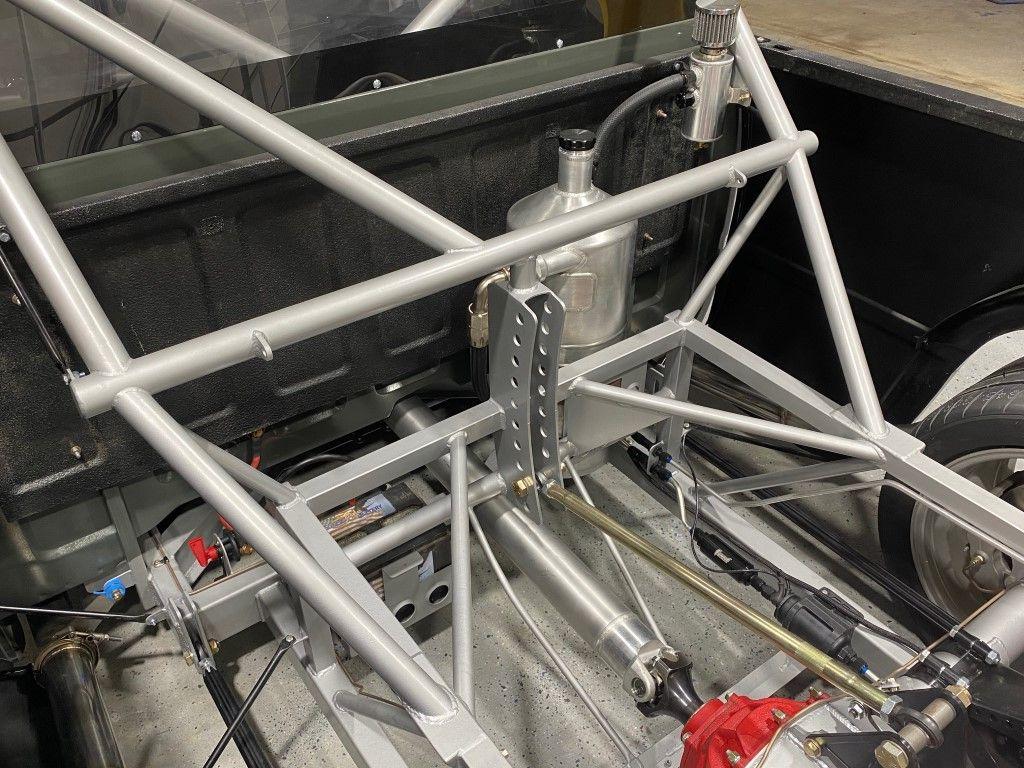
To get to the rear suspension mockup stage meant hitting a big milestone for me. Articulating an axle in real life felt like huge progress. The chassis-side upper link mount has a lot of holes well above where a solid link would bolt in. I will run a decoupled top link at some point and wanted to make sure I had the provisions in place. The deceleration link will eventually bolt into one of the upper holes on that mount. The chassis-side lower link mounts are slotted and will give more than enough adjustment range.
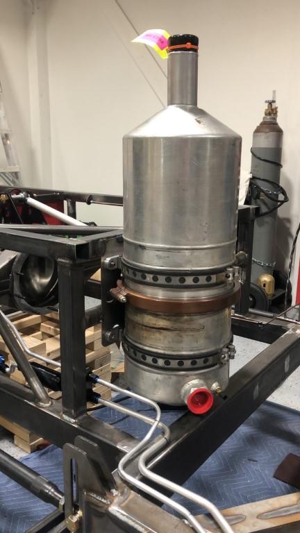
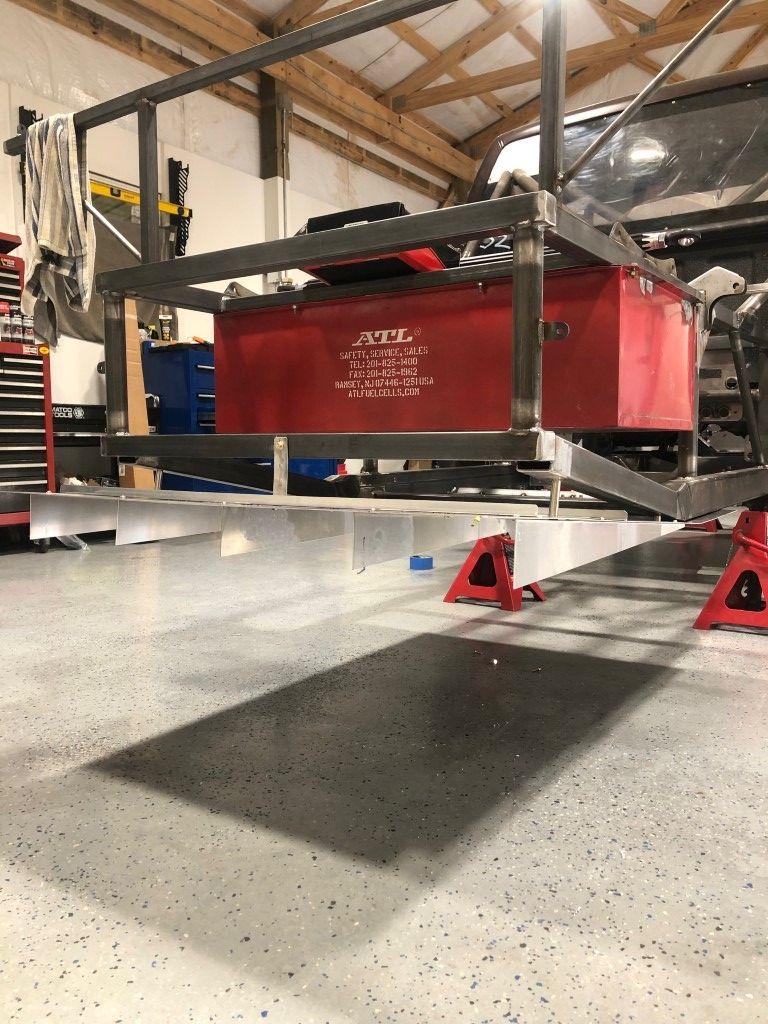
I found this used dry sump tank for about 250 or so. This will hold 5 gallons, although I will probably run around 3. There are a lot of used race parts out there online and would encourage people to take a look. Many of these parts are in fine working order, and just get put to the side as race teams close their doors or opt to run parts with less miles on them.
The axle bracket is basic. Just a couple adjustment holes. This is a full floating housing. More on that later.
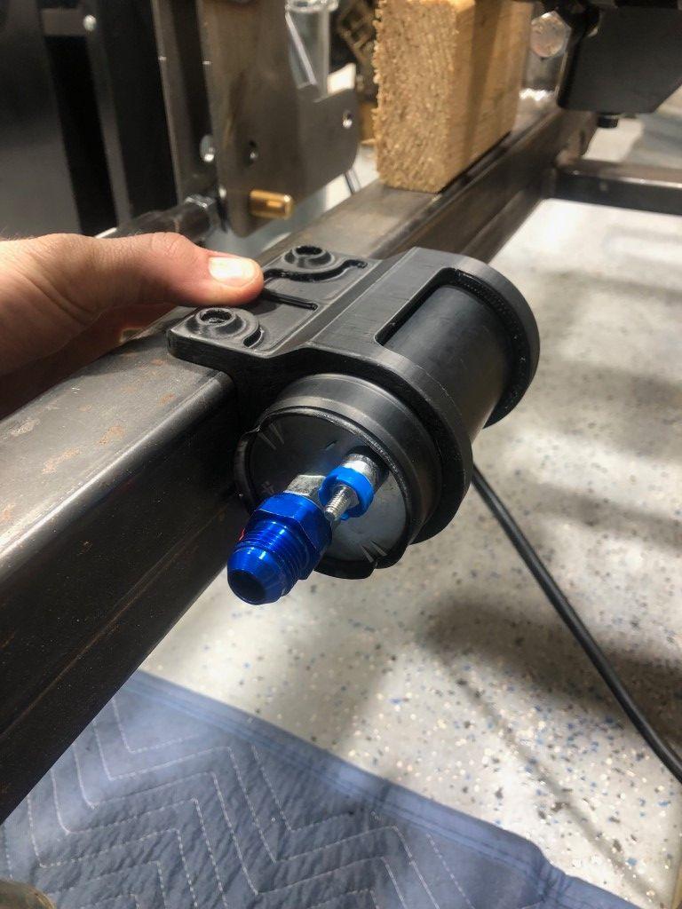
I 3D printed this housing for my fuel pump. I wanted to leave as much of the surface exposed as possible to increase air flow around it, although there should be a lot of air getting tossed in this area anyway and shouldnt be of much concern.
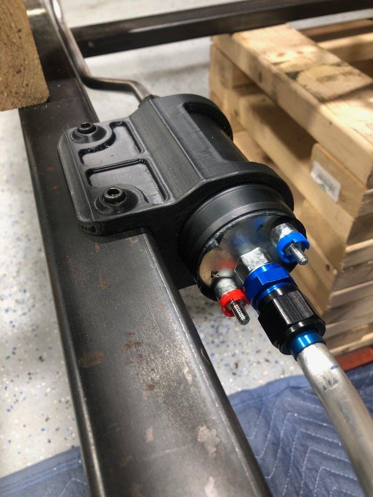
I used rivet nuts on the chassis and ran two bolts down to mount the pump housing. To allow the housing to sit flush, there are counter bores on the mounting face of the housing for the rivet nut flanges to sit into.

These weld on brackets for 9 inch housings are neat. They mimic the bolt pattern you would find on the side bells of a quick change and give tons of options for the upper link mount itself. Tall, short, setback mounts are all easy to find.
Two tig passes on these caliper brackets as well. ⅜ thick. Lateral gussets added later.
I made these landing pads for the cage to integrate onto the chassis. I wanted the chassis bracing and cage to meet at a node, creating a strong connection point.
Thanks for reading!
Jimmy
Instagram: jimmer_king
-
11-18-2024 #7
 Registered User
- Join Date
- Sep 2009
- Posts
- 2,951
Love all of the fabrication! Looks great, can't wait to see more.
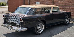
1955 Nomad project LC9, 4L80e, C5 brakes, Vision wheels
1968 Camaro 6.2 w/ LSA, TR6060-Magnum hybrid and etc SOLD
1976 T/A LS1 6 Speed, and etc. SOLD
Follow me on Instagram: ryeguy2006a
-
11-18-2024 #8
 Registered User
- Join Date
- Nov 2018
- Posts
- 944
Very nice, wish I had those fabricating skills. Looking forward to updates.
-
11-19-2024 #9
 Registered User
- Join Date
- Jul 2024
- Location
- SE Michigan
- Posts
- 30
Very nice work! Are the rear LCA mounts slotted vertically? What locates them?
-----------‐-‐---------------------------
1970 Buick Skylark Build
-----------------------------------------
-
11-19-2024 #10
Registered User
- Join Date
- Jun 2019
- Location
- Nashville, TN
- Posts
- 24
Thank you! Yes they are slotted vertically. Nothing to locate them. I just set angle and tighten the bolts down. This is pretty common on circle track stuff for both upper and lower. Originally Posted by carter_eng_fab
Instagram: jimmer_king
-
11-20-2024 #11
Registered User
- Join Date
- Jun 2019
- Location
- Nashville, TN
- Posts
- 24
PART THREE: Cab and Chassis Integration and Miscellaneous Fabrication
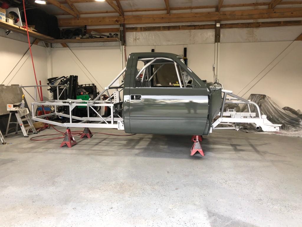
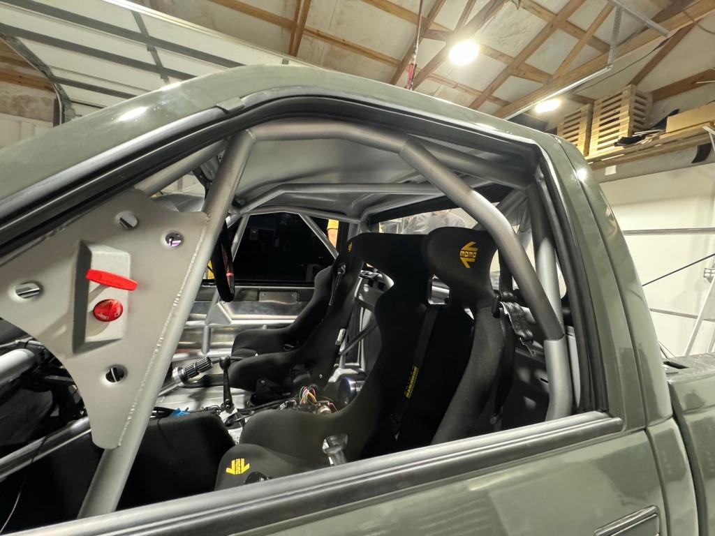
The challenge in uniting the cab and chassis was dealing with part of a roll cage that had already been built. I did have some freedom in deciding the fore and aft location of the cab as the front suspension has some adjustment range and the rear suspension could be easily changed by choosing shorter or longer control arm lengths. Full CAD models of the cab would have helped in this instance, but the time and cost there couldn’t be justified. After I decided on cab location, it was time for a test fit.
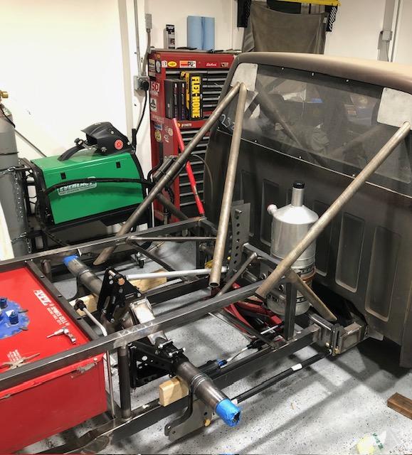
Here was the first attempt. The cab mounts themselves were in the correct positions relative to each other. At this stage I just needed to make sure there were no areas of conflict with other components. I did not move the cab from this first position and proceeded to integrate the roll cage and the chassis.
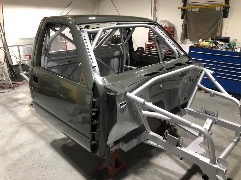
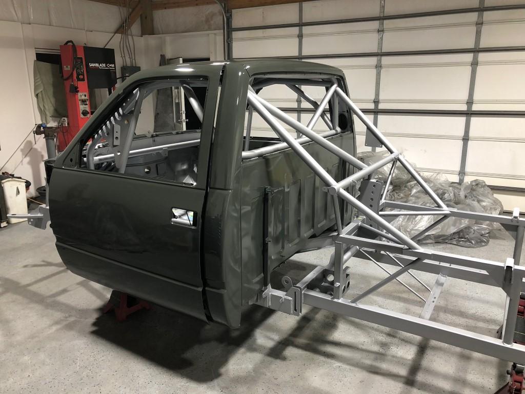
Here is the final result. The cage is 1.75” x .095” DOM and the crossbar above the upper link mount is the same. The bars going to the chassis are 1.50” x .120”. I did this because the smaller diameter gave more area to weld on the landing pad. Notching the roll cage tubes that were stationary is much harder than when I can hold the tube however I want in my hand or on a work table. Keeping that crossbar level and adjusting three tubes to be at the same distance from the chassis took time.
I had been unsure about the front end and, to be honest, felt intimidated at the time. The straight bar at the top of this photo is the original bar coming through the firewall. I had the intention of mounting the coilovers to some area of the cage structure rather than having a chassis mount like you see on stock/aftermarket chassis’. That meant having a bar much lower than the original. To achieve this, a more vertical bar up against the firewall would allow a horizontal bar to sit lower, eventually providing a spot for a coilover mount.
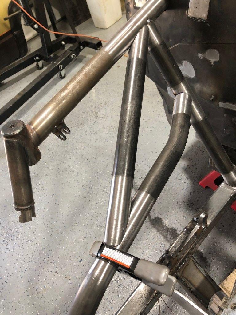
Triangles are strong. This substructure here provides some needed rigidity into the front end. I love the look of tubes with distinct lines where the mill scale is sanded off and ready to be welded.
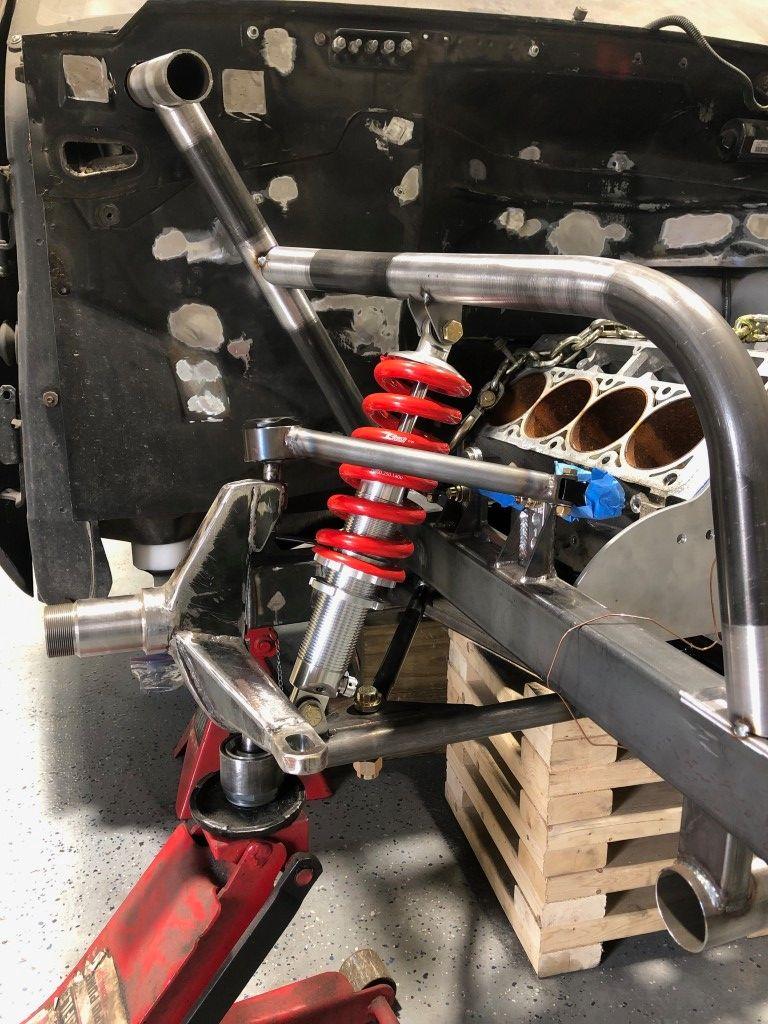
Initial shock mount mockup. It’s pretty easy to make one side, but the hard part is making the other side symmetrical. Note how close the lower shock mount is to the ball joint. I had a goal of having the best motion ratio possible within the space available. The OBS lower control arm put the coilover less than half the distance to the ball joint, creating a poor motion ratio.
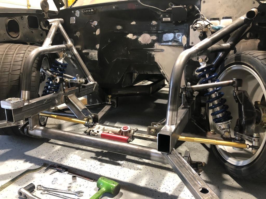
After mirroring the other side, I installed all suspension and steering to do my checks.
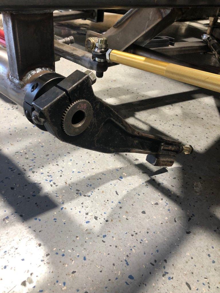
The sway bar setup for this truck consists of all used components. I found a Schroeder bar and Schroeder arms online for about 200 total. Race grade parts for cheap? Yes please. I intentionally designed the front chassis and suspension to accept a standard stock car sway bar. Sway bars are an essential tuning tool and I wanted to give myself the most options possible. 1 ¾” 48 spline x 37 ½” long is the standard. There are hundreds of options to choose from and simple to swap. Even better, there are a bunch for sale online at low cost.
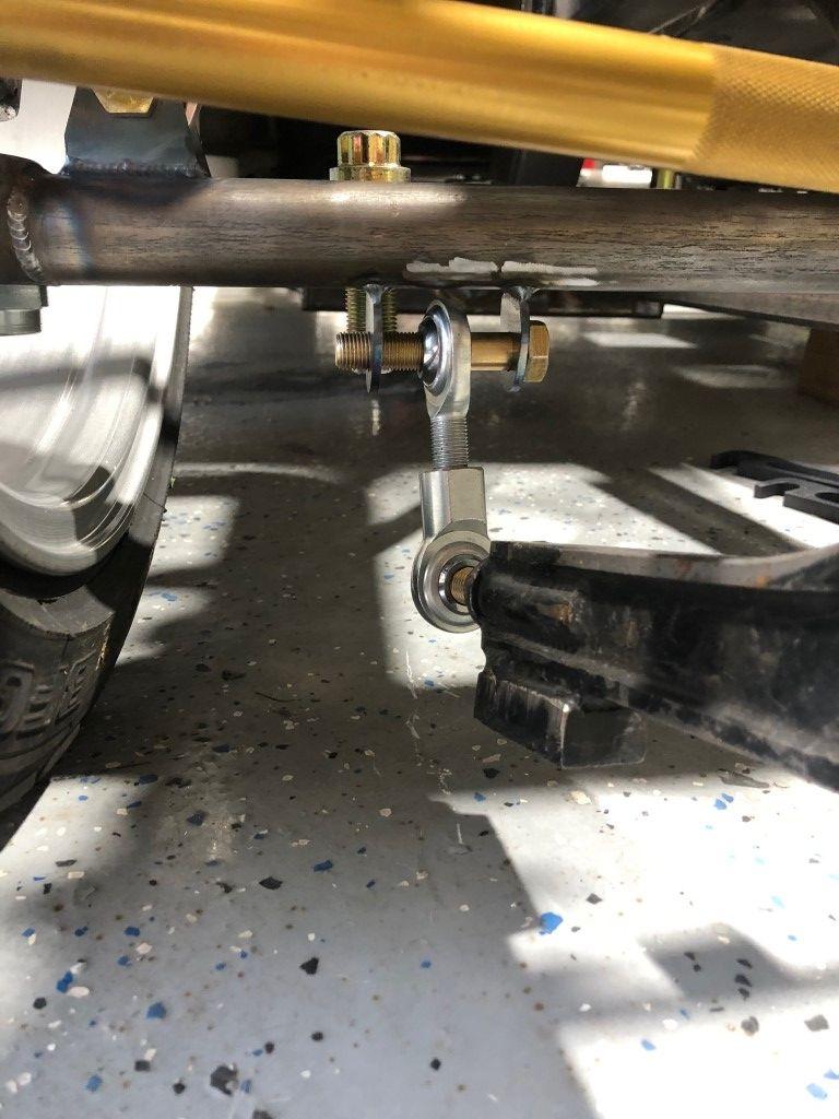
The arm is very close to the ground and has a drag block to take a hit. It is close to the tire so I’m not too concerned as the sway bar tracks with suspension/tire movement over bumps and such. There is a chance I will relocate the link mount to the upper control arm at some point. I’ll have to do some testing first to see what I like/dislike.
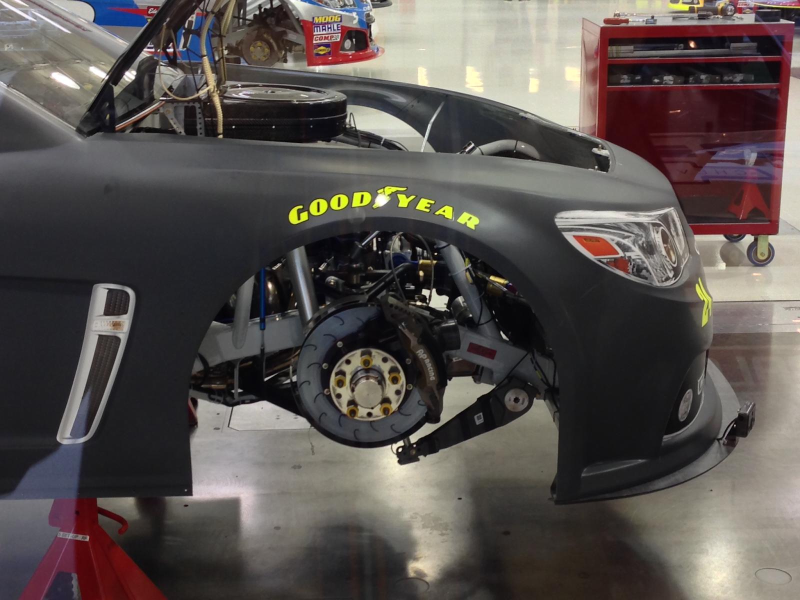
For reference, I believe this is either an Xfinity car or the previous generation Cup car. The sway bar arms are very close to the ground.
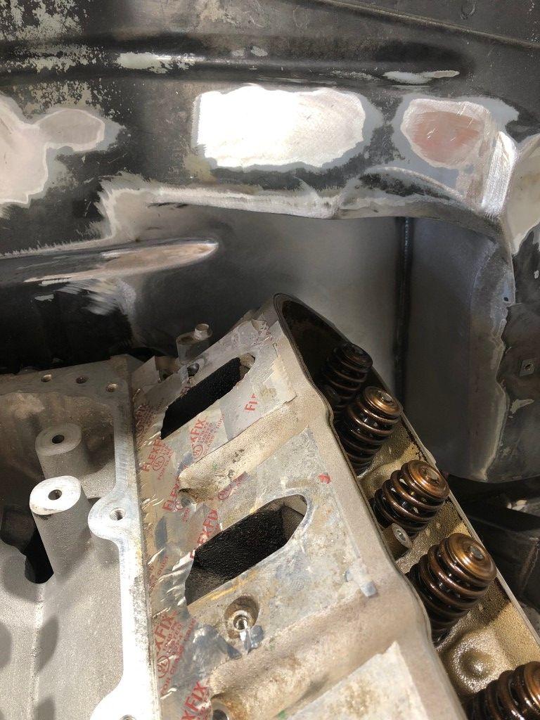
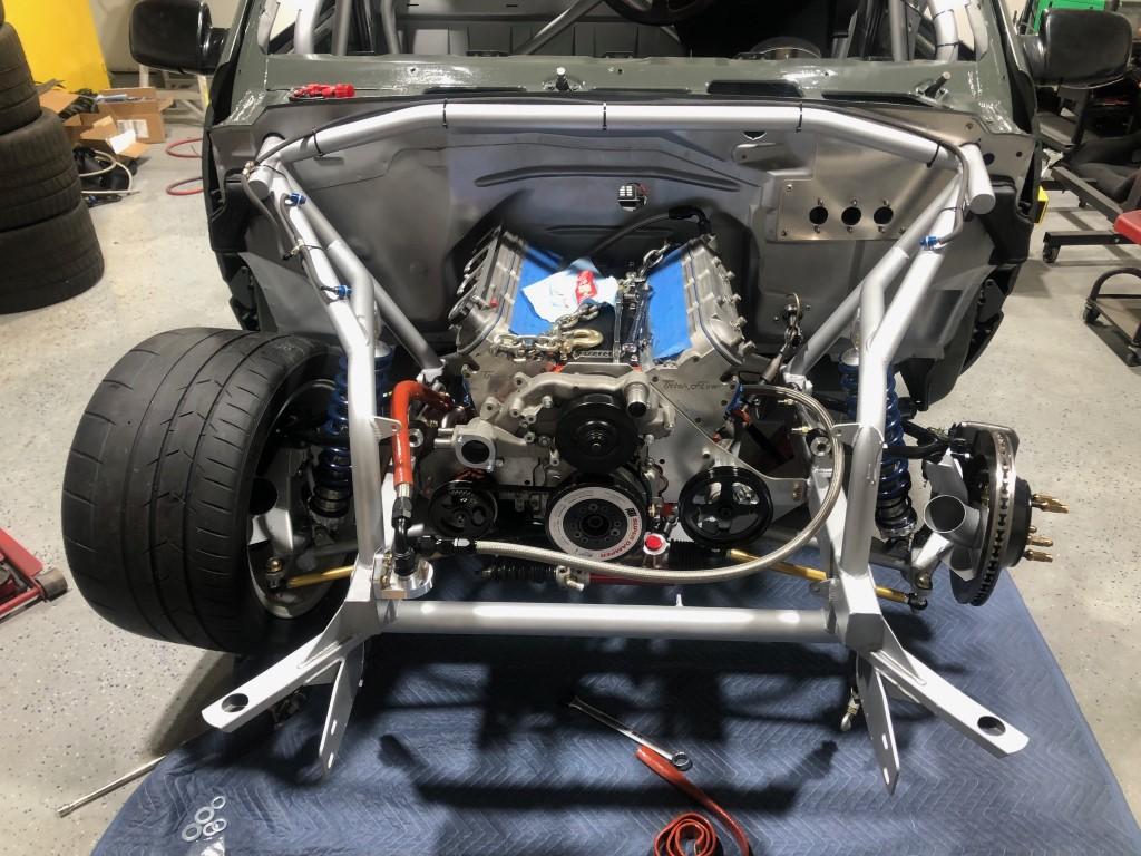
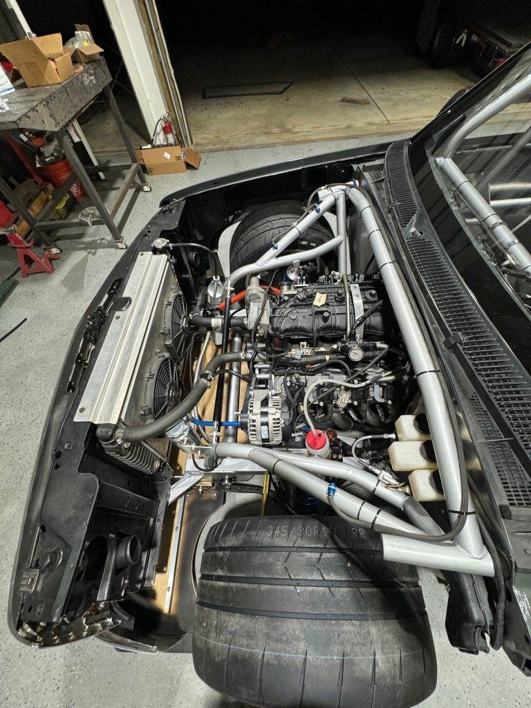
Some of the pictures above had the engine in place already and I’ll cover that now. The engine has been pushed back 2 inches (I think). I don’t know exactly but I didn’t have the desire to push the engine way back into the cab. I know people have doghouses to make engine maintenance easier, but I still didn’t want to deal with that. I moved it some and only required minimal firewall modification to make it work.
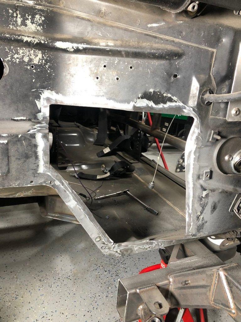
The driver side head was the first to make contact so I cut this section out. The throttle pedal mounted here as well. I knew I would have a DBW pedal and found the CTS pedal to be slim enough that I could figure out some way to mount it later.
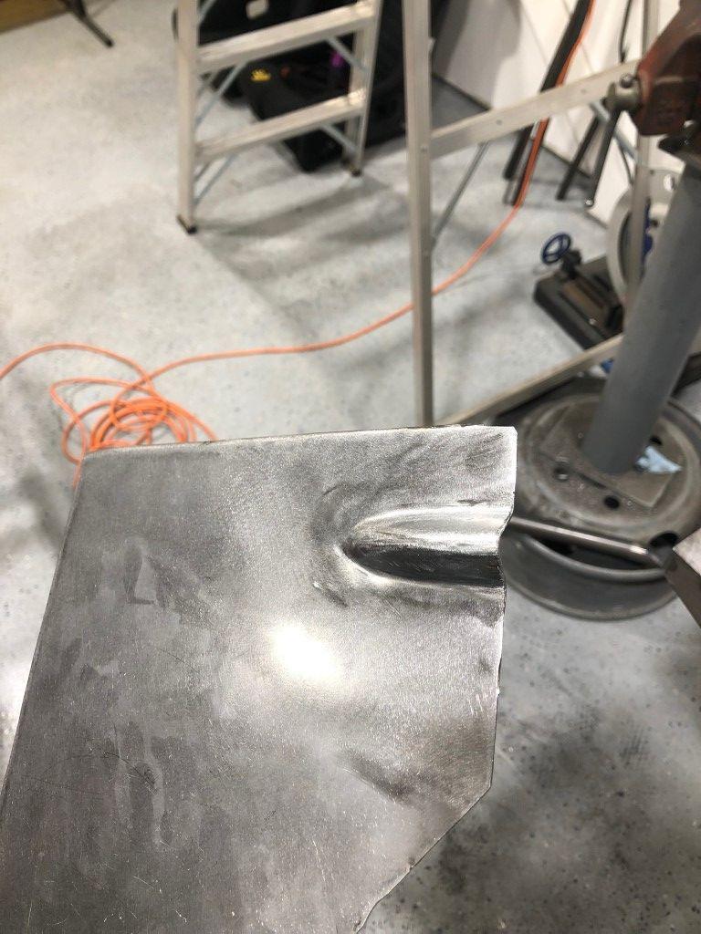
The fire wall has a nice horizontal bead that I cut through. I wanted to retain it instead of hammering it flat to make welding easier. I cut the bead out of the original piece and used it on my patch.
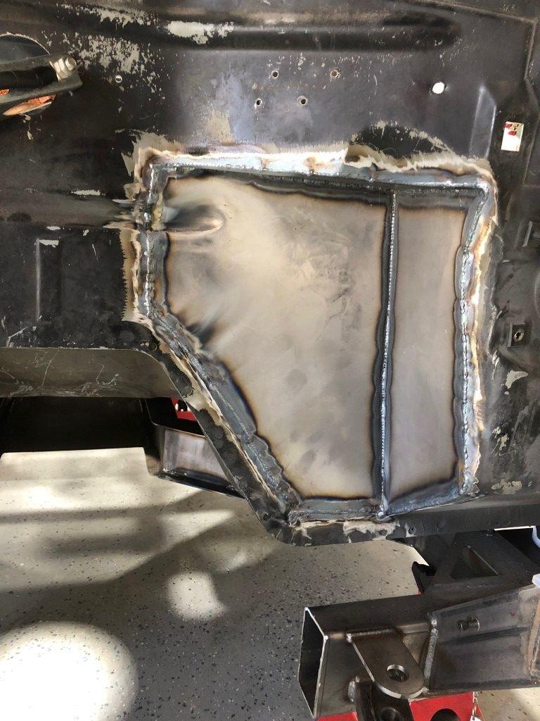
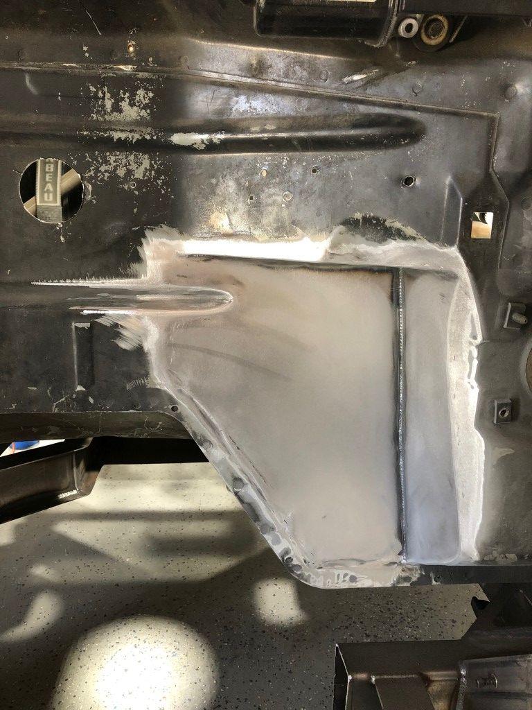
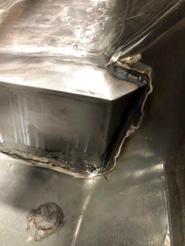
I don’t love sheet metal work, but I welcomed the challenge and it taught me quite a bit. I chose to tig weld this to make smoothing it out easier with the softer tig weld.
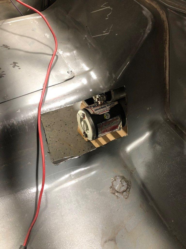
The bellhousing/starter combo (more used race parts) uses a reverse starter configuration. Slight clearance issue here. More cutting and patching.
To wrap up the front chassis fabrication, I added an X-brace. I did add another bar to connect the tubes coming through the firewall near the cowl, but I do not have pictures of that process.
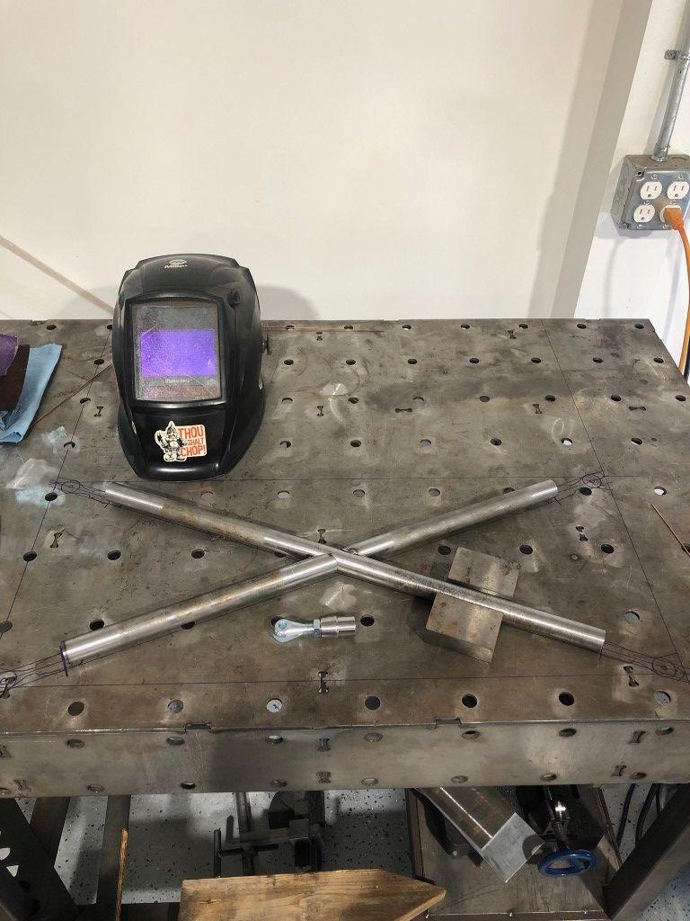
1” OD tube for this brace.
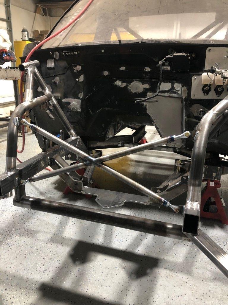
The brace mounts with slotted clevis ends onto ¼” tabs welded to the chassis.
The last part of this post will be the exhaust. I had always thought that running the exhaust down the rockers would be neat. It would also help keep the transmission fluid temps down on the road course. On vehicles with an undertray (which this has), airflow doesn’t carry off heat like an open bottom car, especially with traditional exhaust running near the transmission.
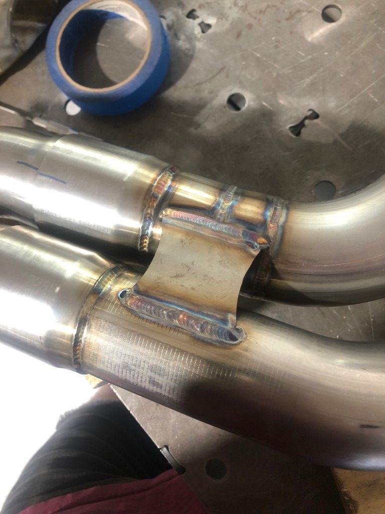
I had a tight space to fit the headers between the toe board and the chassis. I couldn’t fit a 3 inch collector in there which forced a tri-Y configuration. 1 ¾ inch primaries into 2 inch “secondaries” and then a 3 inch collector. The “secondaries” would fit between the toe board and chassis. This was one of my most challenging tasks to date.
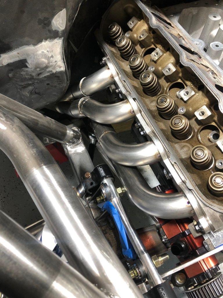
I learned a lesson in packaging on this truck. The engine in OBS trucks is offset about 2 inches to the passenger side. That combined with a dry sump oil pump and the associated lines gave me some headaches later on. In some areas, there is less ⅛ inches of clearance from one component to the next.
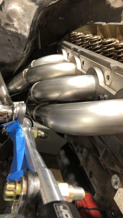
Single slips joints transitioned the primaries to the secondaries.
In order to install the headers, they needed a break point. I used two double-slip joints to attach the collector to the header. I tried to do everything the “right” way. I back purged everything and tried to shoot for zero gap on tube fitment. I welded the majority of these joints without filler material.
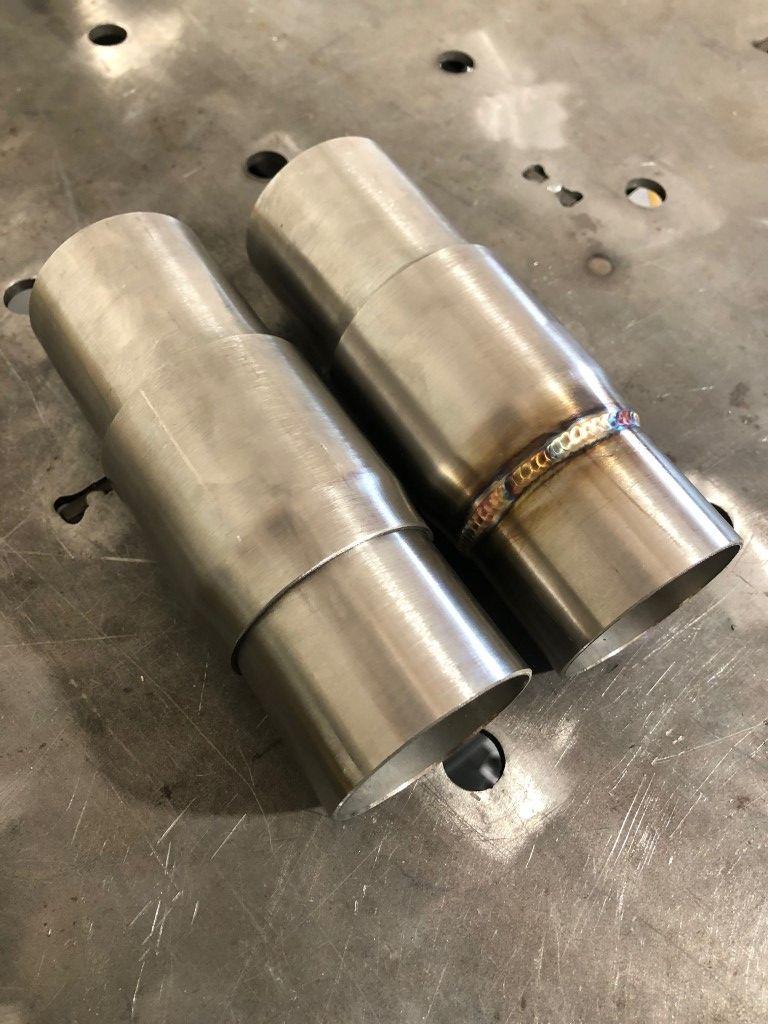
Close up of the double-slip joints.
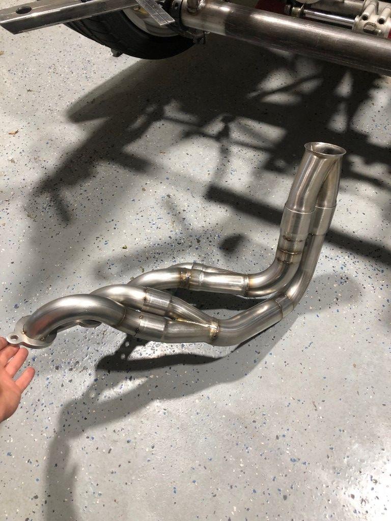
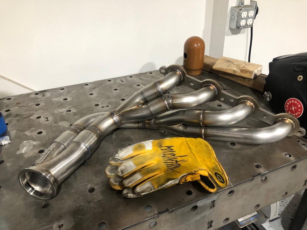
Driver Side
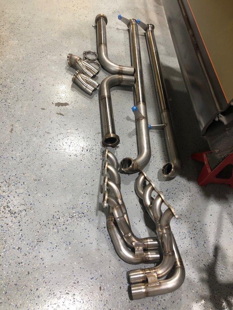
This is the complete kit.
Thank you for reading!
Jimmy
Instagram: jimmer_king
-
11-25-2024 #12
Registered User
- Join Date
- Jun 2019
- Location
- Nashville, TN
- Posts
- 24
PART FOUR: Oil System Setup, Transmission Setup, Final Fabrication, Paint
At this point in the build, things really started coming together. I could see how different parts worked together as designed. One major objective had to be tackled: finish a dry sump system that used second hand parts and without bracketry designed for an LS engine.
The dry sump system would not be compromised because it’s a necessity for race cars on slicks, however I didn’t have 5-7k to spend on a fully engineered setup from one of the major companies. I mounted my engine using a motor plate, and that complicated things further. That added a ¼” offset to the front drive, and I couldn’t find any off-the-shelf solutions to make the front drive work as a whole. I’m guessing this is because most people who run motor plates are drag racers, and those cars often run electric water pumps and no power steering.
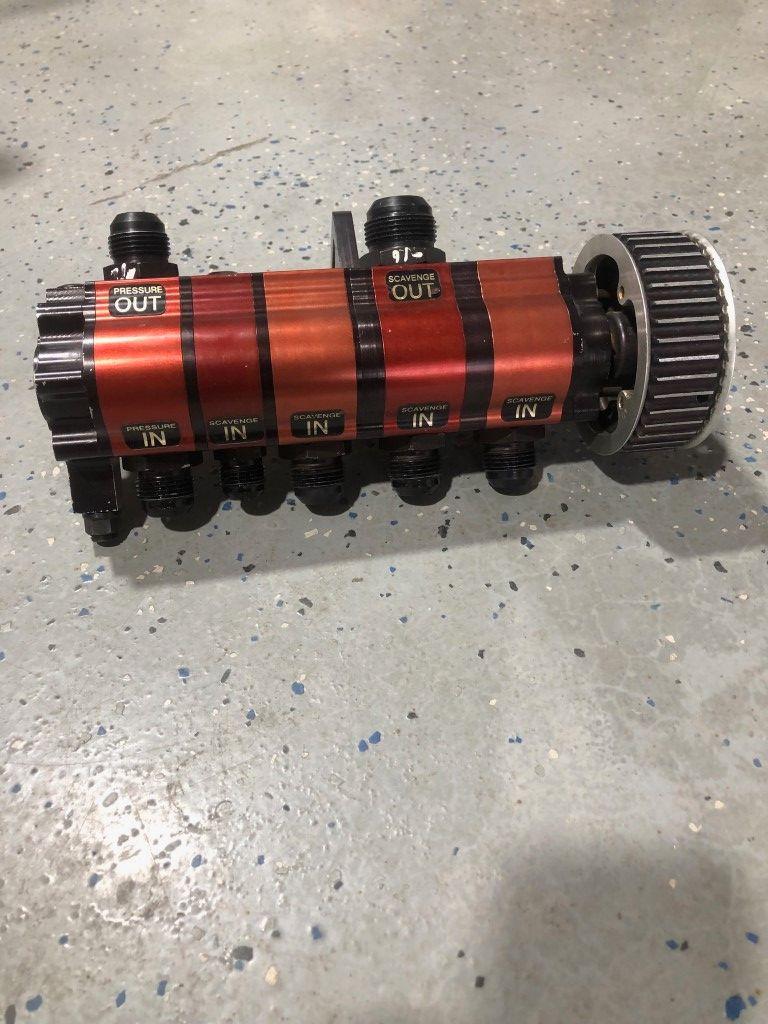
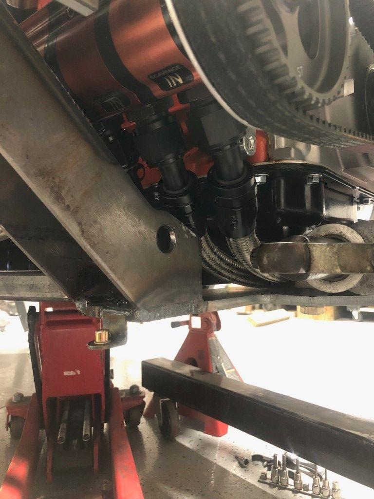
This is a Barnes 5 stage pump. 3 stages scavenge (12 AN) from the oil pan, 1 stage scavenges (10 AN) from the crankcase, and 1 stage (12 AN) pulls oil from the tank and pumps it into the engine. From left to right: pressure stage, crankcase scavenge stage, and then the three oil pan scavenge stages. The scavenge stages are internally bypassed which allows a single return line to the tank. That’s the bigger 16 AN fitting you see on top. This helps a lot for saving space as some oil pumps are not internally bypassed and you need an external manifold to run a single hose back to the tank.
I found this unit used for $500. They are around $1500 new. After buying this, I contacted Barnes to ask how I can verify it is in good working condition, and what speed I should run it at, etc. They contacted me and said if it spins freely and pressurizes the system, there’s no real cause for concern. Pump speed should be roughly 50% of engine speed and I could adjust the pressure using an adjustment screw on the back.

Here’s an example of a pump with a manifold. It is a little more complex and takes up more space.
To make the pump work, I used a “builder’s bracket” from ICT. It bolts to the side of the block. This gave me a few holes to fasten the motor plate, and I used two holes to mount the pump. I modified the pump bracket to fit against the block. Laterally, this is as close as the pump can sit to the block.

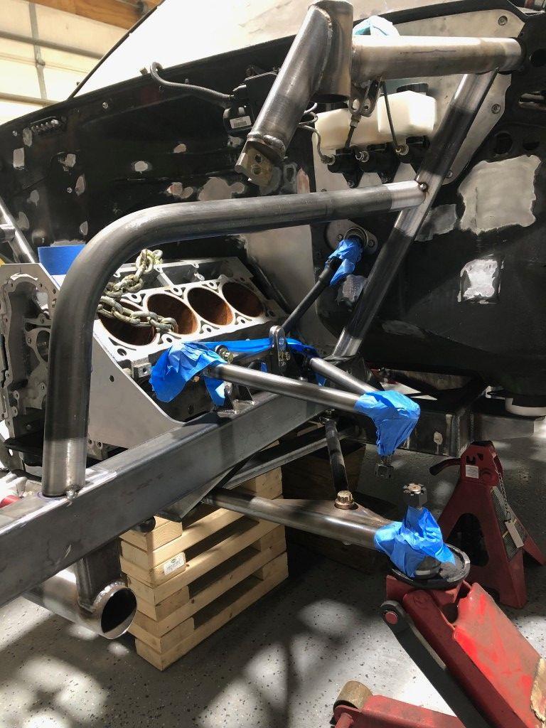
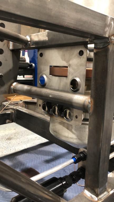
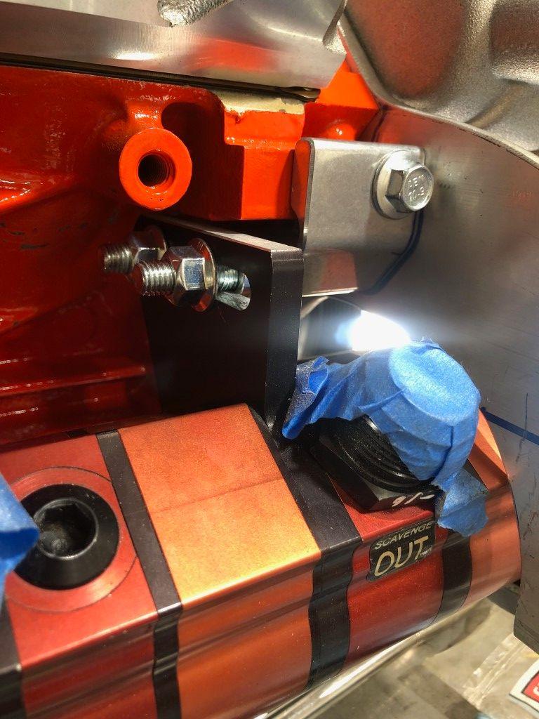
These are the three scavenge ports on the oil pan. Two hoses run around the front of the pan and one runs under the bell housing. The pressure feed hose is not shown, but resides next to the fitting on the right side in this photo.
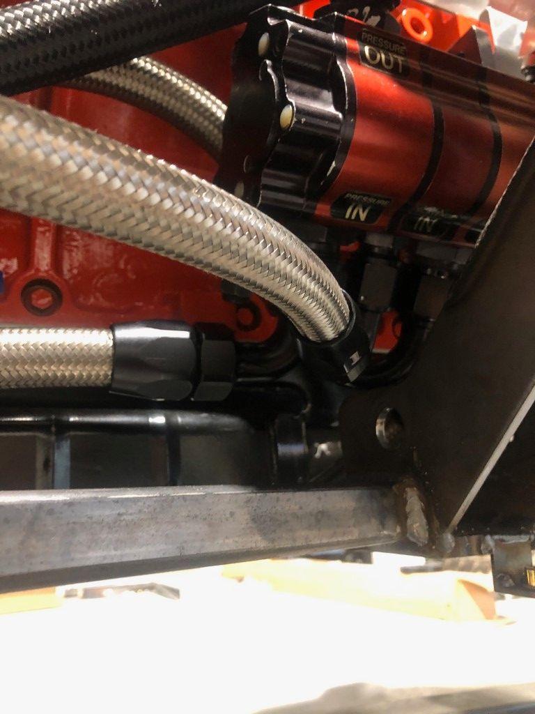
You can see some of the scavenge hoses here along with the pressure hose (left most fitting). It is a tight fit to the LCA mount. I would learn that these fittings have to be tightened with the engine out of the truck. Not much can be done once it is sitting in the chassis. I suppose that’s why you see really high end race cars use wiggins fittings. Wiggins fittings slide straight on and off, seal with o-rings, and use a clamp to secure it. I imagine they can be serviced even in spaces tighter than this. The downside is they are ridiculously expensive.
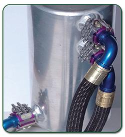
Wiggins fittings for reference. Most often made by Brown & Miller Racing Solutions.
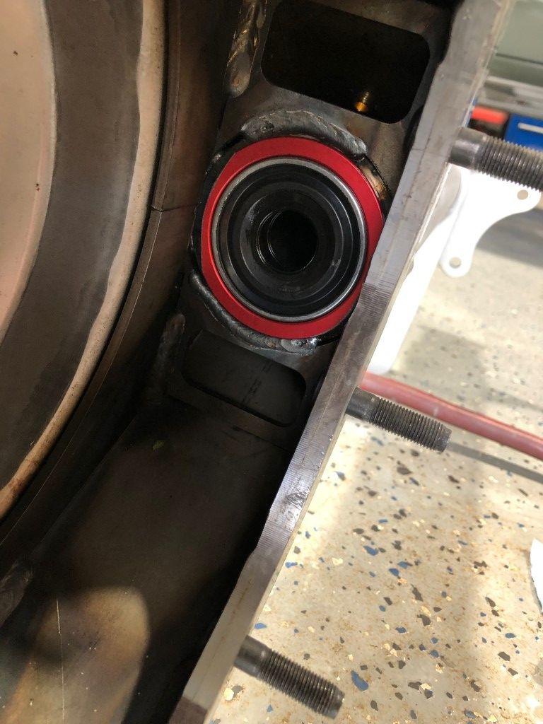
These are the remaining scavenge hoses. They fit very tight to the rack, and you can see where I had to cut the corner of the LCA mount to clear the fittings.
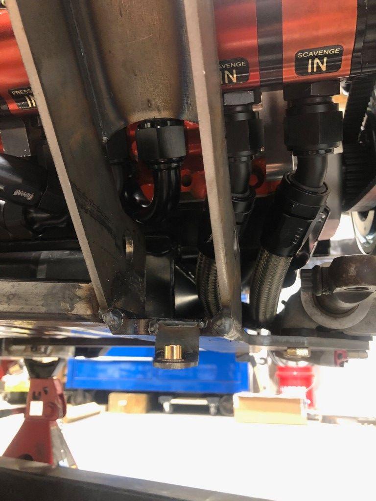
Another look to see the packaging of everything.
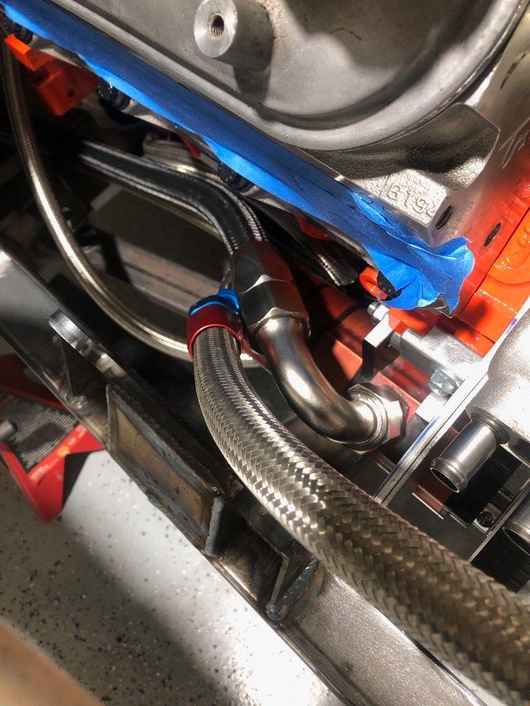
The silver fitting is the 16 AN hose that returns the oil to the tank. The blue/red fitting is the pressure hose.
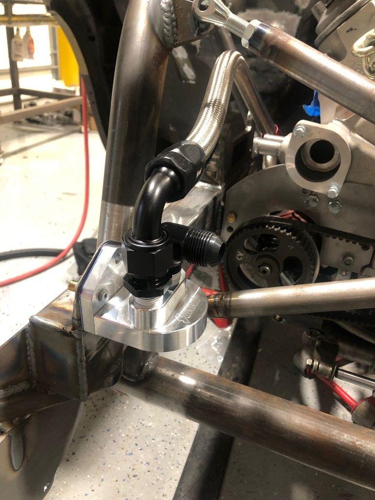
The other end of that hose attaches to this remote filter housing. After getting through the filter, oil runs to the driver side of the block, into a port to feed the engine.
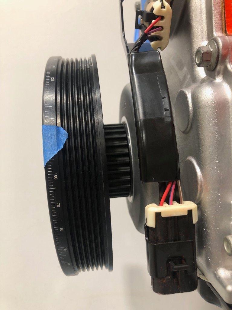
This is where things get weird. With the ¼” offset from the motor plate, I needed to space the crank pulley ¼”. I couldn’t find spacers for this application that were thick enough. I know ATI can make a custom length hub for any application, and that comes at a cost. I ended up getting a ¼” spacer laser cut to slip over the crank snout. What I didn’t realize is the hub of the pulley starts to taper off toward the end. With the pulley spaced out, the hub would not contact the seal in the timing cover.
Note the slight taper at the bottom.
So, how could I overcome this?
I flipped the seal around and installed it backwards. A seal installed backwards would have the lip extending forward from the engine rather than back toward the engine. This small change would allow the seal to make contact with the hub in the proper area. Practically, it makes more sense to run the seal this way on a dry sump engine. The engine no longer has positive crankcase pressure. The vacuum pulled on the engine will actually pull the seal lip harder against the hub.
In this diagram, the “primary lip” is what we’re concerned with. With the seal and shaft in the diagram, the crankcase would be to the right and the pulley to the left. By flipping the seal around, you can imagine how far to the left the “primary lip” is offset. This gained the distance needed to seal properly.
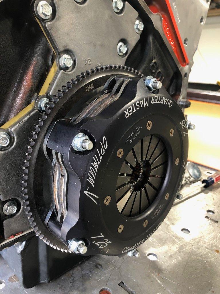
This is a Quarter Master Optimum-V 7.25” clutch. I bought this used clutch complete with flywheel for $300 online. Brand new it would be ~$1400. The only thing I changed is going from 3 metallic discs and instead opting for 2 “rally” discs. The “rally” friction material is ceramic/metallic. This makes for a much more forgiving driving experience than metallic friction material. The discs are also thicker. To reconfigure the clutch pack from 3 discs to 2 thicker discs, one floater plate is removed and the thicker discs make up for the lost stack height from the floater plate. The final stack is: flywheel, disc, floater, disc, pressure plate, clutch cover.
I’ve driven a metallic 3 disc clutch before (a different vehicle that weighs about the same) and they can be a real challenge to roll from a standing stop. I’ve done a small amount driving in this truck and it’s much easier with these discs.
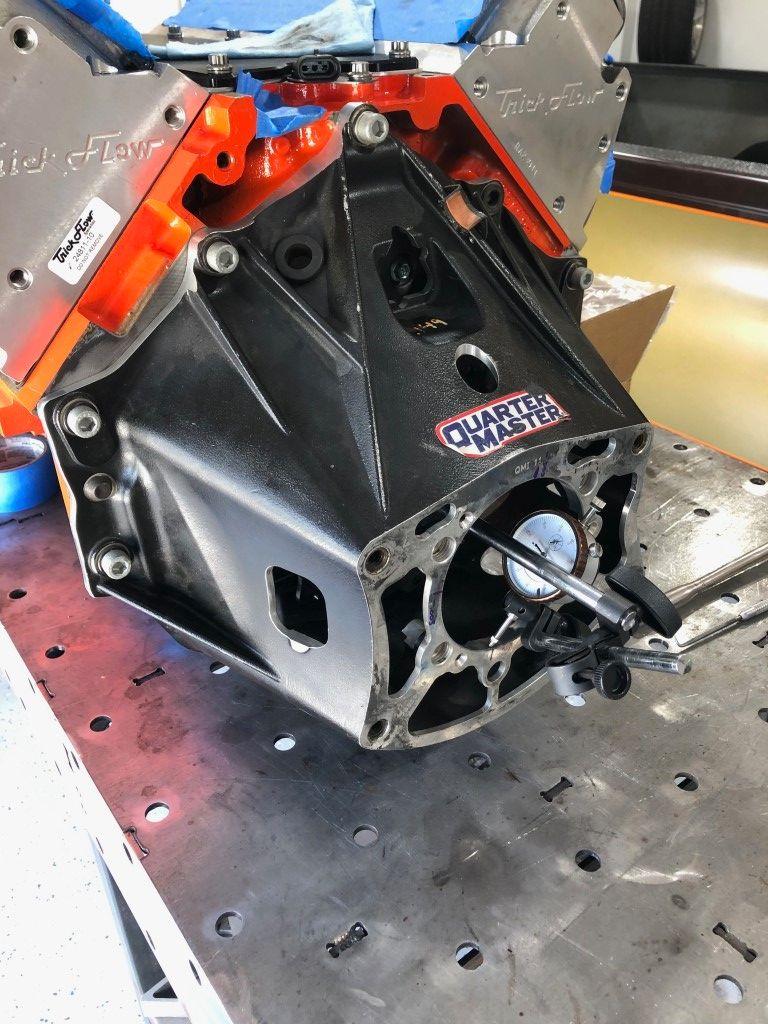
Always dial in the bell housing. I picked up this bellhousing with a starter for ~$250 online. This setup was used on the COT generation of NASCAR Cup cars.
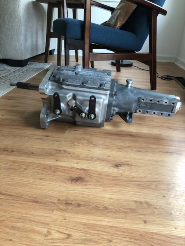
I bought a Jerico WC4 4 speed for $2800. I think you can see a trend in my desire for used race parts. The “WC4” designation stands for “Winston Cup”. 4 speed transmissions were used up until the current generation of Cup cars. In the early 2010’s, Cup car engines were making around 850-900HP. I think this will handle all the power I can muster out of my LS.
I was dead set on using a dog engagement transmission. For cars that see mostly track use, I don’t believe the common 6 speed synchro transmissions have a place as far as costs are concerned. To get a synchro transmission that is “road course ready”, they’re about double the cost of a used 4 speed dog box. You can upgrade 1st through 4th gears with dog engagement gear sets, and that’ll set you back another 5k. Not worth it in my opinion.
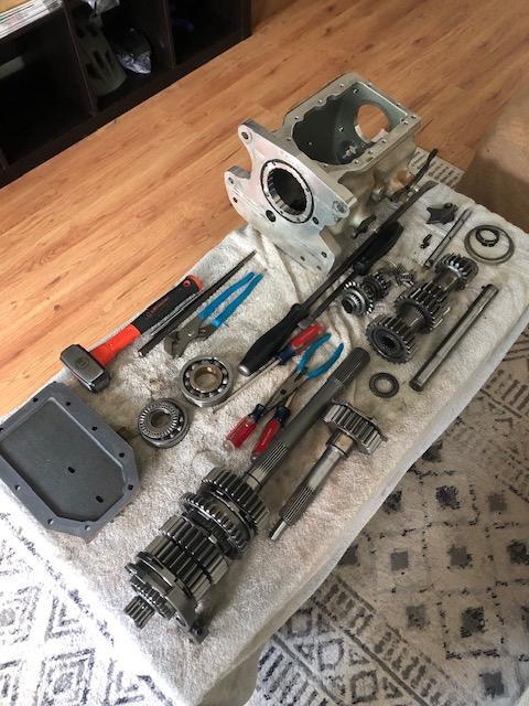
I changed 1st gear in this transmission. In total, I had about $3200 in the transmission.
Final gear ratios are: 2.12, 1.40, 1.18, 1.00.
Here are the last few fabrication items before the truck would be painted.
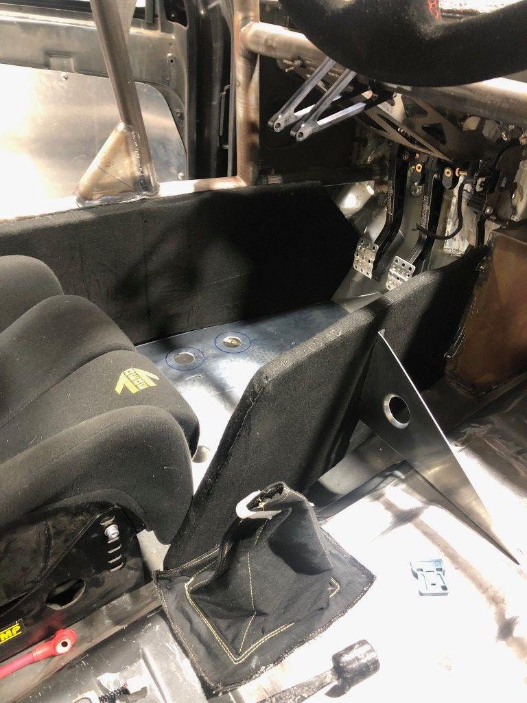
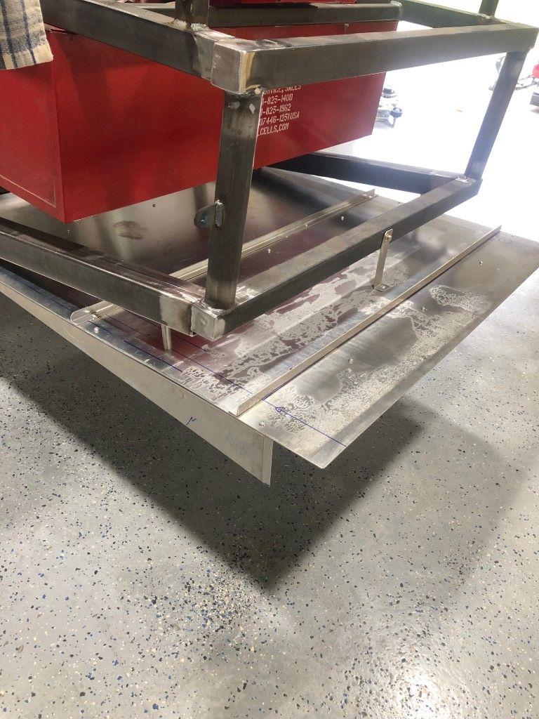
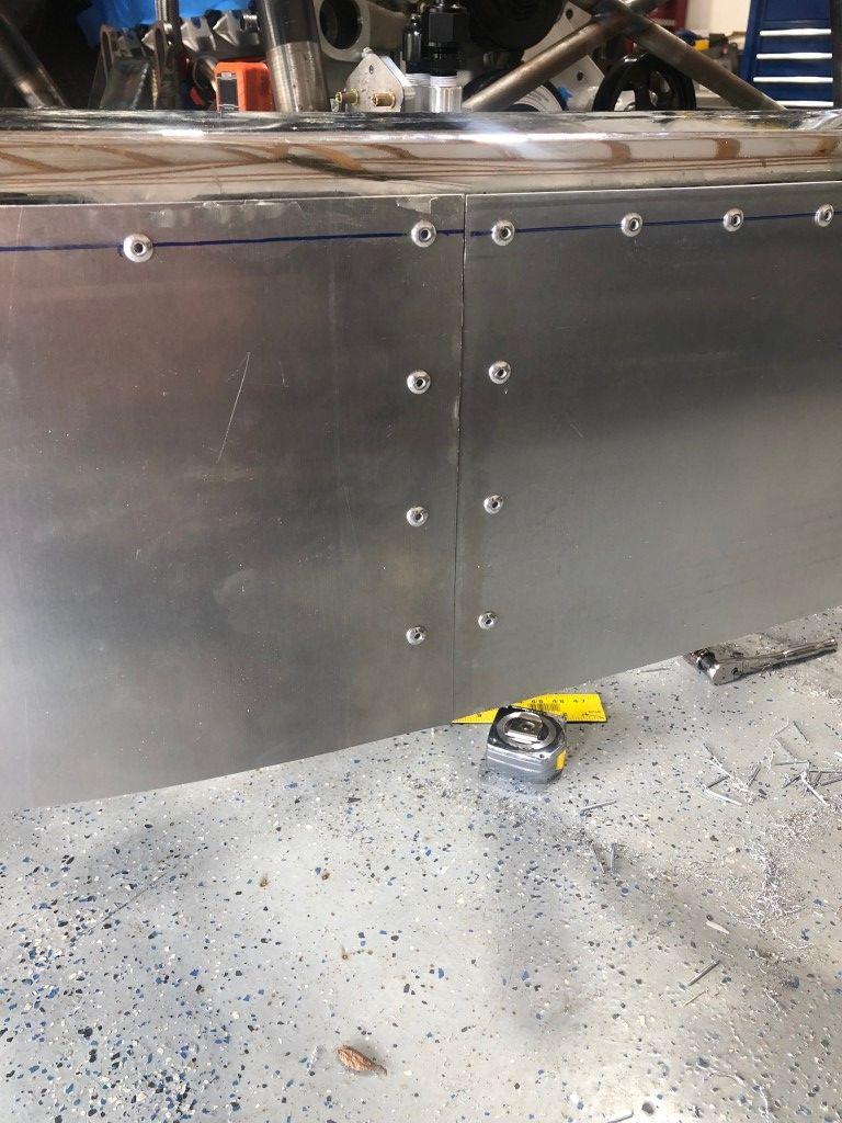
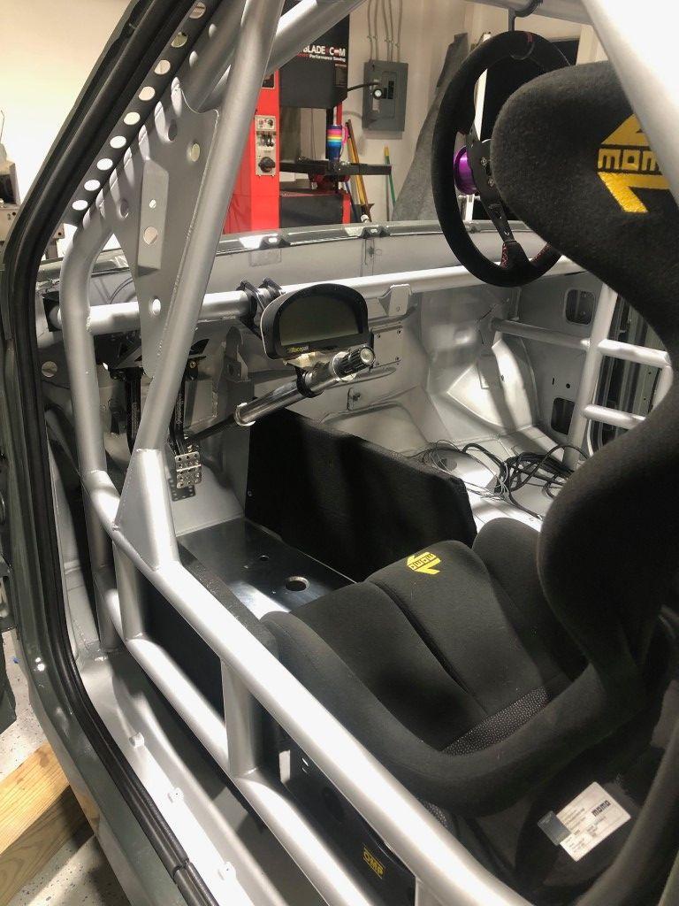
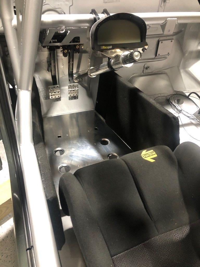
I built leg boards (not sure what they’re technically called) to give that cockpit feel. It’s another layer of safety for road course cars as well. I added a heel plate to give better ergonomic characteristics in the driving position.
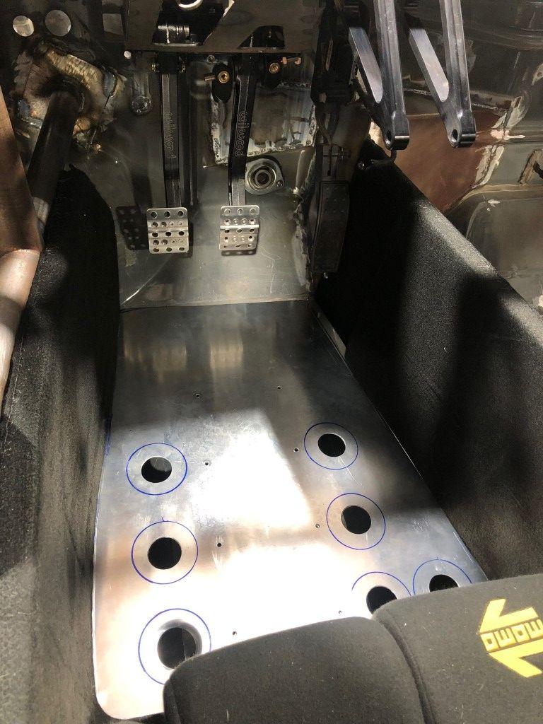
The heel plate is riveted to a bracket that bolts to the floor. The large holes eventually were flared using a dimple die. The leg boards are aluminum with foam pads adhered to the inside, and then wrapped in fire retardant fabric. They bolt to tabs on the rollcage and floor/firewall.
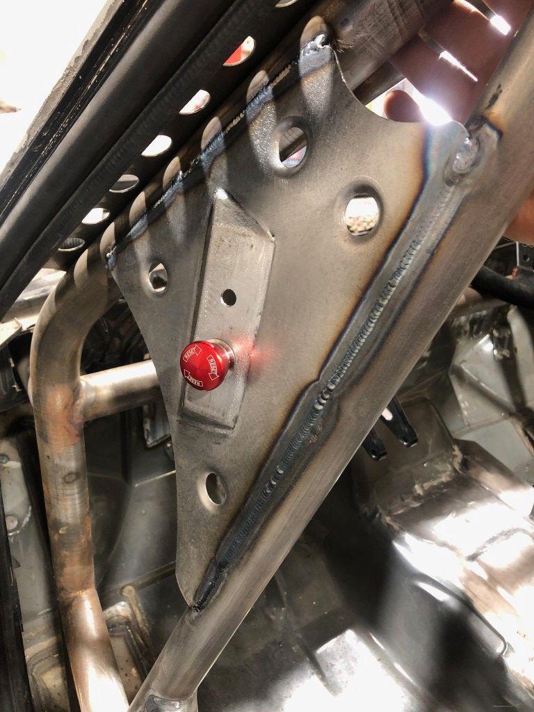
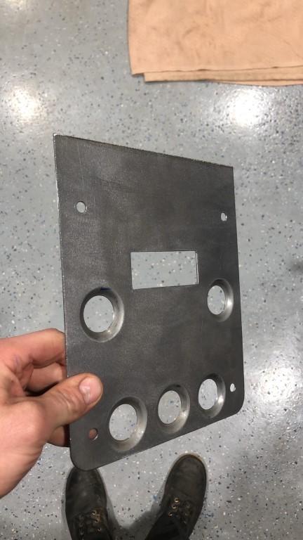
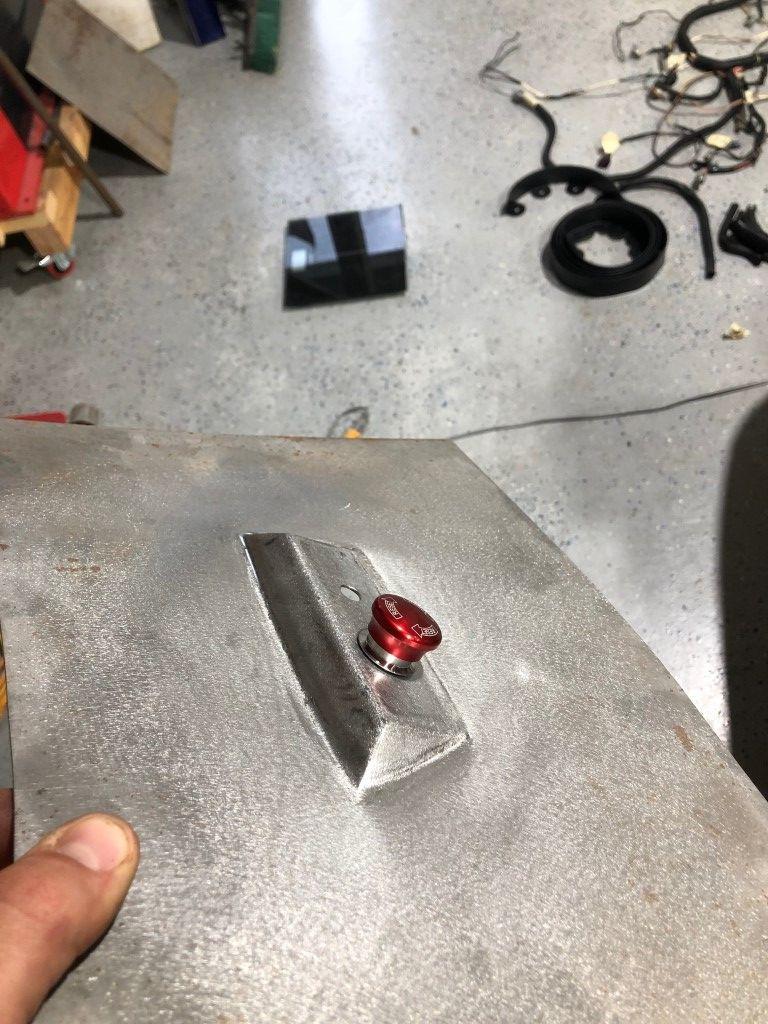
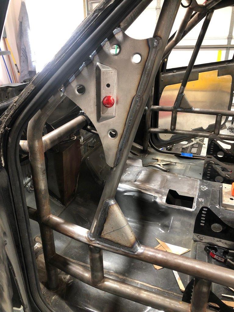
I made this plate to house the kill switch and fire suppression pull handle. Easily accessible to track workers in the event of an accident.
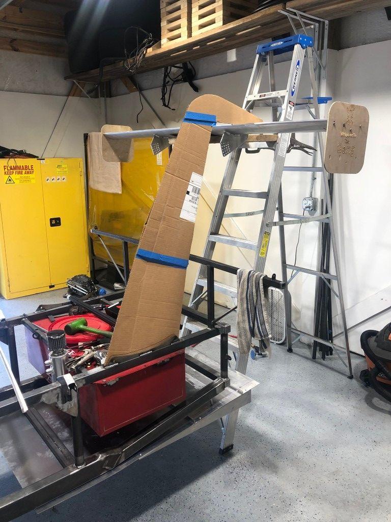
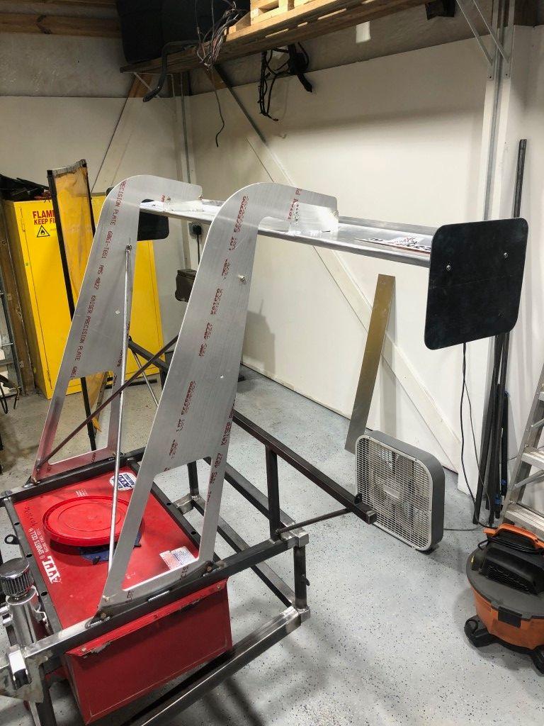
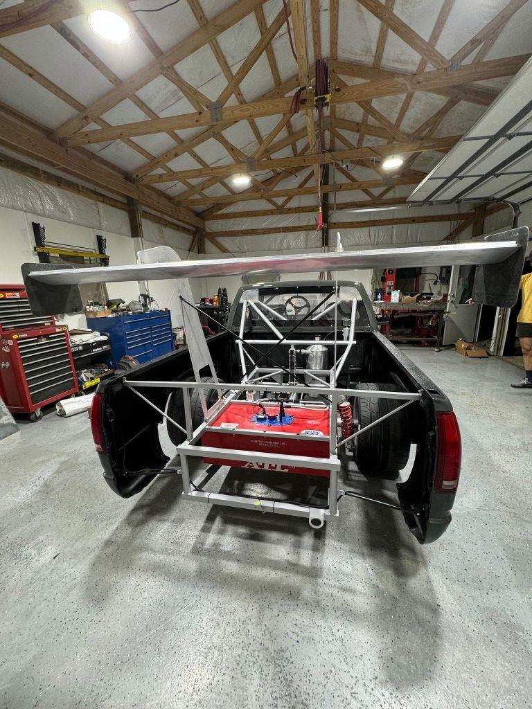
Now for some aero bits. I designed the pylons in the swan neck style. Swan neck mounted wings tend to perform better than bottom mounted wings. Leaving the bottom wing surface less obstructed will help achieve higher downforce.
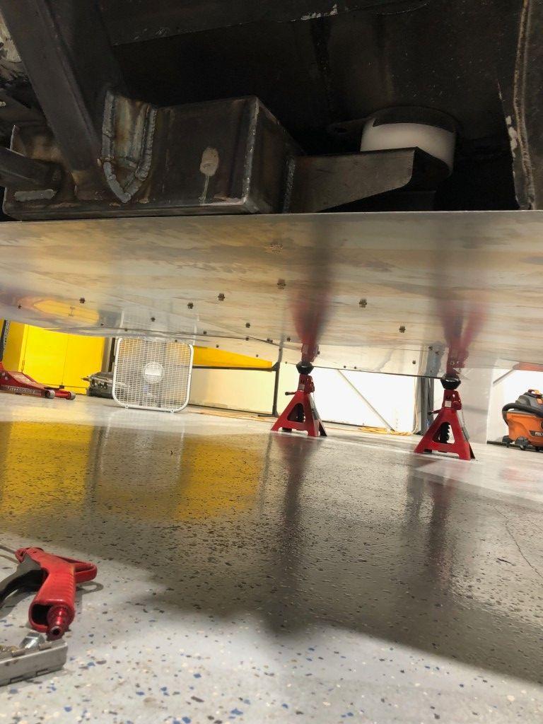
The undertray runs the full length of the truck, from the splitter to the diffuser. It attaches with screws into rivet nuts on the chassis. This is a big reason why I designed the chassis on a single plane.
I went conservative on the diffuser angle. It’s to tell what performance is gained without a wind tunnel, so conservative guesses tend to be better. Too steep of an angle would cause flow separation and much less performance.
I cut the bumper in half on the long axis and removed the lower half. I didn’t need it with this airdam and it would save weight. A lot of rivets hold it to the bumper.
I don’t have pictures of the final splitter, so it’ll wait until the next post.
From here there’s a big jump to painting the truck and chassis. I’ll give a basic overview of the paint process.
I bought Omni single stage paint in Launch Green. This is one of the colors you can get on a Rivian. I sprayed it though a Spectrum paint gun (Harbor Freight). I’ve read that it is a copy of a SATA paint gun.
I’ve painted a few cars so I kind of knew what I was doing. The chassis, interior, and all other components were painted with Silver POR 15. I used a combination of aerosol cans and the paint gun. This is by far my favorite coating for metal surfaces. It takes a little practice to lay out flat with the paint gun, but the end result is fantastic.
Next time, I’ll cover the final assembly of the truck.
Thank you for reading!
Jimmy
Instagram: jimmer_king
-
11-30-2024 #13
Registered User
- Join Date
- Jun 2019
- Location
- Nashville, TN
- Posts
- 24
PART FIVE: Final Assembly, Carbon Fiber Dash Build
Ive really enjoyed designing and building the truck so far, but like a lot of people, I enjoy driving as well. It took about 10 months to get the truck to this stage and I missed the racing season for 2024. I look at that in a positive way because Ill have the winter to make minor tweaks to certain aspects of the truck that I overlooked or didnt put much thought into.
I dont have a ton of photos of the assembly process itself, but Ill share what I have along with photos of the truck assembled.

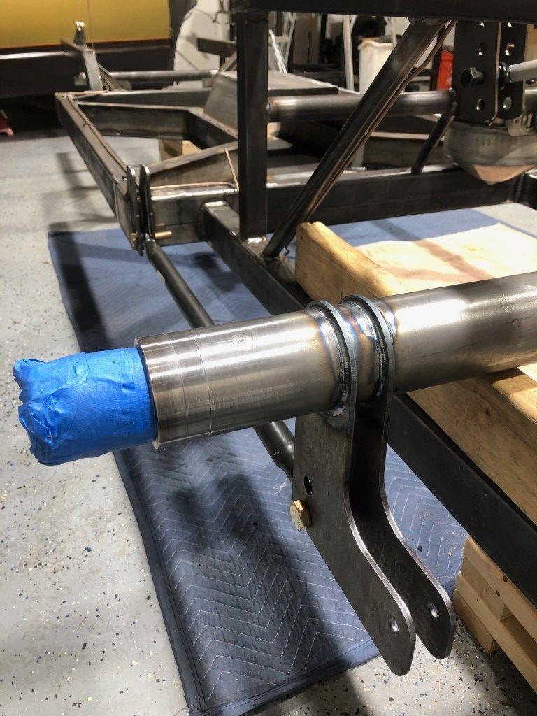
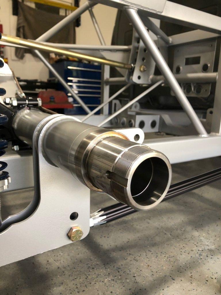
First up is the rear axle. I used these tube seals to help contain the oil to only the rear gear. Ive had leaking outer seals before and find them irritating. If I can try to avoid the issue completely, I will.
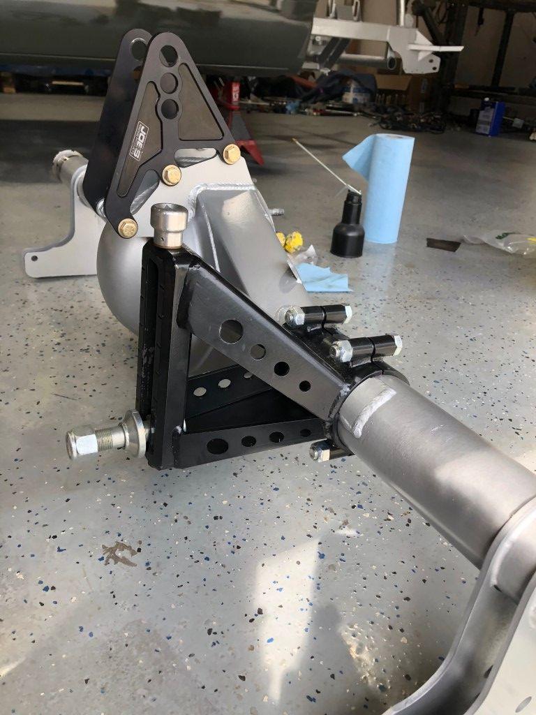
I installed the brackets on the axle before setting it in the chassis. The track bar bracket is adjustable with a ratchet. The silver looking knob on top has a ½ square drive to accept a ratchet extension. To adjust it, the track bar must be loosened with the ¾-16 nut, set to desired height, and the nut is tightened back down.
I always enjoy seeing crisp masking lines on fresh parts.
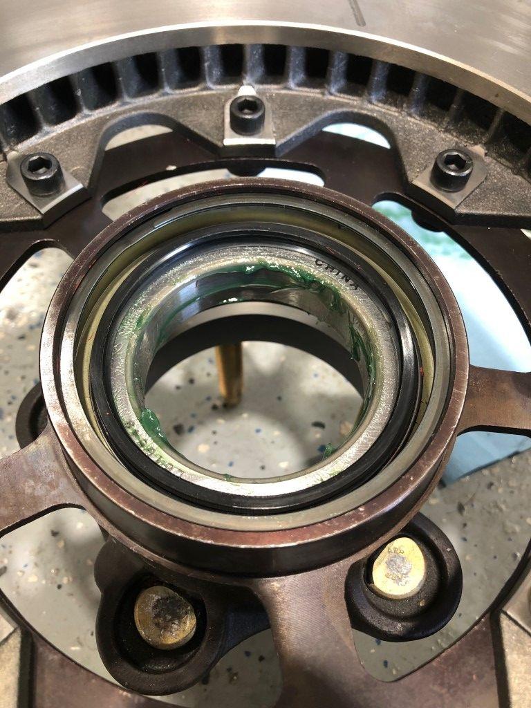
Bearing first, then a seal is driven into the back of this hub.
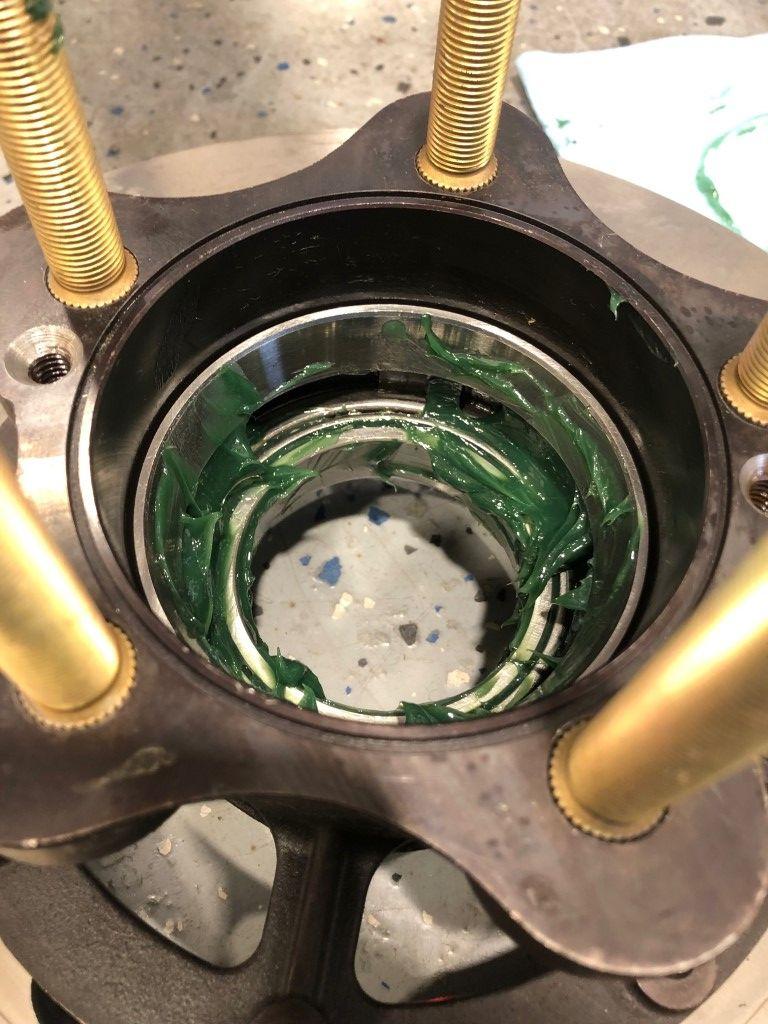
Without oil being sloshed to the bearings due to the tube seals, grease will lubricate the bearings.
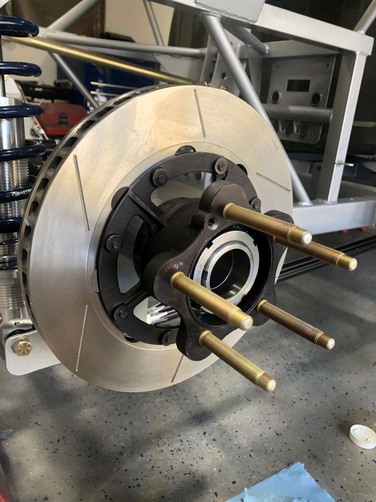
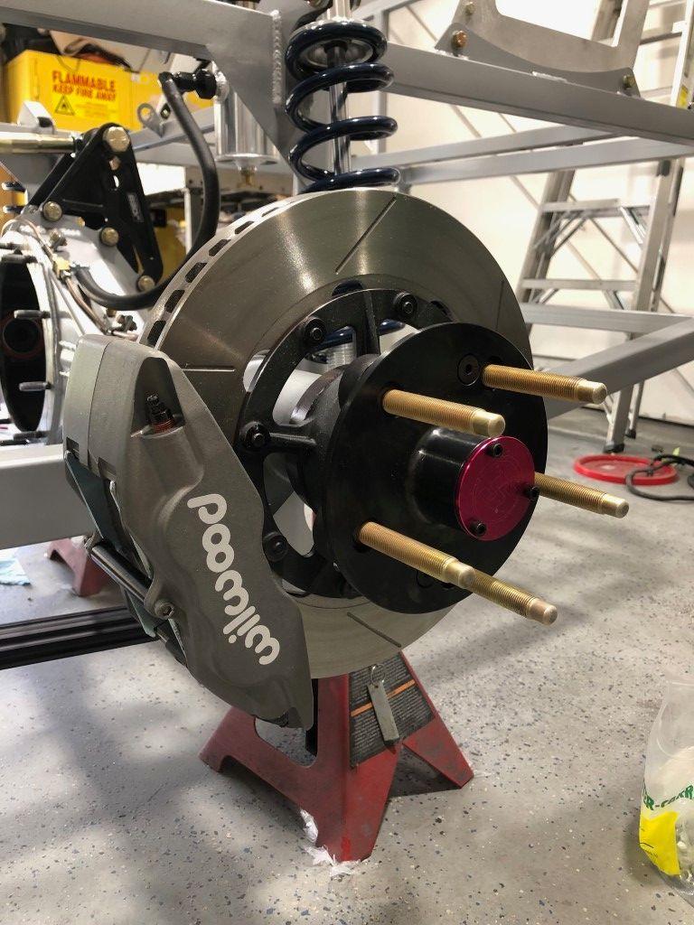
Axle, drive flange, and caliper installed. In the background, the bottom of the breather for the rear end can be seen.
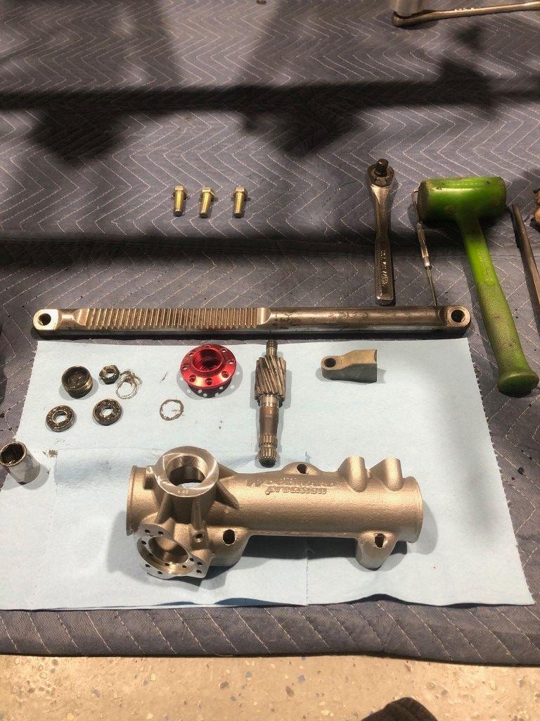
Up front, I bought a new housing for the steering rack assembly. The old one had a good amount of wear, and the housing comes with a rebuild kit for a reasonable cost. I took the rack internals to a local machine shop and had them mag checked. I believe this is fairly common practice among race teams between rebuilds. It is worth doing. I had four or five parts checked for $25.
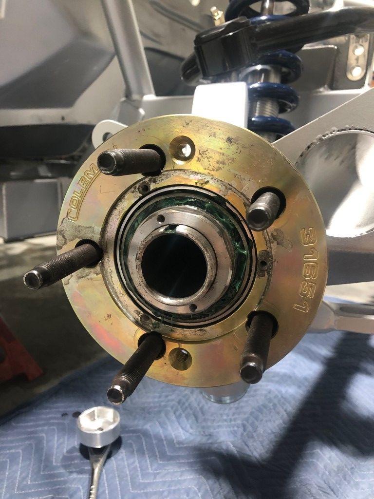
The front hub bearings get greased as well.
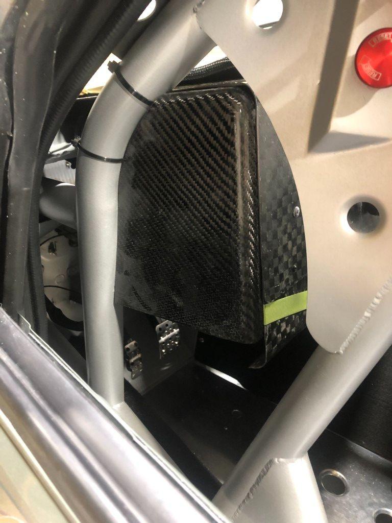
I built these cooling ducts previously. Im going to bail on these and move to an air deflector. Terry Fair at Vorshlag has done some testing to show how effective they can be versus a corrugated tube. It makes sense as the inside of those corrugated tubes dont flow well. For my truck, the tube takes such a poor route, making it tough to say how much cooling the brakes would have.
There are two fire suppression nozzles on the passenger side tube section, and one on the driver side. They point toward the fuel rails/oil lines.
Ill run a 4.86 gear for autocross. Thatll put my top speed around 112. The highest speed autocross I have ran in saw top speeds somewhere in the 80-90 MPH range. Ive had some comments about how much Ill have to shift with such a low rear gear. I don't foresee it being an issue. Below is a breakdown of speeds in each gear.
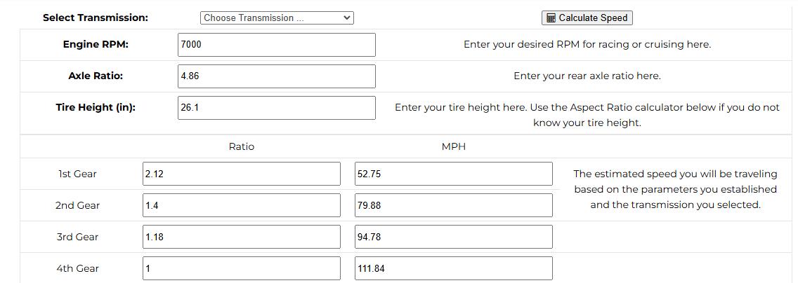
I think the low rear gear will be fine given the transmission ratios. With these dog engagement transmissions, theres no need to use the clutch when shifting up or down, so while shifting still takes time, it is likely faster than someone who has to heel-toe on the downshift. It will keep my left foot free to manipulate the brakes as well. I like driving with two feet (left foot braking) much more than having to use my right foot for both throttle and brake.
I have another rear gear that would be suitable for the road course. The ratio is 3.64. The speed breakdown is below.
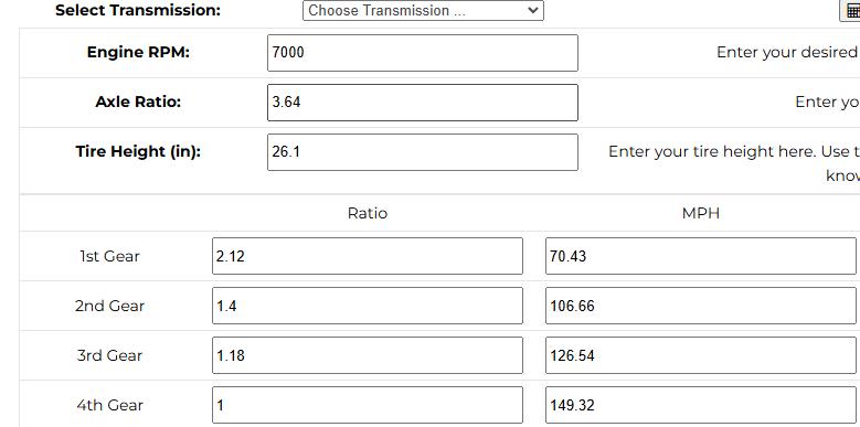
This should handle most road courses Ill go to. Ill probably pick up another gear (around 3.00) for really high speed tracks. With a 3.00 gear, top speed will be around 180 MPH. None of these numbers account for drag.

At this point the truck was technically finished. However, as I was wiring up the dash and some other things, I just was not in love with the interior. I needed something to make it more racecar-esque. I got a wild hair up my nose and decided to build a carbon fiber dash and replace the display I had at the time.
Ive done a decent amount of composites work before, although Ive always done it without the professional equipment. No autoclaves, no vacuum infusion, etc. The cost of composites is incredibly high when done with the proper equipment. Of course, the highest quality is achieved that way.
My method is a wet lay up with a vacuum storage bag providing tension on the mold. This is lower cost, yet retains decent quality. I will explain below.
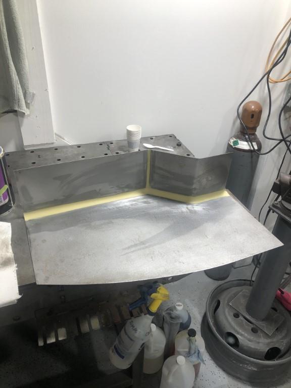
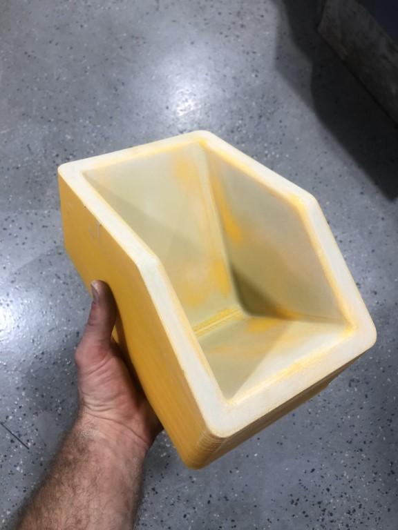
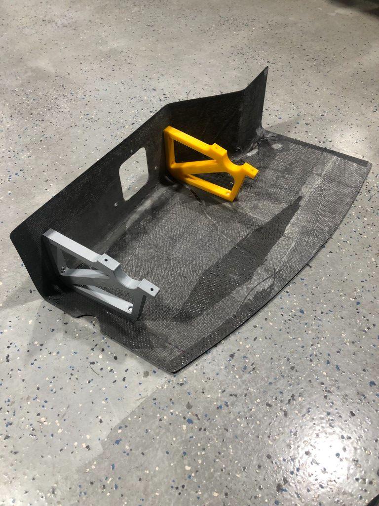
The dash is upside down in this photo. I used sheetmetal to create the mold. I would lay carbon on the inside (the side seen in the photo). I used body filler to create the radii for a smooth transition.
The next step is using a high build primer to smooth everything out. Its necessary to use 2K products here. Epoxy will react with 1K paint/primer. After wet sanding, I used polish to smooth the surface more. Then, I used 5 coats of wax and 3 coats of PVA release agent.
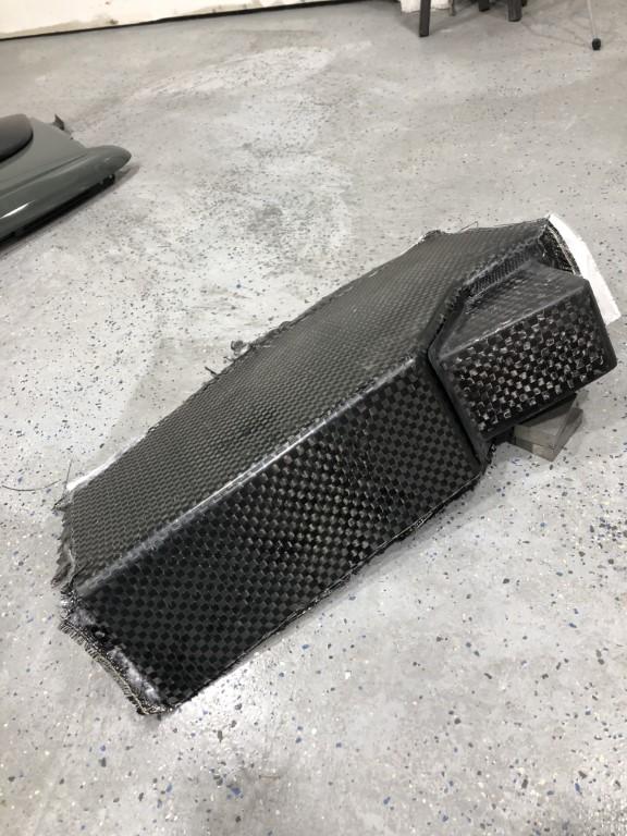
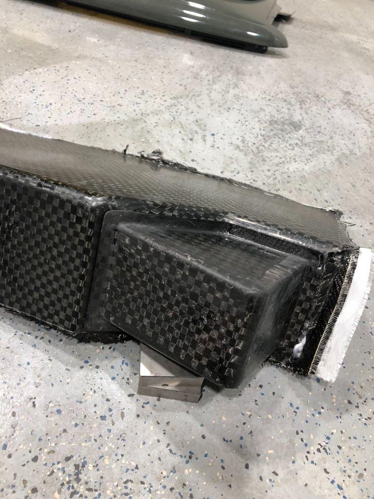
From here I laid carbon fabric with epoxy into this mold, and put the mold into a vacuum storage bag to cure. I have pictures of another part I made using the same process for reference.
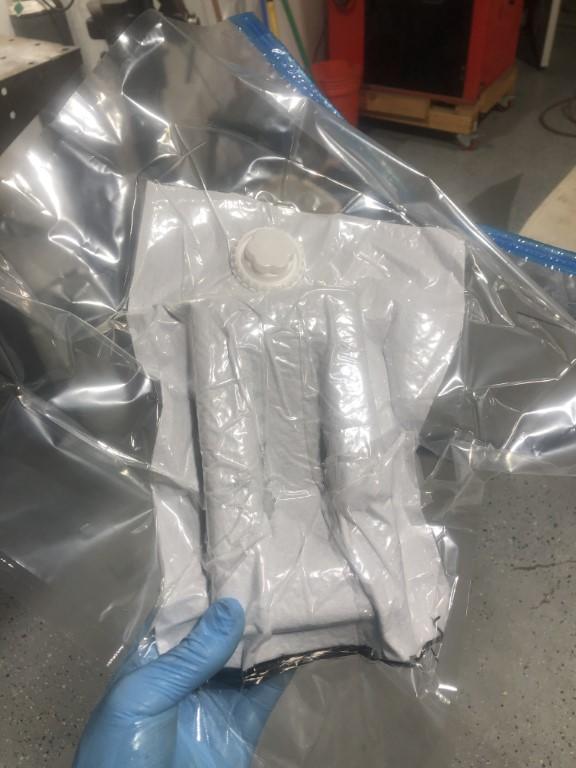
This is an unrelated part made using the same process. I just want to illustrate how the vacuum bagging process works. A breather cloth is used so that air can escape through the port. The vacuum ensures the fabric stays in the tight corners of the mold. The cure takes about 6 hours under normal conditions (70F temperature).
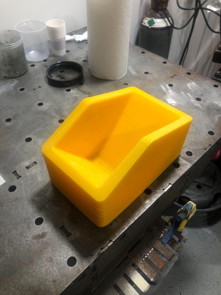
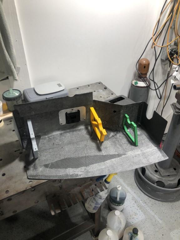
I also 3D printed molds. The same process applies. Sand, filler, 2K primer, wet sand, polish, wax, PVA. These can be delicate, so I try to wax and PVA as much as I can to get a clean release.
3D printed parts have a poor surface finish by nature. I tried to sand the layer lines as much as was reasonable and then skim coated the mold with filler.
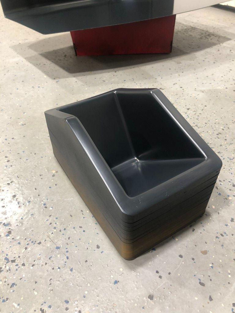
This is post polish, wax, and PVA. The more slick the surface, the easier the release. It is better to spend more time here than to have headaches when trying to get the part out.
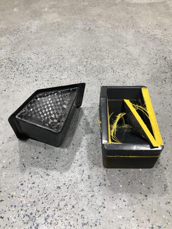
I was able to get two parts from this mold. I broke it on the second release. The part had depth to it which made it more difficult to release.
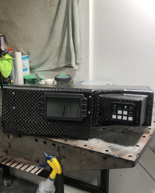
Here is the dash yet to be trimmed and associated pod.
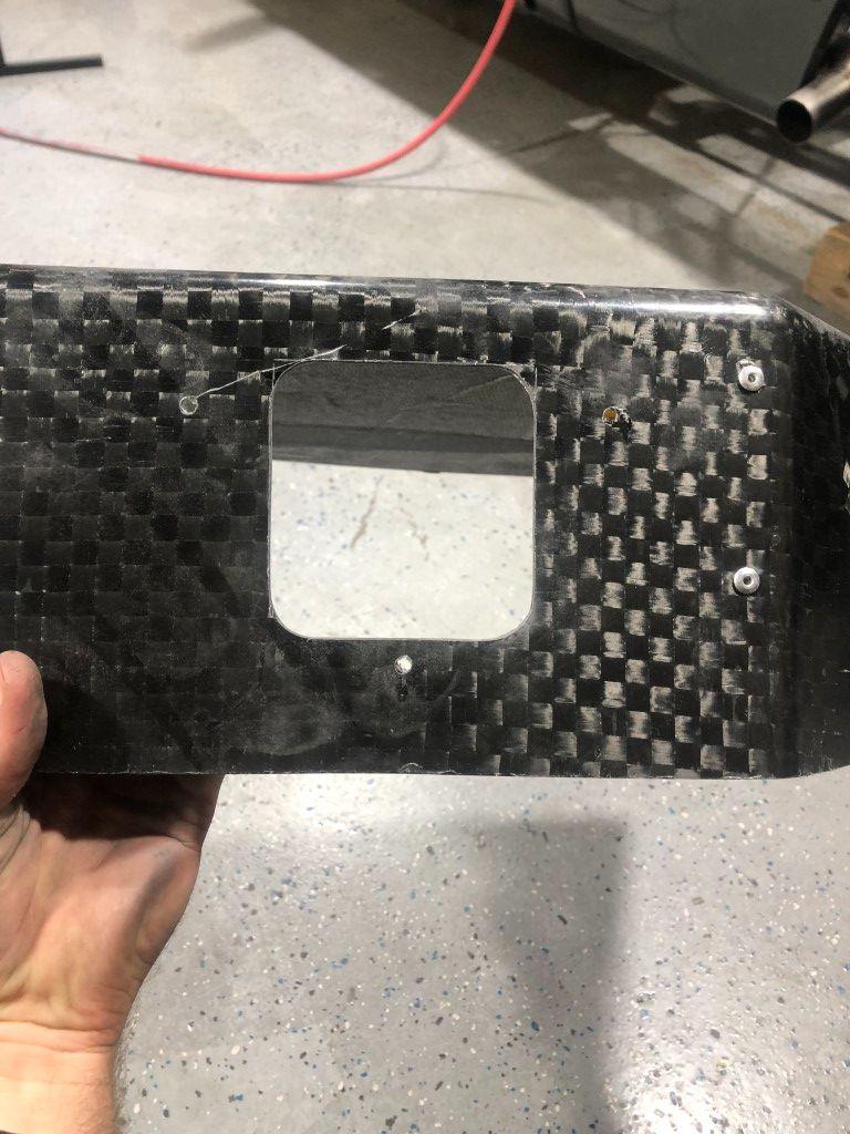
After trimming, I cut holes to mount the new display. A dremel helped here as carbon is easy to cut. Pneumatic tools are too aggressive and can ruin a part if you have a slip up.

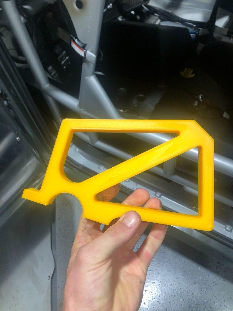
To mount the dash, I 3D printed these brackets that have a tube clamp feature to hold on the cross bar of the roll cage.
The bottom piece of the clamp feature is not shown in this photo.
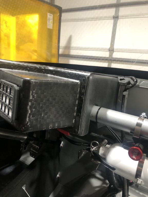
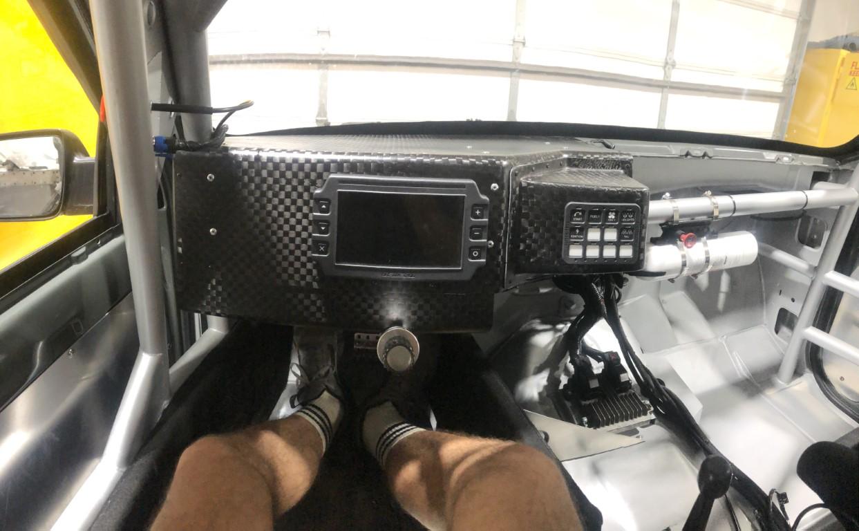
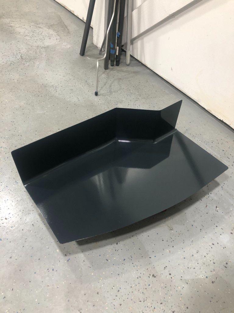
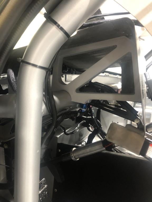
Final installation. The carbon pieces were all sanded through 600 grit and then clear coated in a matte finish. You cant see in the pictures, but there are small voids throughout all the pieces. Its hard to see them even from 3 feet away. This is what I would expect from this layup process. B grade results are great for a DIYer without the proper equipment. Even so, one could spot fill with epoxy, sand for hours, and make this look like a properly vacuum infused part. Personally, I cant justify that kind of time input.
I hope to post some more when racing season comes in 2025. I have some more upgrades/things to change planned over the winter, and maybe Ill post some of those.
Thank you all for reading!
Jimmy
Instagram: jimmer_king
-
11-30-2024 #14
 Registered User
- Join Date
- Jan 2002
- Location
- Crockett, Texas
- Posts
- 568
Fantastic work!
 Don 67 Camaro RS/SS Texas
-
11-30-2024 #15
Registered User
- Join Date
- Nov 2018
- Posts
- 944
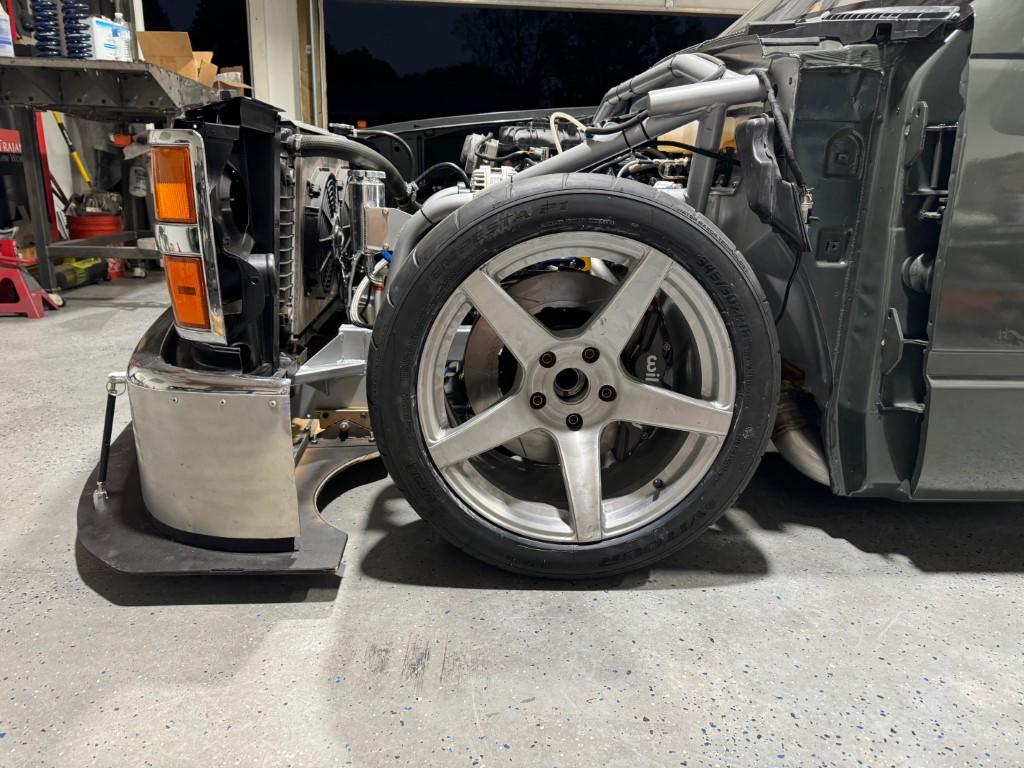
Nice work. That's an unusual brake setup, what is it from? I'm used to seeing rotors on lug nuts, not attached to the back of the wheel hub several inches behind the wheel.
-
12-02-2024 #16
Registered User
- Join Date
- Jun 2019
- Location
- Nashville, TN
- Posts
- 24
This is fully floating rear axle and they run a hub separate from the axle. Then the rotor mounts to the hub. Most axles are "flange" axles, and the wheel mounting surface is integrated to the axle itself. Originally Posted by Vimes
Instagram: jimmer_king
-
12-02-2024 #17
 Registered User
- Join Date
- Sep 2010
- Location
- Beach Park IL
- Posts
- 3,029
People tend to not see the total package, they just hear 4.86 and think your nuts. I do think the bigger issue you will have is the split between 1st and 2nd gear is big. Since the engine spins to 7k I bet there isn't a bunch of power at 3500 which is where you will find yourself in 2nd gear for a lot of lower speed turn arounds. If you could get a 1.55 2nd gear, you would probably only need to make a 1-2 shift after launch and never shift again for most autocross courses.I’ll run a 4.86 gear for autocross. That’ll put my top speed around 112. The highest speed autocross I have ran in saw top speeds somewhere in the 80-90 MPH range. I’ve had some comments about how much I’ll have to shift with such a low rear gear. I don't foresee it being an issue. Below is a breakdown of speeds in each gear.
That aside, nice fab work!Donny
Support your local hot rod shop!
-
12-02-2024 #18
Registered User
- Join Date
- Jun 2019
- Location
- Nashville, TN
- Posts
- 24
Originally Posted by dontlifttoshift
Thank you!
There's a chance I'll change gearing around, but downshifting is more accessible on the autocross course with a dog box (for me anyway). I feel I can still threshold brake and downshift compared to my heel-toe shifting where I don't think I'm as quick or hard on the brakes.Instagram: jimmer_king
12-12-2024 #19
Registered User
- Join Date
- Jun 2019
- Location
- Nashville, TN
- Posts
- 24
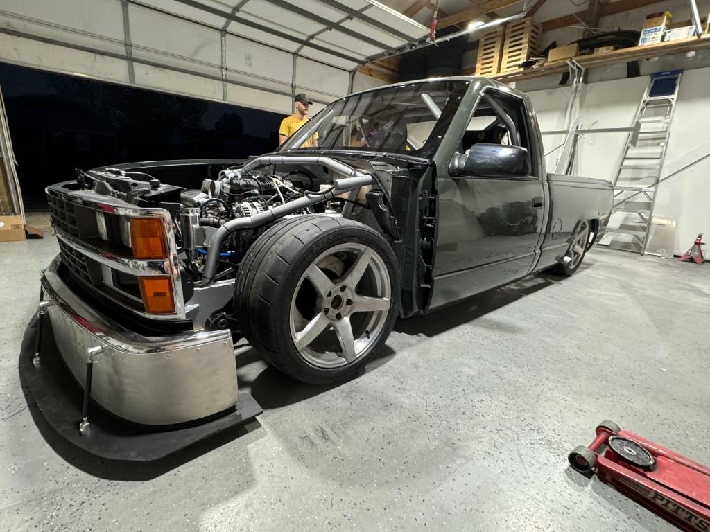
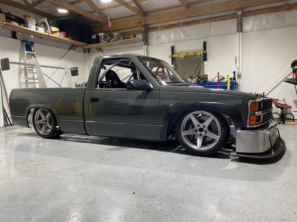
I have some "official" photos to share with everyone.
Instagram: jimmer_king
12-12-2024 #20 Registered User
- Join Date
- Mar 2022
- Location
- Florida
- Posts
- 224
amazing fab work. Great job. What does it weigh?

 Reply With Quote


