


Results 21 to 40 of 48
-
07-16-2017 #21
 Registered User
- Join Date
- Aug 2008
- Posts
- 43
So the next step is to install the center bracing that goes inside the mount. I sprayed some weld through primer in here and the inside of the brace.
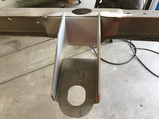
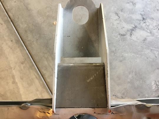
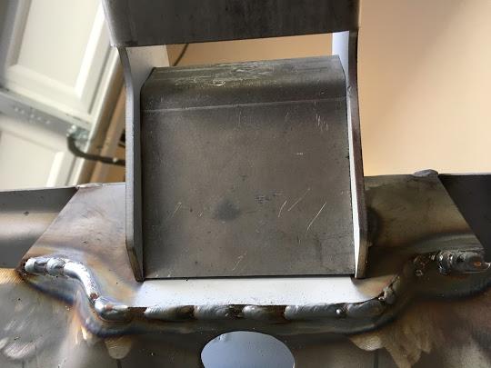
After these were tacked in place, the instructions tell you to pretension the frame 3/8-1/2 inch as the frame tends to bow out when adding this kit. So I had to use two rachet straps to get to the 1/2" mark. Then I welded some 2"x 2" tubing to the top of the frame after it was pretensioned to hold it in place. After this the straps were removed.
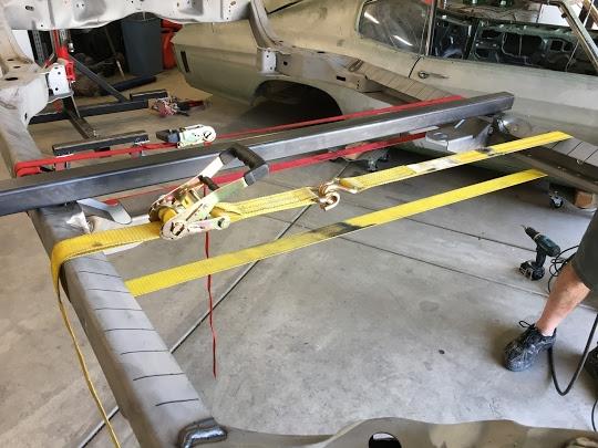
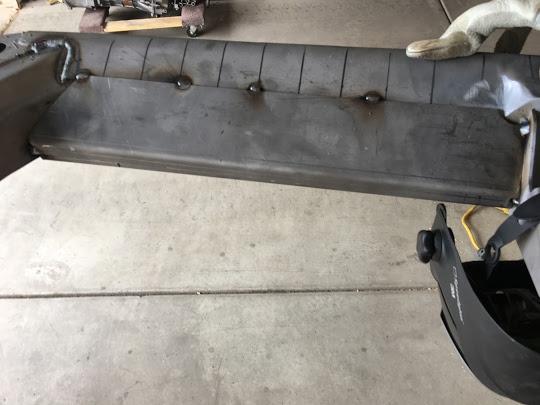
Next step is to start installing the lower plates. I started by priming both the inside of the plates, and the whole inside of the frame. Then I tacked it along the bottom side of the original frame and where the new plates attach. NOTE:. The plate does not sit flush with the frame. The stock frame is not level with the ground, and the inside edge has a slight downward slope. I made sure the bottom edge of the frame was perfectly aligned with the plate using C-Clamps and Body Vice Grips.
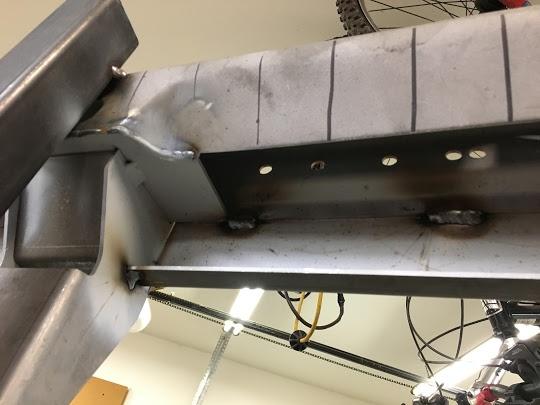
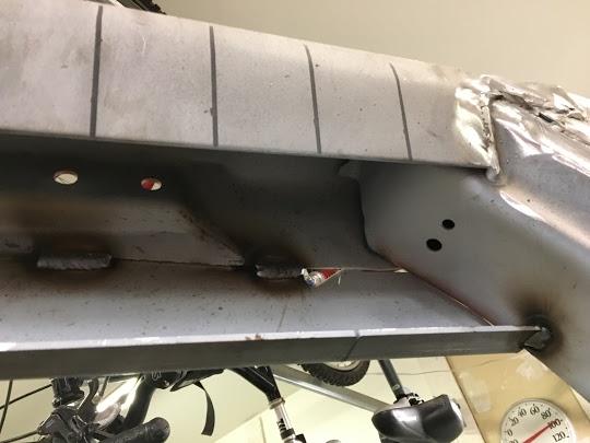
Then repeat on the other side.
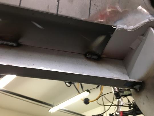
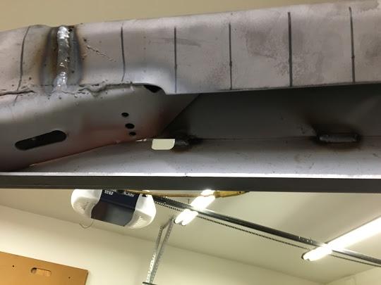
Then you do the same thing to the front plates. I had to trim about an inch off of each one of the front plates on my frame. The rear plates were not trimmed during my install... It started to get hot at about 1:30, so we cleaned up and put everything away for today. With the frame on the rotisserie, it makes fitting the damn thing in my garage a bit of a challenge...
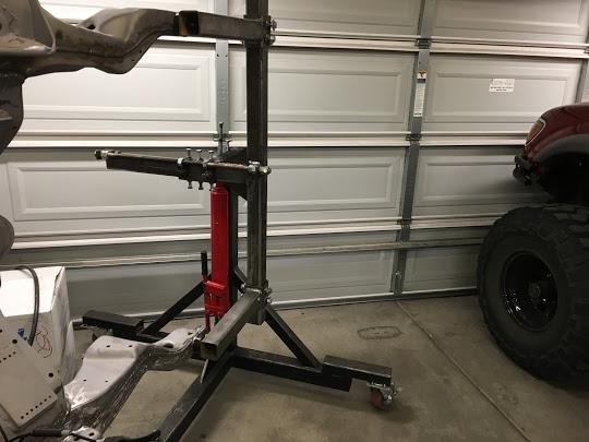
To be continued tomorrow.
-
07-17-2017 #22
Registered User
- Join Date
- Aug 2008
- Posts
- 43
Alright kids. Now it gets fun!!! Today the high in Phoenix was 97 degrees, but it was 50% humidity, so it was pretty hot and soupy again today.... Today was a big day, and I got a TON done on the bracing kit. I also decided yesterday that I basically wanted to go over all of those factory welds and remove all of the dingleberries that have been there for almost 50 years. I'm not going for Show car quality, but I want it to look like someone gave a crap...
Started off at about 9AM this morning, and it was a nice 85 degrees. Started by clamping on the upper brace on the passenger side, then moved to the drivers side.
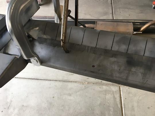
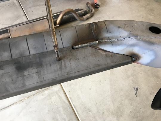
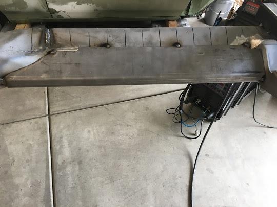
Then the fronts...
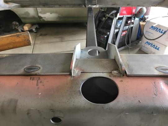
So yesterday I made a mistake when I installed the brace that goes inside the body mount. In the picture below, you can see that it does not sit level like the front and rear plates... lucky for me, I actually followed the directions and only tacked this piece on.
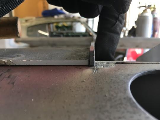
And here it is fixed...
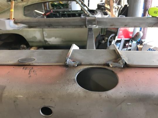
Repeat on the other side...
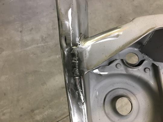
So While going over the frame, I found this little gem... This is the crossmember where the rear upper control mounts attach. Where this meets the frame the original weld was cracked, and this crossmember was lifting away from the frame...
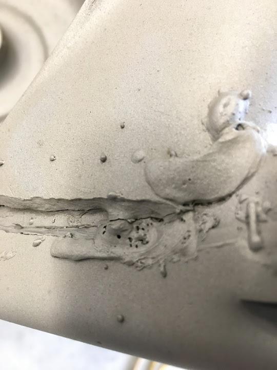
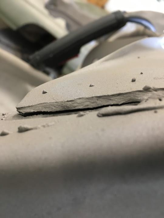
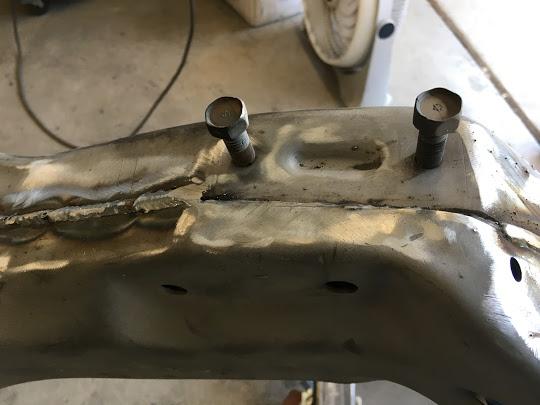
This was ground out, and rewelded. I went over most of the bottom of the frame and re-welded everything that looked suspect (which was damn near the whole thing). So while waiting for my stitch welds to cool, I decided to undertake another project. I've heard of several people who really push the A-Bodies with stiff sway bars, actually rip the sway bar mounts out of the frame. The stock threads are just punched steel that was threaded... So I started with this.
Made a cardboard template, just used a ball peen hammer to get the holes exact:
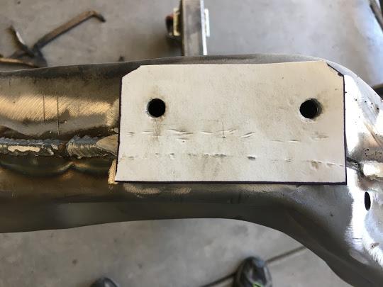
found some scrap 1/4 inch steel
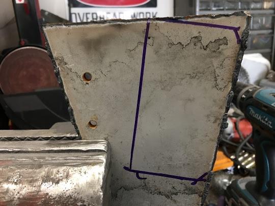
And after a little cutting, grinding, and more grinding, I ended up with this..
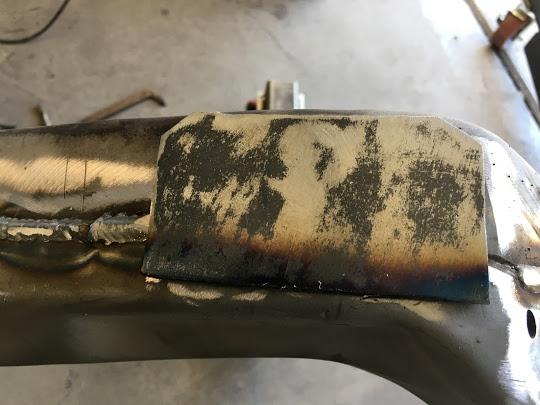
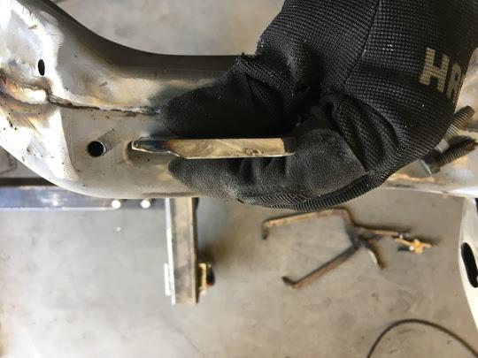
out came the hole saw to remove the stock attachments.
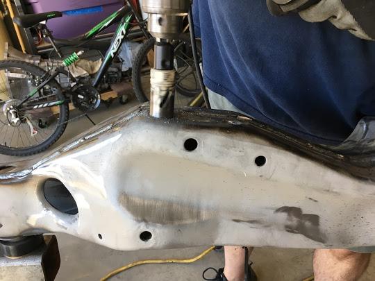
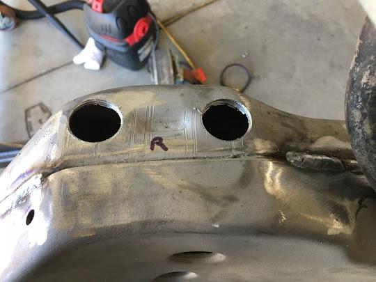
and I found some pretty beefy flange nuts in my bucket of junk that will do just fine...
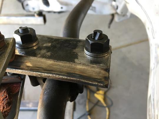
Those nuts got welded to the 1/4 inch plate, and the plate was welded to the frame.
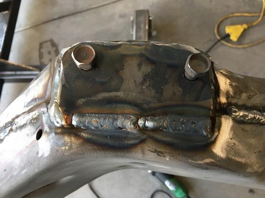
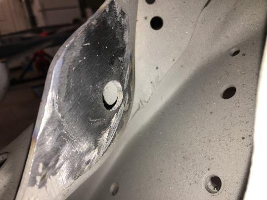
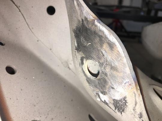
Also while waiting for the frame to cool, I found some damage that I wanted to repair for the front lower control arm brackets. These are the ones inside the front crossmember. It looks like the outer bushing tore into the steel. There was no real obvious wear on the control arms, or bushings...
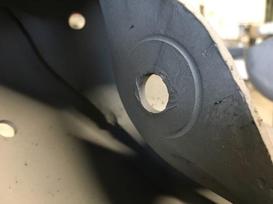
Strange thing is that the drivers side was WAY worse, and offset... The bushings in the control arms were in decent shape, so someone must have changed them at some point....
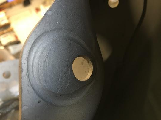
So I filled in the damage with weld.
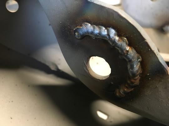
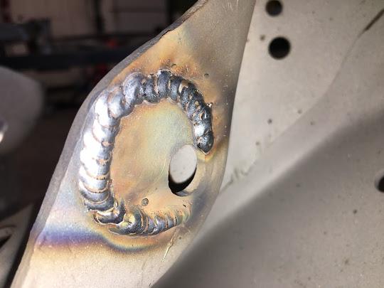
Then Ground smooth. I later used a file to make sure they were flush and smooth.
-
07-17-2017 #23
Registered User
- Join Date
- Aug 2008
- Posts
- 43
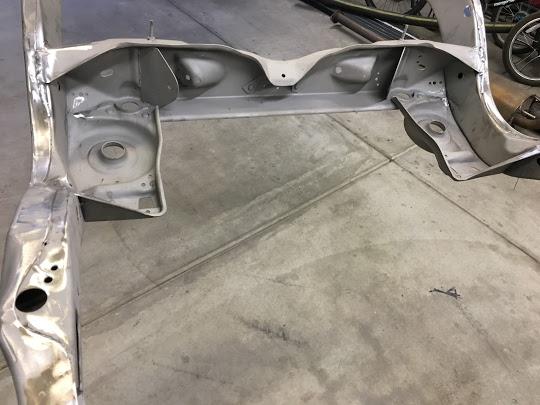
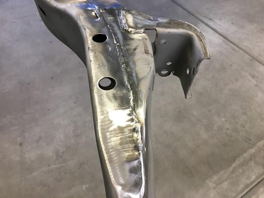
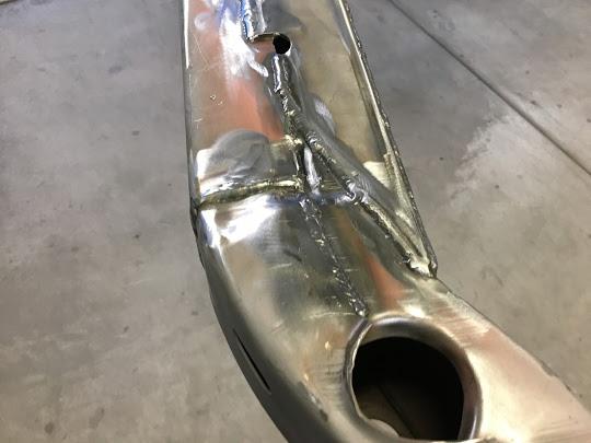
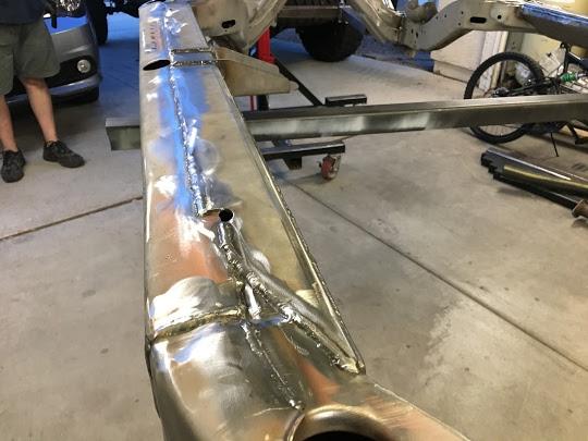
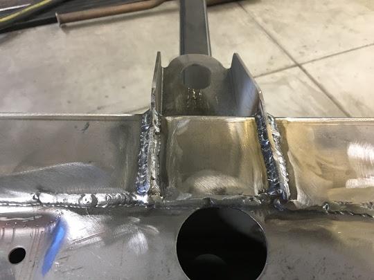
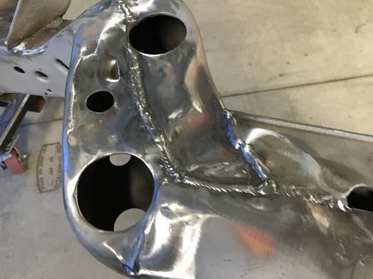
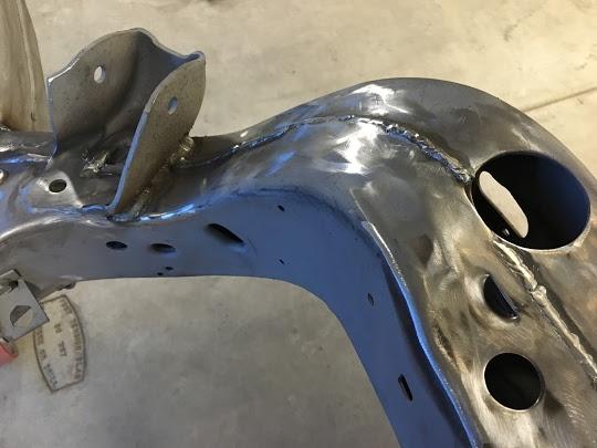
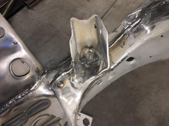
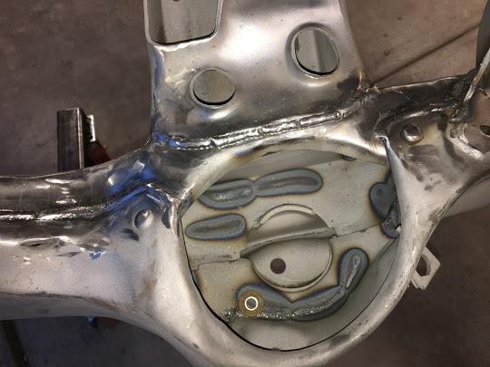
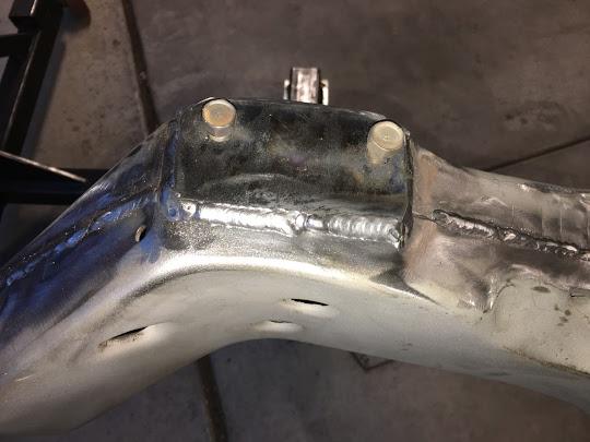
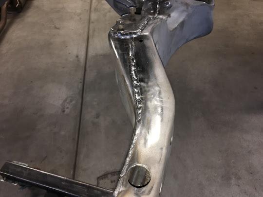
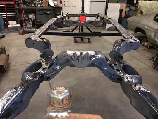
Here's the frame as it sits now. The bottom of the frame and the reinforcement kit is all welded solid on the bottom. All of the crappy OE welds are mostly extinct.
-
07-18-2017 #24
Registered User
- Join Date
- Aug 2016
- Posts
- 33
Lots of detail work man! You remind me of me ��. If I didn't do the little things while I was in there it would drive me crazy every time I looked st it down the road. Keep up the good work! This makes me upset that I was forced to send my '72 to the junk yard-title and all- due to lack of storage space. Funny thing is, When I went to the junk yard the next day to go buy it back ( without my parents permission - I was still in high school) the car never made it to the junkyard..... funny how that happened. That was 21 years ago and I'm still upset
 . Keep up the great work and I'll be watching
-
07-18-2017 #25
Registered User
- Join Date
- Aug 2008
- Posts
- 43
Finished up the welding today (HORRAY!!!!!). Found a couple more areas that could use reinforcements, so I took a few hours, went over the frame with a fine toothed comb and made sure there weren't any areas that I missed. After that was done, I went over the entire frame again and scuffed the surface, wire wheeled the welds, and generally got it cleaned up in preparation for epoxy primer...
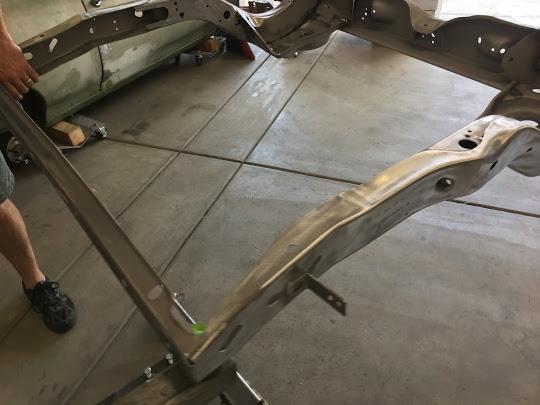
Welded nuts to the shock mounts (you see the bolt heads in this photo. This should make installing the rear shocks quite a bit easier...
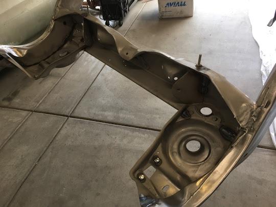
Here is the frame basically ready for primer.
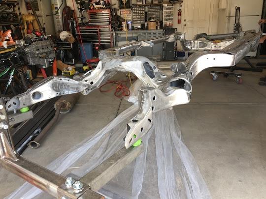
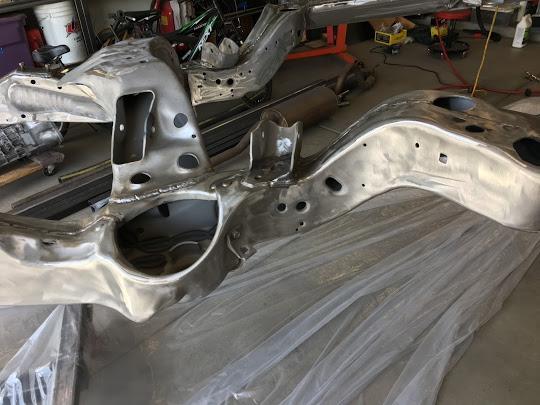
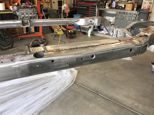
Primed...
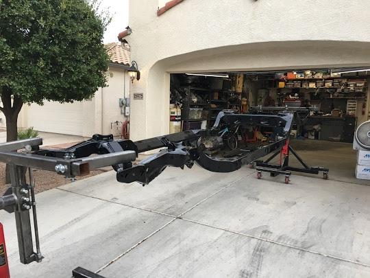
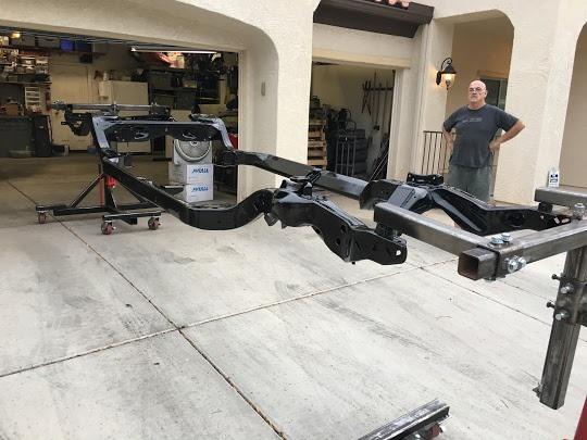
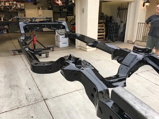
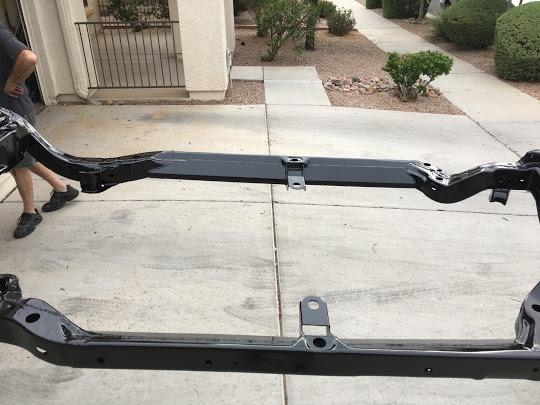
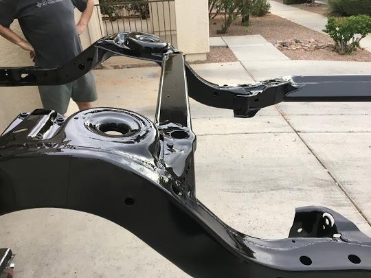
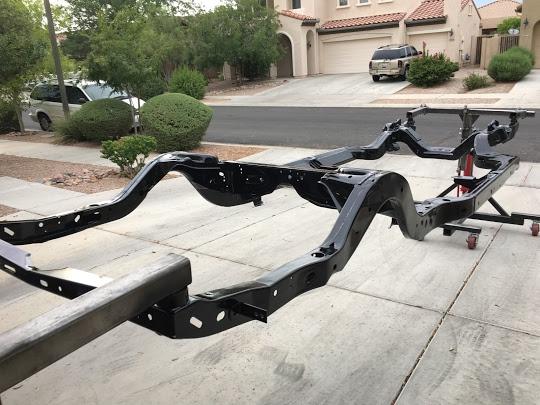
I'm back to work tomorrow and traveling and won't be back home until next week, so this will be tucked into the garage for a while. I have spent probably somewhere in the realm of about 30-40 hours total on this project if I include the original frame removal time (not counting the two weeks it took to sandblast the frame).
NOTE, I did not install the transmission crossmember kit that came with the Hellwig bracing. I will be fabricating my own mount...
If anyone has any questions about the kit, or the install, please let me know.
Steve
-
07-19-2017 #26
 Registered User
- Join Date
- Sep 2009
- Posts
- 3,003

Very interesting read, I appreciate going through builds with this much detail. Will check in on this for future progress.
1955 Nomad project LC9, 4L80e, C5 brakes, Vision wheels
1968 Camaro 6.2 w/ LSA, TR6060-Magnum hybrid and etc SOLD
1976 T/A LS1 6 Speed, and etc. SOLD
Follow me on Instagram: ryeguy2006a
-
07-19-2017 #27
 -Moderator/Sponsor-
- Join Date
- Apr 2001
- Location
- The City of Fountains
- Posts
- 16,129
Did you ever think about adding the Global West (or others) front coil over extension kits? I wish that was available when I did my chassis...
Andrew1970 GTO Version 3.0
1967 Cougar build
GM High-Tech Performance feature
My YouTube Channel Please Subscribe!
Instagram @dr__efi
I deliver what EFI promises.
Remote Holley EFI tuning.
Please get in touch if I can be of service.
"You were the gun, your voice was the trigger, your bravery was the barrel, your eyes were the bullets." ~ Her
-
07-19-2017 #28
Registered User
- Join Date
- Aug 2008
- Posts
- 43
I considered it, but decided against it. For right now, I'm planning on running conventional suspension with coil springs and shocks. (already purchased). If someday I decide to put coilovers on it, I don't mind taking the sheetmetal back off to add the suspension components. Originally Posted by andrewb70

Steve
-
07-19-2017 #29
 Starting The Transformation
- Join Date
- Aug 2015
- Location
- Heber City Utah
- Posts
- 167
Wow your getting it done !!!!
-
07-30-2017 #30
Registered User
- Join Date
- Aug 2008
- Posts
- 43
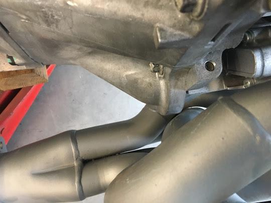
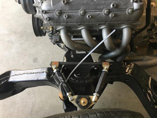
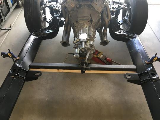
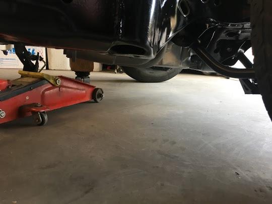
Spent the last few weeks doing family stuff, and helping my wife work on a Grad School project, so the car kind of took a back seat. I did manage to paint the inside of the framerails like I did the rocker panels in one of the earlier posts. The weather was pretty nice today only got up to about 99 today, so I spent some time helping my wife, then cleaning up the garage because it was a mess. After noon, I got the frame down off of the Rotisserie and started mocking up the front suspension. I got the engine and transmission bolted in, and now I'm on to building the transmission crossmember, so I installed the headers, and the AC Compressor to make sure that I didn't have to notch the frame, It's all good. Feels pretty good to have the frame more or less done, and the front suspension mocked up. After the transmission crossmember is done, I'll be running the brake and fuel lines. These AFX Spindles have been sitting in boxes for almost 8 years now in the garage. I forgot how nice they looked. I also attached the front rotors, and was going to mock up the brakes, but I didn't have the hardware to mount the calipers... I'll most likely wait until I buy the rear brakes which will be later this fall/winter.
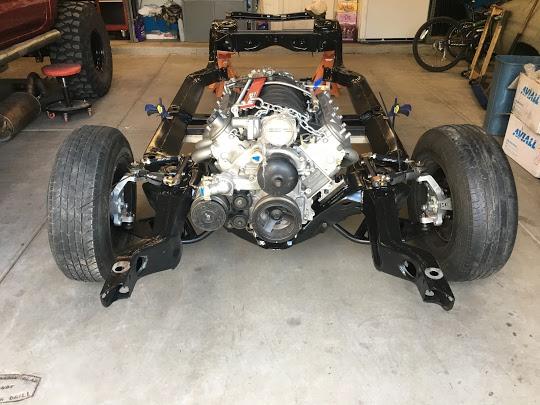
A question for all of you guys that are using the SPC upper control arms. At the Ball Joint plate, one of the attachment points has a bolt going through it, The other side is welded... I'm guessing that the welded link goes forward??? Also I'm not sure if I have the arms oriented correctly I have one where the bolts come from the bottom, and one where the bolts go in through the top. the pivot is a little different, where it's offset either high or low depending on how you mount he BJ.
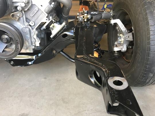
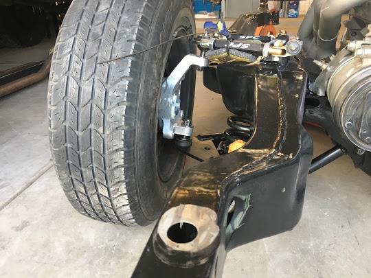
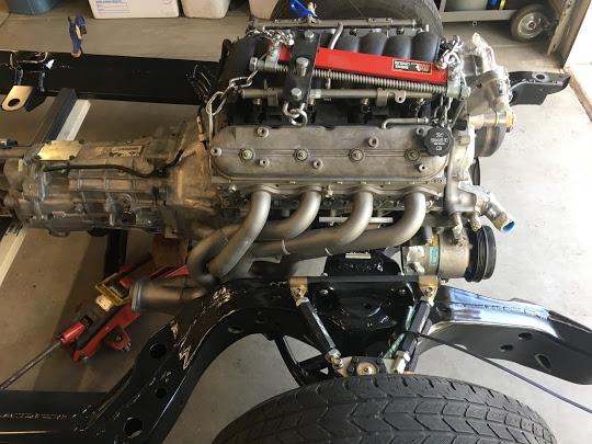
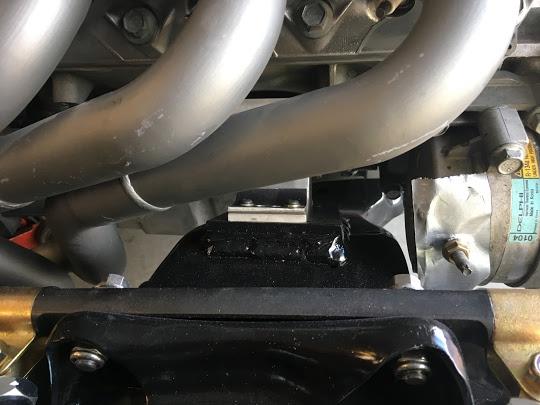
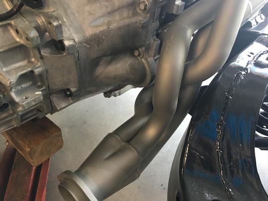
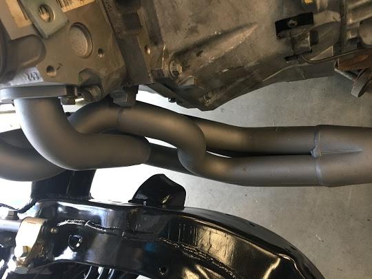
This is just the start of the crossmember, More to come...
-
07-31-2017 #31
 Registered User
- Join Date
- Nov 2006
- Location
- Ma.
- Posts
- 5,560
That's looking good, nice work.
Wayne
Car FINALLY home !!!!!! lol
Project FNQUIK https://www.pro-touring.com/showthre...ghlight=FNQUIK
-
07-31-2017 #32
 Registered User
- Join Date
- Sep 2013
- Location
- Houston, TX
- Posts
- 274
Deserttaco:
What a great thread, please keep posting such detailed pics. I'm building a '72 Olds 442 convertible and have the SPC upper arms on my front suspension. The SPC install docs state that the arms should be installed such that the longer adjusting arm (the one welded to the ball joint plate) is toward the front of the car. Keep up the good work!
RodneyRodney Meyers
72 Olds 442 Rest-mod clone
-
08-05-2017 #33
Registered User
- Join Date
- Aug 2008
- Posts
- 43
Another weekend, and a little more progress. Today I spent some time getting the mounts for the transmission crossmember build and welded in. I still need to weld the bottom of it, but I'll do that when I get it in a position to lift it up a little higher. Welding on my back in this heat is not going to happen... I'm pretty happy with the way these turned out, It'll allow me to easily install/remove the crossmember and let it be pretty strong too. The piece of 2X2 .120 wall tubing is just a mock up piece, the real crossmember won't be built until the chassis is back under the body so that I can make sure I get the transmission height right.
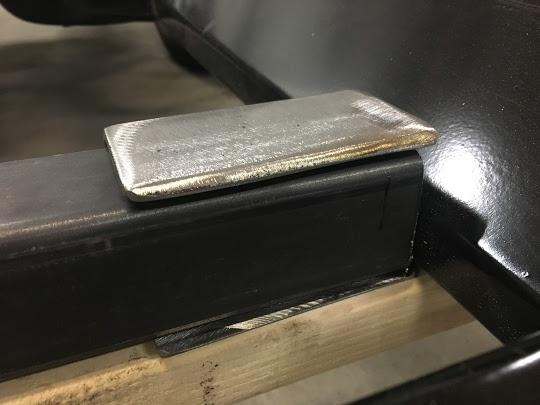
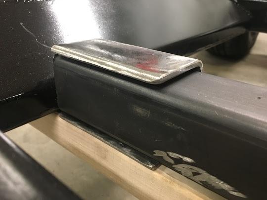
I used some cardboard templates to cut the 2.5X2.5 tubing so that it'd fit the frame profile, I also spaced these mounts up about .300 so that the bolt heads would be up above the bottom of the frame and there wouldn't be anything to catch on them. Didn't take any pictures of the CAD Templates, or the intermediate steps.
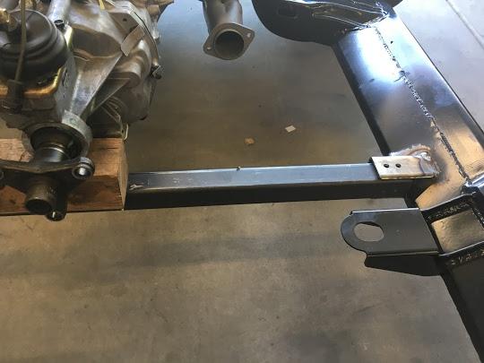
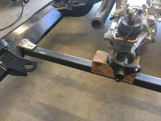
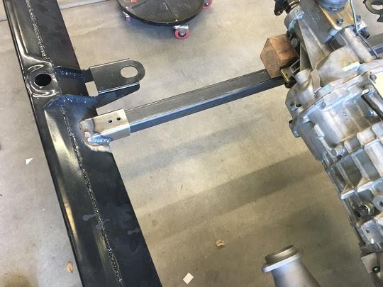
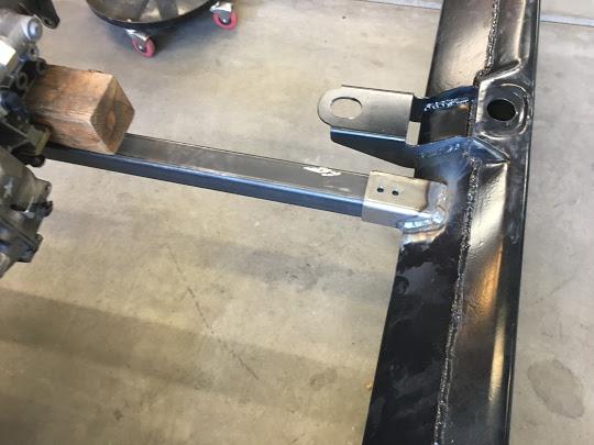
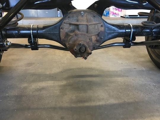
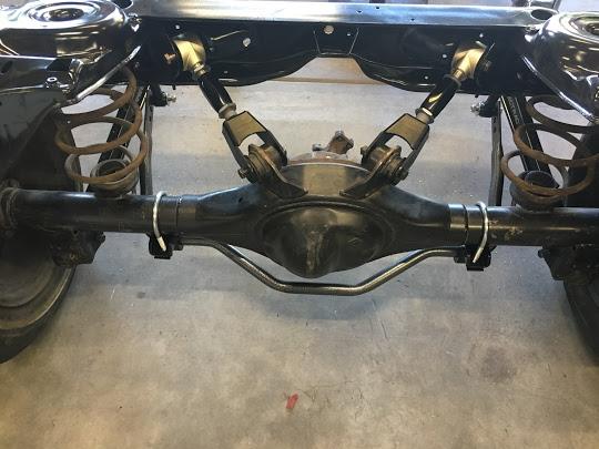
After that was done to my satisfaction, I decided to mock up the rear suspension and braces. I haven't purchased any rear springs yet, so I'm just reusing the stockers for the time being.
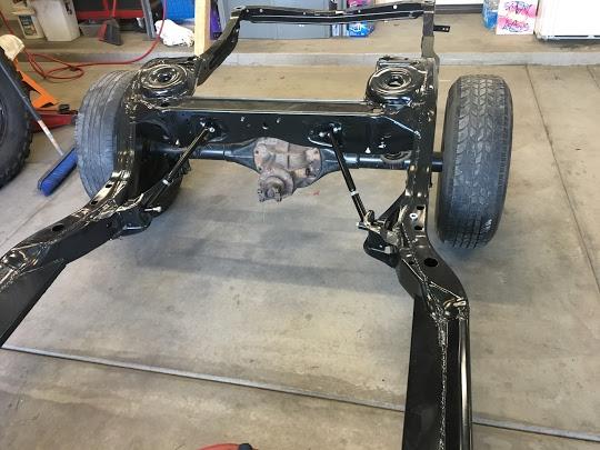
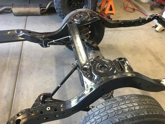
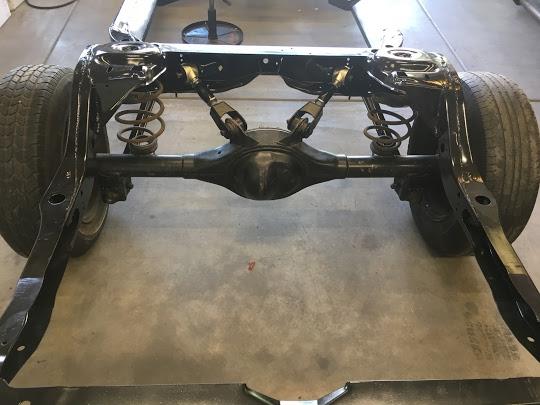
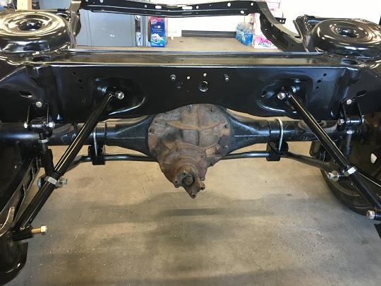
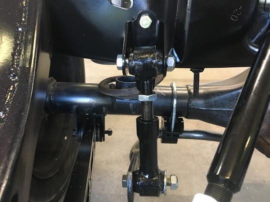
That actually only took me about an hour to put together. I decided to mock up the rear Hellwig Sway Bar. The kit and the instructions are actually put together pretty well, and the assembly only took about an hour and a half. It's a pretty nice kit and it's adjustable.
-
08-11-2017 #34
Registered User
- Join Date
- Aug 2008
- Posts
- 43
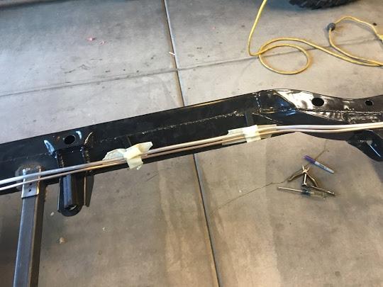
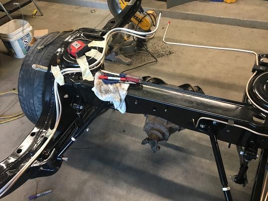
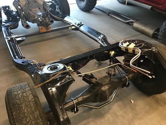
I am going to try to use the stock fuel tank modified to accept the fuel pump, bucket, sending unit, and EVAP system from a 2006 Pontiac GTO to feed the LS2 from the same car. I will also be using the stock master Cylinder, and booster from the same car. The brakes will all be C5 Corvette brakes, with a Wilwood proportioning valve. So there is NO off the shelf brake line kits that I can use for my car, and I wasn't about to cobble something together using almost 50 year old stock lines. Since I have the body and frame separated, I wanted to route and mount both the brake lines, and fuel lines prior to reuniting the two halves.
I probably spent WAY more on this system than what is actually required, but I'd rather do it right the first time than have to come back and redo something because i cheaped out...
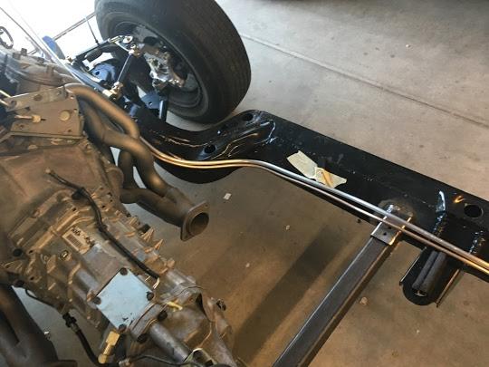
So to start: I choose to use the NiCopp Lines because they won't rust, and they are AMAZING to work with. I will be using Stainless gravel guard on all of the tubing just like the factory did. I decided to use 1/4 line from the rear axle to the proportioning valve. I'll be using 3/16 for the rear axle itself (not shown yet, need to wait until I get the rear parking brake parts and flex lines so everything lands at the right place. I'll be using 5/16 line for the LS2 EVAP purge line. 3/8 fuel line, and a 1/2 inch fuel line put there for future use if I ever upgrade the engine to something that needs more fuel. I have no interest in running flex line from front to back, Hard line is the way to go... I also splurged and bought the Mastercool flaring tool... This thing is amazing and well worth the money.
So first the lines...
I tried to use the coat hangers to mock up my bends... This sort of worked, but I ended up abandoning it after just a few minutes. I actually only scrapped about 20 inches of line due to a bender malfunction on the bigger diameter tubing.The benders were only used on the 5/16 and smaller tubing. The larger tubing was bent by hand. The tubing itself came in rolls of 25 feet, so I wanted to straighten it as much as possible before getting to far. There was a build here on this forum where someone built something similar so I stole the idea and made my own tubing straightener. only cost me about $8...
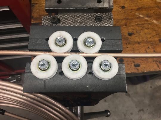
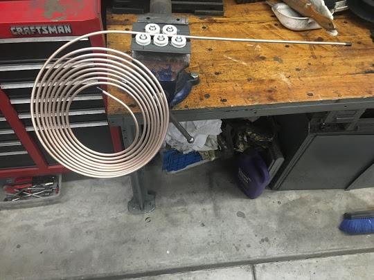
I used this same straightener for all of the different sizes of tubing... Worked AMAZING!
for hold down brackets, I went down to the local plastic shop, and asked the guy if I could poke around. I told him what I was working on, and he showed me this black plastic. He said it's the same stuff that milk cartons are made of, Pretty tuff, has a melting range of about 280 degrees, and cuts like butter... So I figured perfect for what I needed. I had them cut me 30 pieces that are 1/2" tall, 3/4 wide, and 4 and 1/4 long. I got the idea from a couple of guys in the UK building a Mini called project Binky... If you are ever bored, Check it out, really cool tech and lots of great ideas...
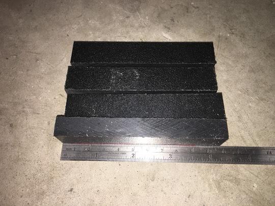
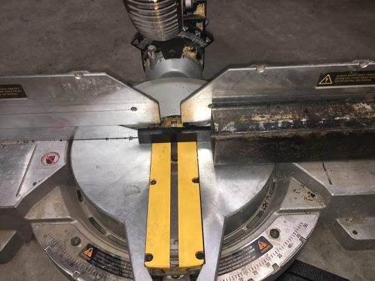
I cut these down a little more until they are about 2 inches long just using a wood blade on my saw.
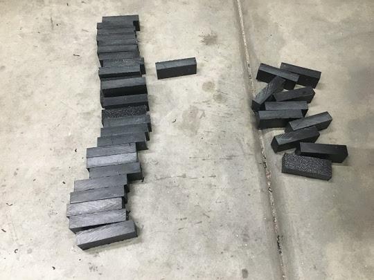
Set the pieces on their end in my vice and with the drill press, I drilled a 1/4 inch hole in one side, and a 5/16 hole in the other side.
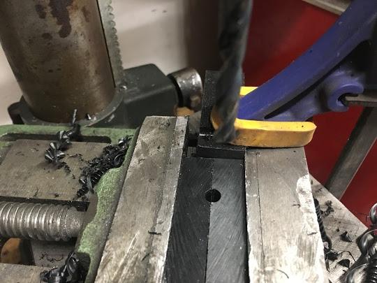
Then set them straight up in the vice, and using a Forstner bit I cut the recess for the bolt heads.
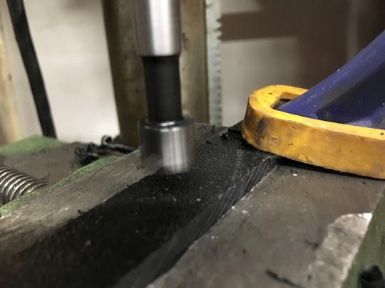
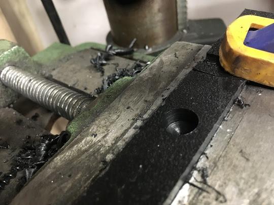
Then drilled the rest of the way with a 1/4" bit for the bolt through.
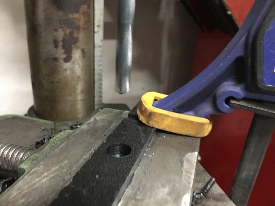
So here's a mock up of what it looks like. The bolt head is flush with the top, and the bolt extends just enough to go down through the frame.
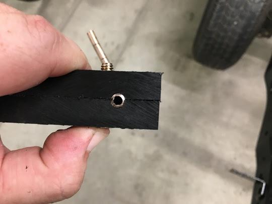
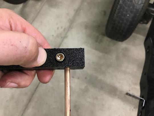
I tried to mimic the stock lines where I could, but since I'm changing so much with the car, and don't ultimately know where the lines are going to land, I have an unknown factor here, so a lot of the lines are run long to accommodate changes when the body and chassis are reunited. Anyway here are the rest of the pictures.
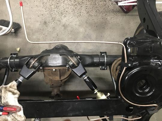
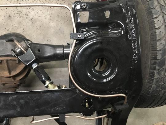
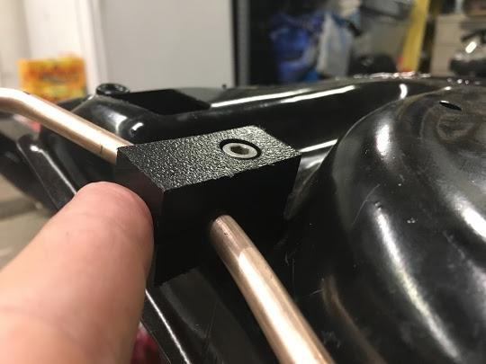
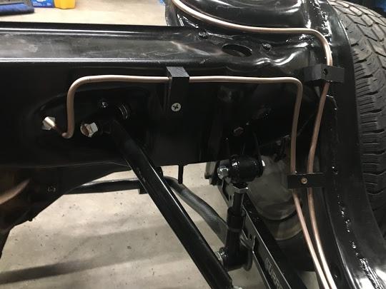
Don't pay attention to the mismatched hardware... This is simply a mock up, the hardware will all be changed to the correct hardware upon final assembly, and after the gravel guard is installed.
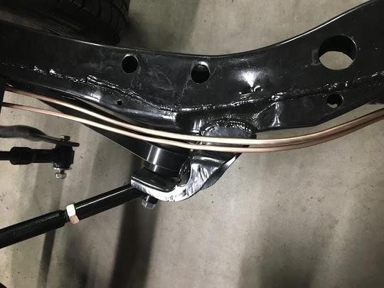
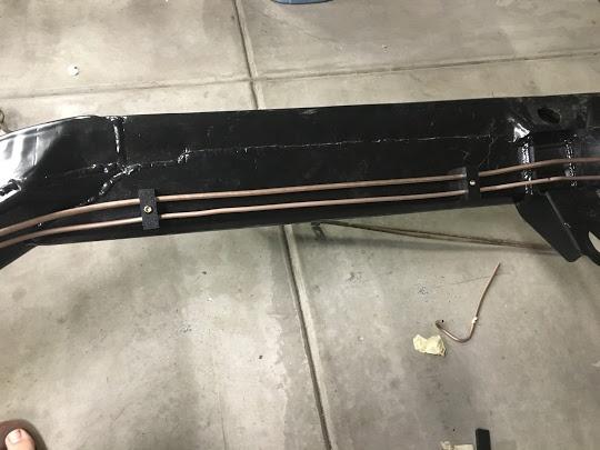
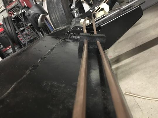
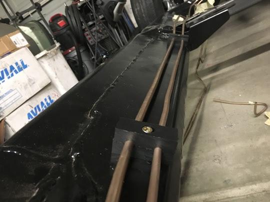
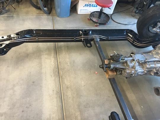
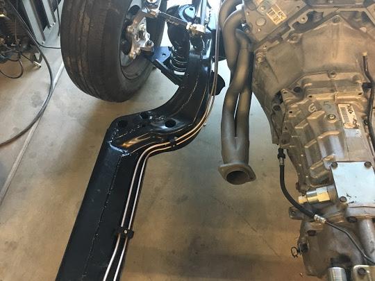
The lines go straight to the end of the frame. I'm not sure where the final position of the proportioning valve will be, and won't determine that until the body is reinstalled.
The Fuel lines for now are just sitting there. I'm hoping that tonight or tomorrow, I'll be able to build the brackets for these, and get them installed. I'll update these pictures as soon as they are done.
-
08-11-2017 #35
 Registered User
- Join Date
- Mar 2015
- Location
- FL
- Posts
- 318
Just saw this thread for the first time. WOW is all i can say and it's not nearly enough. So I'll add this



Looking forward to seeing this thing come together.-Mitch
G8 GXP, White Hot, Auto, bone stock
68 Firebird, 428 Pontiac, CNC'd KRE Al d-ports, hyd roller, EFI, TKO600, TCI Eng complete chassis, Ridetech, Kore3 C6Z brakes, C5Z 18" with 315 rivals x4, C6zr1 mufflers
RRR, NASA HPDE https://youtu.be/DPp1l9-FuNE
-
08-12-2017 #36
Registered User
- Join Date
- Sep 2013
- Location
- Houston, TX
- Posts
- 274
EFI tank and fuel pump
Deserttaco:
I read your post with your fuel system plans. The '06 GTO fuel pump may be too tall to fit in the Chevelle tank. A 5th gen LS3 Camaro pump is a great OEM alternative that will fit depth-wise and will run on a pwm power feed for lower fuel temps and quieter operation. One big obstacle is the 5th gen mounting flange is very large so tank mods are required or you need to purchase a RestoMod tank from Rick's Tanks that already has the 5th gen pump mounting ring. I chose the RestoMod tank from Rick's.
Vetteworks makes a fuel pump mount for the 5th gen pump that can be welded into a stock tank or a custom tank if you decided to go this route. I bought a kit from Carl at vaporworx (Carl is a member here) that allows me to run a return-less EFI fuel system (I think this is called a dead-head system). If you install a 4th gen poppet valve in the 5th gen Camaro pump you can bypass excess fuel in the tank to regulate the fuel pressure to 58psi and run a single line to the engine - no need for a bypass regulator under the hood or a return line. My HP needs are less than 400HP so this will work great for my throttle body EFI set-up. Carl has other kits for higher HP levels and stand-alone PWM controllers if the factory ECM can't run in PWM. Here are a few pics of my parts:
5th Gen Pump and 4th Gen Poppet Valve
RestoMod Tank from Rick's Tanks
Vetteworks Fuel Pump Bucket
Rodney Meyers
72 Olds 442 Rest-mod clone
-
08-12-2017 #37
Registered User
- Join Date
- Aug 2008
- Posts
- 43
Rodney,
Thanks for the information. I have been poking around and considered the Ricks Restomod tank. It's a pretty awesome tank, but I'm going to try to use what I got. I have the stock '06 GTO tank with sending unit, pump, and all of the plumbing required. The GTO tank is a bit taller than the Chevelle tank, but there was a guy on LS1Tech that took a GTO pump and cut down the standoffs. That's what I'm planning... If it doesn't work, then I'll take a look at the Camaro pump module. I was planning on cutting the top of the GTO tank and grafting it to my stock Chevelle tank. Hopefully I'll post pictures by the end of the year of that.
Steve
08-13-2017 #38
Registered User
- Join Date
- Aug 2008
- Posts
- 43
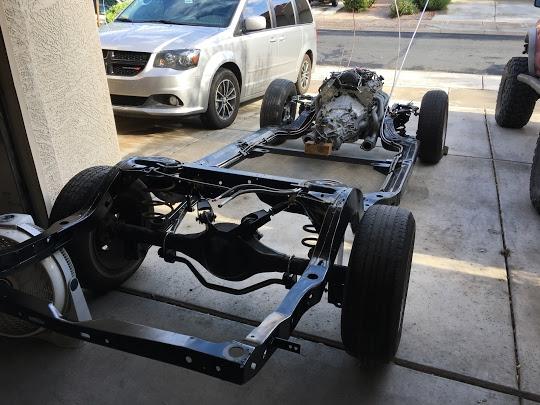
Big day today. I got just about all of the frame work done, Just have some primer touch up to do, and that'll all be done right before I reunite the body and frame. So the frame and chassis were mothballed, and I pulled the body out with the hopes of getting it on the rotisserie. It rained ALOT here last night, so it was only 75 degrees this morning, so I was up and out in the garage at about 0630. The frame got pushed out into the driveway first, and I tried to move a bunch of stuff around to give me a lot of space.
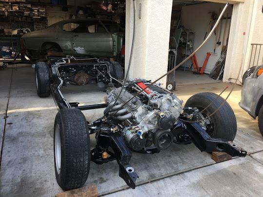
I moved the body back over, and got it up high enough to get the rotisserie arms attached to the body mounts. The rear mounts were pretty easy to use, the front mounts were wider, and I had to extend the rotisserie arms out to be able to utilize the mounts.
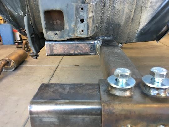
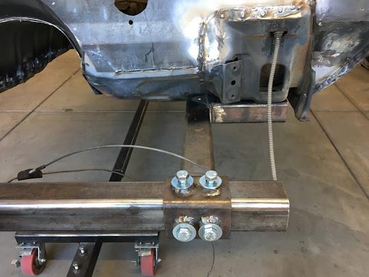
And like that, It's on...
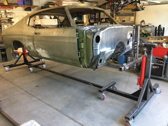
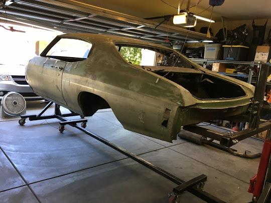
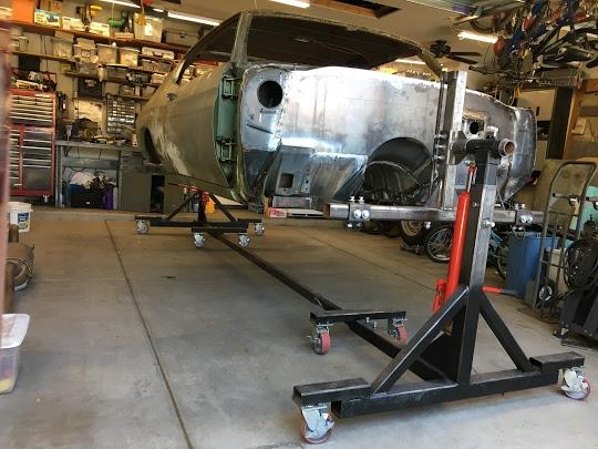
Took me about 20 minutes to get the balance just right. Now everything is locked down and I can spin it pretty easily by myself. When I let it go, it stays where I have it without moving.
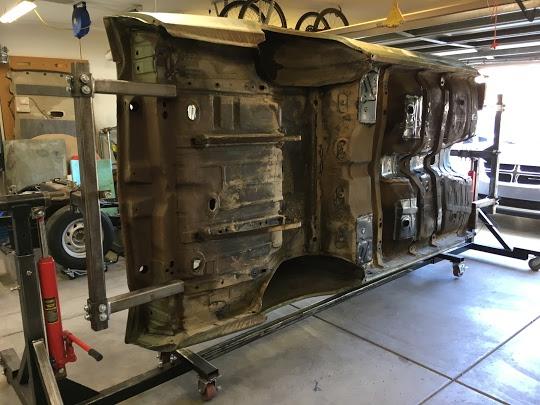
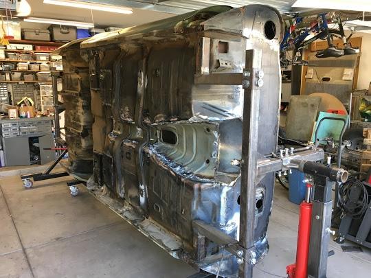
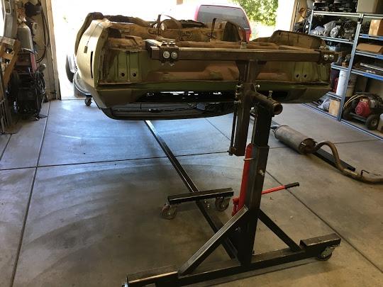
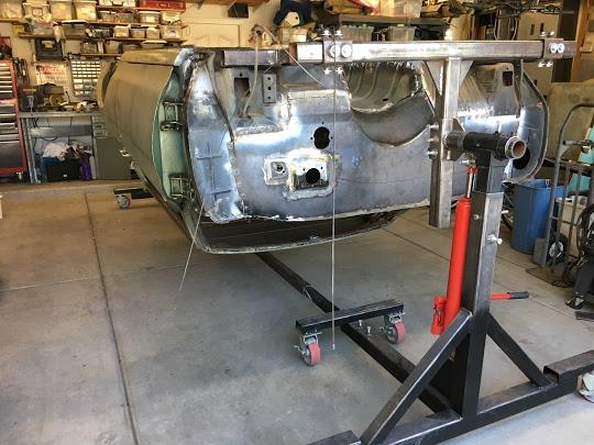
https://youtu.be/Ym84aBsrov4
08-27-2017 #39
Registered User
- Join Date
- Aug 2008
- Posts
- 43
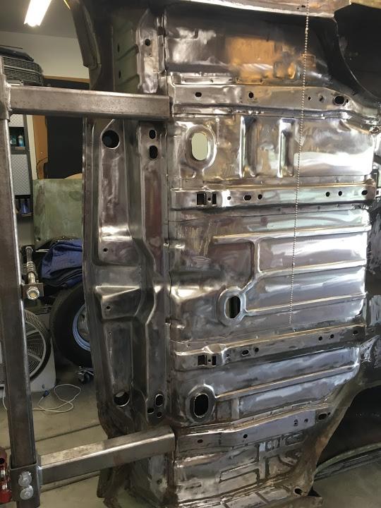
Over the past two weeks, I've been working on cleaning up the bottom of the car in preparation for the seat mount bracing, and to finish off the transmission tunnel, and the Floor Bracing. There's a part of me that wishes that I just took the damn thing to the same sandblaster that I took the frame to, but didn't want to spend the coin, and wanted to do this in steps.. Plus I didn't want to be cleaning blasting sand out of every crevice for years... This was all done with wire wheels, 3M Bristle disks, and lots of time and patience....
This is a good pic of what I started with. No really rusty areas except the very back of the car from the three holes in the trunk pan back. This area was pretty rusty. There is no rot here, just some pretty thick surface rust. The rest of the floor had 50 years of road grime, there was some undercoating in the wheel wells, and a few other areas on the floor.
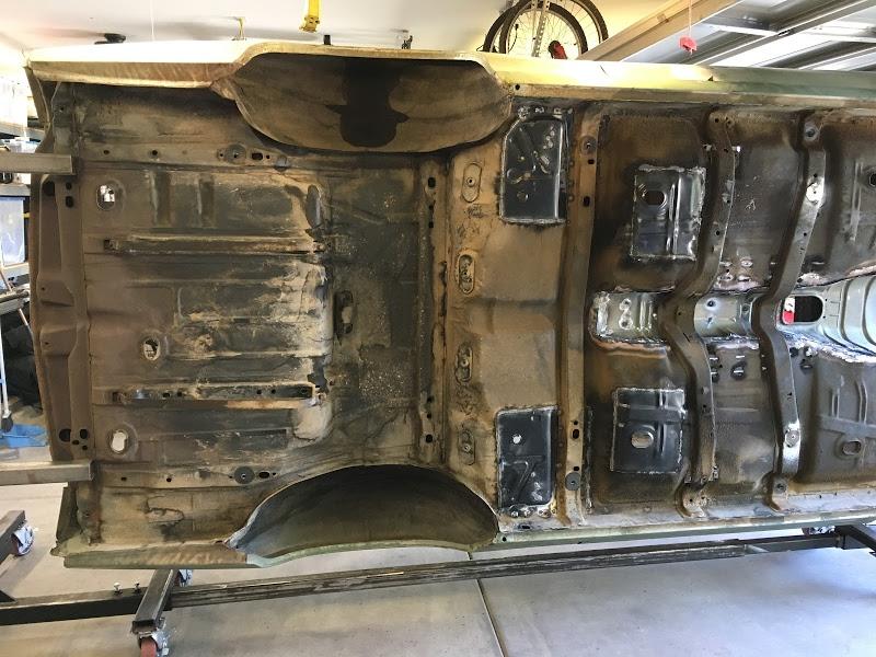
Here's the extra body mount from the Hellwig kit. The surrounding floor pan is a pretty good representation of what the rest of the floor looked like up close. Lots of crap, the OE black paint/primer, and lots of clean sheetmetal.
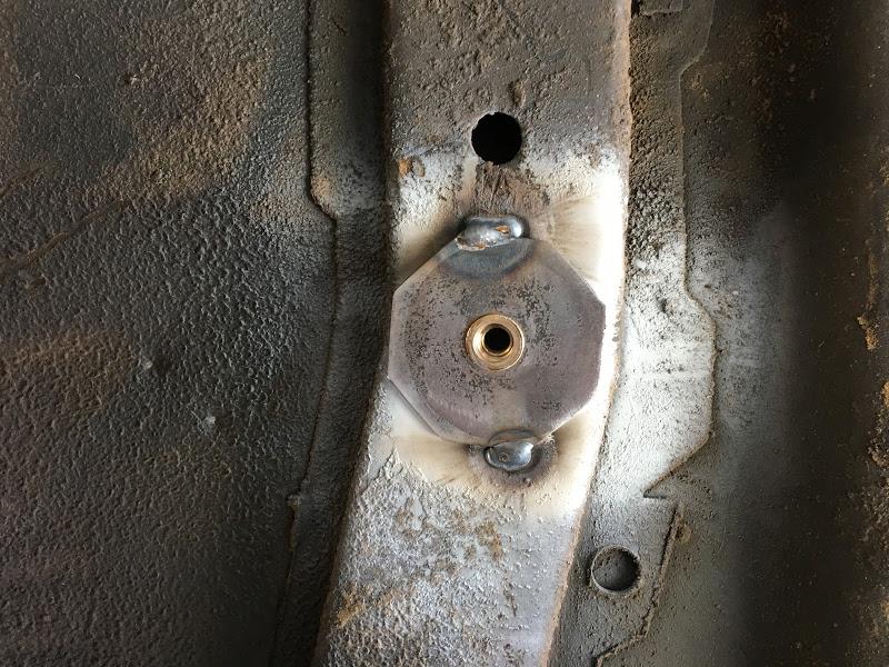
In this picture you can see the amount of extra space I will be gaining with the GTO tunnel. The OE Floor brace will be removed and replaced with a section from the GTO Brace.
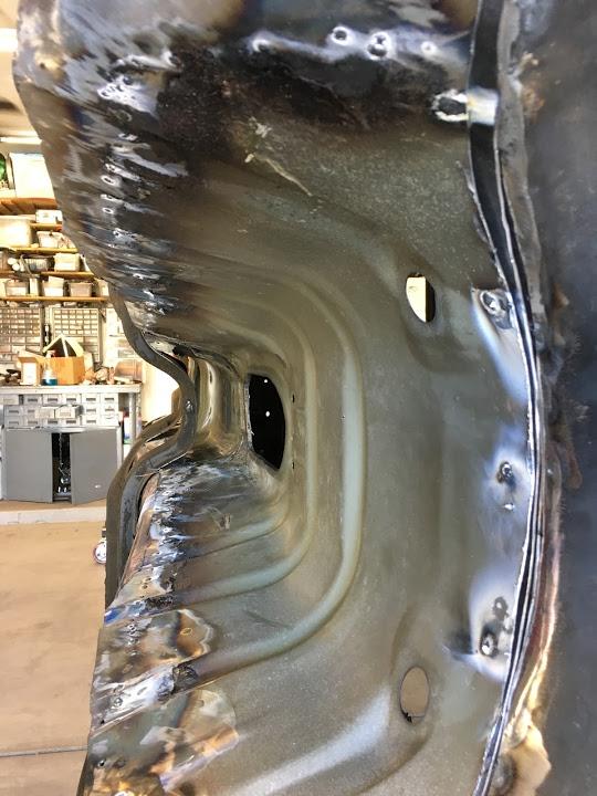
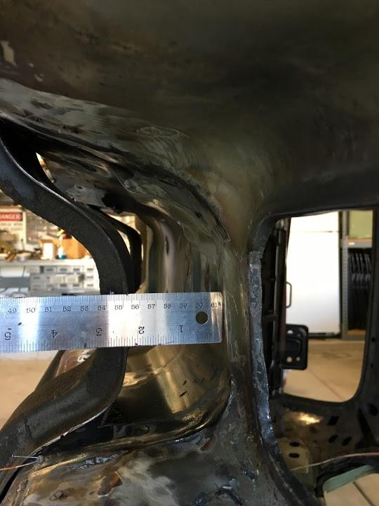
Here's how it looks now... I still have some clean up work to do around the edges... Still need to work on the wheel houses, and a few areas around the rear floor brace... The rust in this area pictured below was THICK! Just from those holes in the trunk pan to the tail panel probably took the majority of the time.
I did unfortunately find a little bit of rust in the bottom of the quarter... I'll have to cut this out and repair it...
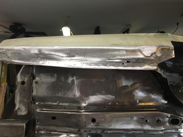
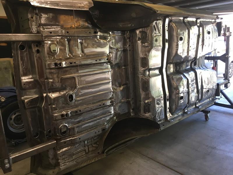
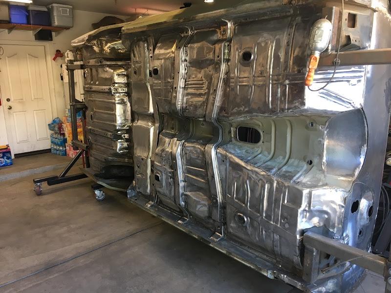
Over the next 2-3 weeks, I'm hoping to finish cleaning up the bottom of the floor (including the wheelhouses), build and install my seat mount bracing, Remove the floor braces where the attached to the Original tunnel, and install the GTO braces. Then finish welding up the transmission tunnel. Hopefully after that, I'll be able to get the sound deadening on the bottom of the car, and the heat shield. I'm planning on Lizard Skin both the sound, and the heat coatings under the floor, and on the roof.
Steve
09-06-2017 #40 Registered User
- Join Date
- Jun 2012
- Location
- N. Shore, Ma
- Posts
- 346
Nice job cleaning up the underside of the body, had to do that twice to my GTO. Even after it was sandblasted it was lots of work to prep for paint.
Eric
Building 1969 GTO - Roadster Shop chassis, LQ9 w LS3 heads and rebuild parts from TSP, Bowler prepped Magnum T56 6 spd, 3 Link Strange 9" w Speedway Floater Hubs, Wilwood 14" F - 13" R brakes, 275.18 - 345.19
https://www.pro-touring.com/threads/94970-69-GTO-Build

 Reply With Quote