


Results 61 to 80 of 146
Thread: chassis jig design
Hybrid View


-
04-10-2008 #1

 Registered User
- Join Date
- Nov 2005
- Location
- Motorcity, Canada
- Posts
- 292
Kevin - that is quite the setup!
After doing some welding, I did decide to add some cross braces, just to ensure it does stay true. Amazing what steel will do with heat! The tubing I am using is 3"x3"x .25", so it is fairly stiff. The cross bracing is mainly to ensure the structure keeps its shape after welding, and will provide more stiffness to the system (although not the intent). I will meet you halfway with bracing David . The way I can still get the creeper under the car with no issues. It also worked out with some extra shorter 2"x2"x3/16" material I had on hand. The braces will be stitch welded on, and then the legs will be fully welded after that.
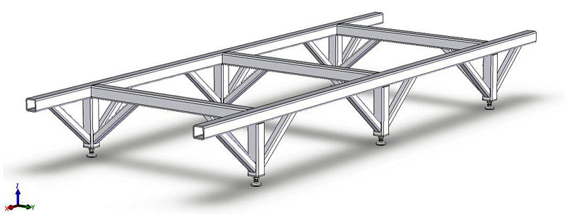
I did run FEA on the original piece, and even if I load up the jig between the posts will 4000lb (1000 each spot), the deflection is a fraction of a mm, and this also takes into account that it is not bolted to the floor and is free to pivot about the floor. I will have to re-run with the new braces.
I have it almost done - I will have to post more pictures. I am hoping to have this under my car within the week.
-
04-11-2008 #2 -Moderator-
- Join Date
- Apr 2001
- Location
- Central CA USA
- Posts
- 6,114

That looks good.
I'm not so concerned about load, but just the welding heat from welding on the legs causing warping of the main tube. I'd go very easy when welding on any braces, use low heat and just skip weld them on. The braces don't need to be as thick as the main tube.
DavidDavid Pozzi http://www.pozziracing.com67 Camaro RS that will be faster than anything Mary owns.
04-12-2008 #3
Registered User
- Join Date
- Nov 2005
- Location
- Motorcity, Canada
- Posts
- 292
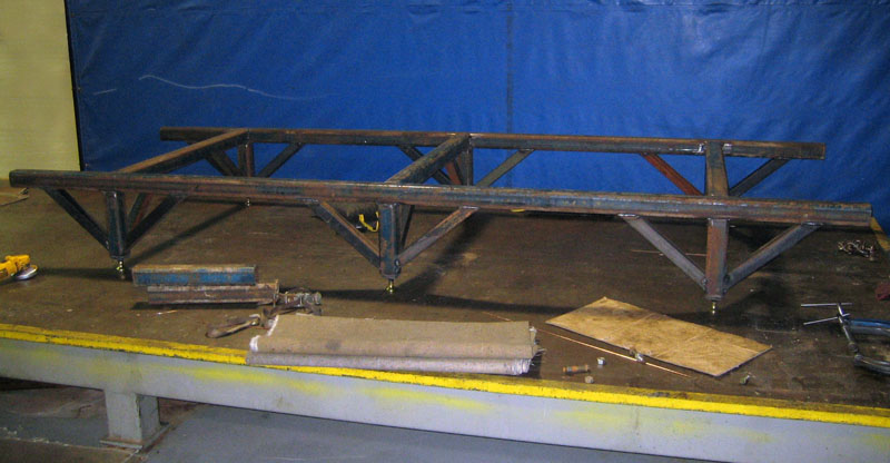
Almost there.. there was minimal warping with this method, although there was a bit on the short overhanging end pieces. Will have to reverse this by some heat and force on the ends. Nothing major though. Had to brush up on my MIG skills as I have only been using TIG for while now. TIG would just make the warping much worse.
The braces are thinner walled than the main pieces - just extra material I found sitting around. Should have this up and running under the car within the week.. can't wait. The Carr-Lane leveling feet (part CL-8-SLF) work perfect.
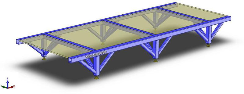
Also set this up so I can put an 1" thick or so sheet of plywood in between the braces to drop the plumb bob on. A 4x4 sheet will fit exactly in between the two middle sections.
07-03-2008 #4
Registered User
- Join Date
- Jul 2008
- Posts
- 4
I don't understand how TIG would make heat input worse than MIG???? Originally Posted by SVTforme

You have a foot pedal to control heat with TIG. Care to explain???
07-03-2008 #5
Registered User
- Join Date
- Apr 2006
- Posts
- 1,027
with tig, you have constant heat going into the weldment, where with mig you cant stich weld it to keep heat to a smaller haz
07-03-2008 #6
Registered User
- Join Date
- Jul 2008
- Posts
- 4
Well i guess i have to know what sort of TIG you would be using b/c what you said just doesn't make sense to me. Wether you MIG for 1in and then skip 2in weld 1in and keep repeating that pattern. Once the trigger is pushed your a Xamps. With TIG (I have a Miller Dynasty 300DX) you can set the pulse, background current, etc..etc. Heck at the very least you can rock the pedal.....
04-12-2008 #7
-Moderator-
- Join Date
- Apr 2001
- Location
- Central CA USA
- Posts
- 6,114
That came out very nice, but please paint that thing!

I need to build one.
DavidDavid Pozzi http://www.pozziracing.com67 Camaro RS that will be faster than anything Mary owns.
04-15-2008 #8
Registered User
- Join Date
- Nov 2005
- Location
- Motorcity, Canada
- Posts
- 292
No worries there. In a couple of days once I get it back home it will be Miller Blue to match the welders
.
I debated back and forth on whether or not to build it, but glad I did. The steel used to be a billboard on the side of the road and someone posted for sale on Craigslist. This helped to make it cost effective. The adjusters were expensive but work excellent and well worth the cost. Not sure what I am going to do with the jig when not in use, aside from having it take up valuable room. Guess that means I will always need a project car on the go.
Hopefully the next post I have will be with a car bolted to it.
05-12-2008 #9 Registered User
- Join Date
- Nov 2007
- Location
- northern california
- Posts
- 388
took a little longer than expected- steel is rediculous right now- Il ad fixtures as i can afford them

Scotts Speed and Custom
norcal1320.com
05-12-2008 #10
Registered User
- Join Date
- Nov 2007
- Location
- northern california
- Posts
- 388
we basically made adjustable legs out of 4x4 1/4 wall which was bigger than needed but we got a deal on it. Then found those adjustable feet on craigslist for $75. The casters are rated at 1400lb a peice and were picked up in a catalog for $100. At first we welded the center leg on but have since cut it off since it bottoms out when you push it in and out of the shop. To make sure the I beams were on the same plane we used our fab table which we thought was flat until the machinist next door let us borow his 8 ft straight edge. After about 5 hours of shimming and adding alot more bolts and shimming some more we finally got it flat and level. THe next hurdle was both i beams were warped. If i had to do it over i would have bought some more 4x4 for the top rails. I wanted to use i beam since it makes clamping things to it easier. Anyway we started with the straighter of the two i beams and tacked it to out fab table and used a portapower and ratchet staps to true it up. We welded the center leg to both i beams and then spent another 5 hours tweaking and muscling the send i beam true to the first. Its not perfect but within 1/16th of an inch. At this point its a good table top to start with. I picked up some 2x6 1/4 wall to lay across the i beams under the wheel base, as well as some huge c chanel my buddy had at his work to make some spindle fixtures. As money permits i would like to plate the surface and have a fixed centerline like the one pictured above.
Thanks to all who posted pics and design ideas. Ill post some updaes as we add to itScotts Speed and Custom
norcal1320.com
06-07-2008 #11
-Moderator-
- Join Date
- Apr 2001
- Location
- Central CA USA
- Posts
- 6,114
Thanks for the photos! I was thinking of doing something similar, or I do have an old truck that I could strip down for a piece of the frame, then add legs and perhaps lay a pair of I beams or square tubes on top of them if it's not flat enough.
DavidDavid Pozzi http://www.pozziracing.com67 Camaro RS that will be faster than anything Mary owns.
06-07-2008 #12 Registered User
- Join Date
- May 2002
- Location
- Northern California
- Posts
- 10,716
Looks good Scottzilla. Did you go through Northern for the casters? Those roll nice.
!!Off topic!! but did a guy named Steve get in touch with you yet? He bought my 69 Nova and he wants to do an LS/T56 swap but im swamped. He's in your area. BTW, hows business been?MrQuick ΜΟΛ'ΩΝ ΛΑΒ'Ε
06-22-2008 #13 Registered User
- Join Date
- May 2007
- Location
- Houston, Tx
- Posts
- 2,200
this has helped enormously reading through it all...thanks to everybody who has contributed!
Colin Russ
08-15-2008 #14
Registered User
- Join Date
- Aug 2004
- Location
- Dunwoody, GA
- Posts
- 4,983
so after welding the jig together, how do you determine if it's warped, where it's warped, and by how much? You have to measure from somewhere that's known to be true, correct? Thanks guys
Trey
"The early bird may get the worm, but the second mouse gets the cheese."
~ Jon Hammond
1979 WS6 Trans Am stock LT1/T56 drive train out of my Formula. BMW M-parallel rims. C5/C6 brakes
build thread https://www.pro-touring.com/showthre...ghlight=begins
01-20-2009 #15
-Moderator-
- Join Date
- Apr 2001
- Location
- Central CA USA
- Posts
- 6,114
Trey, Originally Posted by WS6

The easiest way would be to get a laser and set it up in the middle of the jig table then stand a ruler up at various points along the table to verify them. If the laser won't shoot 360 degrees around, then put it to one side of the table. The idea is to place the level off to the side of the center of the table, not on one end. It is slightly less accurate if placed on one end but not by much. Of course the laser has to be carefully leveled. I have a survey transit I can use.
I think if I had a welded-up jig table, I'd bolt on a top rail to it to be the level surface. That way the table supplies the rigidity, but the top rail can be bolted on level and won't be warped from welding heat.David Pozzi http://www.pozziracing.com67 Camaro RS that will be faster than anything Mary owns.
01-20-2009 #16 Registered User
- Join Date
- Feb 2006
- Location
- Idaho Falls, Id
- Posts
- 1,341
^^ I was just looking at 360* laser levels today lol.
I've been wanting to make a bench out of I beam and I just told my dad the other day to keep an eye out for about 30' of 12". He said......"you know, I think I saw some in the paper recently and wondered......who the heck would want some I beam"
shoulda told him sooner Traven
02-15-2009 #17
Registered User
- Join Date
- Aug 2004
- Location
- Dunwoody, GA
- Posts
- 4,983
Thanks for answering this David. I hadn't thought of a laser level. Everything I did thing of required knowing the accuracy of it's surface, ie measuring from the floor up or some how running a dial indicator over the top. This makes perfect sense though Originally Posted by David Pozzi
Trey
"The early bird may get the worm, but the second mouse gets the cheese."
~ Jon Hammond
1979 WS6 Trans Am stock LT1/T56 drive train out of my Formula. BMW M-parallel rims. C5/C6 brakes
build thread https://www.pro-touring.com/showthre...ghlight=begins
05-17-2009 #18 Registered User
- Join Date
- Nov 2008
- Posts
- 63

Subscribing!
05-17-2009 #19
Registered User
- Join Date
- Nov 2005
- Location
- Motorcity, Canada
- Posts
- 292
If I had to do this all again.. I would definitely bolt the top rails to the legs rather than welding (since you only put heat into the bottom of the main rails when welding). I should have listened to David in the first place. Originally Posted by David Pozzi
. Instead I had to use the torch and play the trial and error game until everything was flat. It was a pain!
In the end, having my own chassis fixture for under $250 was the best thing I could have done for my project. It saved a lot of time and took most of the guess work out of positioning components on the car.
I ended up using a surface plate to true mine up. Worked like a charm.. but only really useful if you have access to one.
10-08-2008 #20
-Moderator-
- Join Date
- Apr 2001
- Location
- Central CA USA
- Posts
- 6,114
I have a question on table length.
I can get a truck frame for free and am thinking of making a frame table out of it. It will be super heavy and a bit narrow but I have a forklift and can place square tube sections across it for more width. This thing is STOUT! allready has crossmembers riveted in and the frame is double thickness!!!
I'm thinking that to do a Camaro you need 14' to 15' long? I can always cut some off the ends if it's too long.
Thanks, DavidLast edited by David Pozzi; 10-08-2008 at 05:49 PM.
David Pozzi http://www.pozziracing.com67 Camaro RS that will be faster than anything Mary owns.

 Reply With Quote