


Results 1 to 20 of 31
Thread: Guldstrand Mod Templates
Hybrid View


-
01-30-2017 #1

 Registered User
- Join Date
- Jan 2011
- Location
- Boston, MA
- Posts
- 1,180

Guldstrand Mod Templates
I'm thinking about doing the Guldstrand Mod while my front end is apart and googled "Guldstrand Mod Templates" and came up with a couple of options.
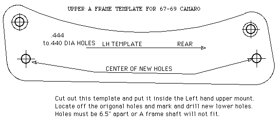
From http://www.pozziracing.com/first_gen...sion_geome.htm, this template lowers the front hole by 1.060" and rear hole by .775" and moves the holes .25" to the rear:
From http://www.auto-cross101.com/Guldstrand_s_modifed.html, this template lowers both holes by .75" and moves the holes .25" to the rear:
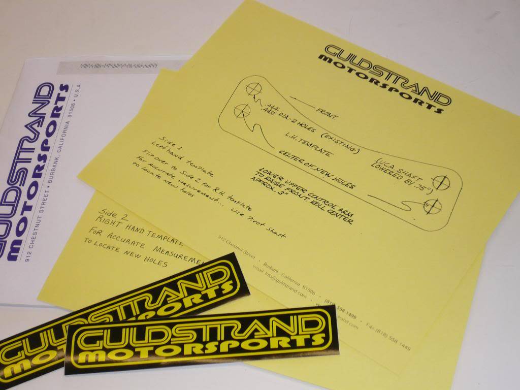
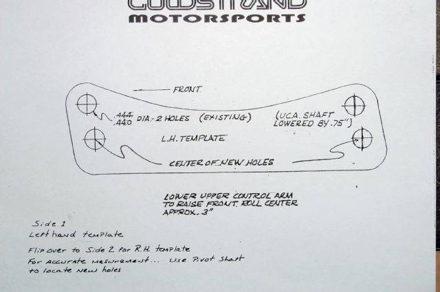
I believe this is the same template as above, different pic:
And on Pozzi's site there was mention of an employee of Guldstrand (Chicane67) that said the front hole is lowered by .875" and the rear by .775", no mention of moving the holes rearward.
Can the experts chime in and discuss what kind of effect the different hole locations would have and which template people are currently using? Thanks.
-
01-30-2017 #2
Registered User
- Join Date
- Nov 2014
- Posts
- 39
Subscribed, preparing to do this myself, wondering the same thing...
01-31-2017 #3
Registered User
- Join Date
- Mar 2005
- Posts
- 345
I can give some insight to the why of the new hole locations. First, moving the new mounting holes toward the rear. This appears only on the template. The two mounting holes in the frame are not parallel to the ground. So the template is also on an angle.
The affect is that the new holes are not moved rearward as much as it would seem. And what little the holes are moved rearward allows for increased caster.
As for lowering the front mounting hole more then the other, this reduces anti-dive on braking. If you look at the upper control arm (UCA) from the side you will see that the front of the UCA is higher then the rear. That is the anti-dive, more angle more anti-dive.
Put in higher rate front springs and the required amount of anti-dive is reduced. Too much anti-dive is uncomfortable to drive hard, there is no 'give' by allowing the front end to dip a little on hard braking. Lowering the front UCA mounting point more then the rear mounting point reduces the anti-dive.
Bob.
Edit: the pictures in this link (from OP) show the UCA angle and how little the new mounting holes are moved rearward:
http://www.auto-cross101.com/Guldstrand_s_modifed.html
01-31-2017 #4 Registered User
- Join Date
- Nov 2008
- Location
- Lawrenceburg, TN
- Posts
- 4,098
.moving the location hole just that .875" and the rear by .75" results in the a 3 inch change in the roll center! yes.....less than an inch at pivot is 3 inches at roll center, and it moves back just slightly .250 just a tiny 1/4 of an inch adding roughly 2 more degrees of castor...
02-01-2017 #5
Registered User
- Join Date
- Mar 2005
- Posts
- 345
The new holes aren't moved back a 1/4". Take a look at the pictures in the page I linked. Originally Posted by Rod

Bob.
02-01-2017 #6
Registered User
- Join Date
- Jan 2011
- Location
- Boston, MA
- Posts
- 1,180
Originally Posted by a67
Originally Posted by Rod
You do realize that the page you linked to is Rod's page right? Originally Posted by a67
02-01-2017 #7
Registered User
- Join Date
- Jan 2011
- Location
- Boston, MA
- Posts
- 1,180
And for what it's worth, the holes on the 2nd and 3rd templates I posted are the same and are .875" down for the front and .775" down in the rear. And they are moved back by .25" on the template as well. Because the template is at an angle, the holes don't actually move .25" further back though.
02-01-2017 #8
Registered User
- Join Date
- Nov 2008
- Location
- Lawrenceburg, TN
- Posts
- 4,098
yep thanks for the the picture Bob, but I was there and the holes move back Originally Posted by a67
02-03-2017 #9
Registered User
- Join Date
- Mar 2005
- Posts
- 345
I never said that they didn't move back. I stated that they didn't move back a full 1/4", which they don't. From my post, "The affect is that the new holes are not moved rearward as much as it would seem. And what little the holes are moved rearward allows for increased caster." Originally Posted by Rod
All-in-all still a good discussion, when I did the g-mod some 30 years ago I didn't understand the anti-dive portion. Wish I had as I would have reduced it.
Bob.
02-01-2017 #10
Registered User
- Join Date
- Nov 2008
- Location
- Lawrenceburg, TN
- Posts
- 4,098
look guys argue all you want....when the car is level and the reassembled the holes are moved back, its pretty simple, the picture of mine that someone posted saying the holes don't move back ...that picture doesn't show you a car sitting on a slanted driveway with only the front up on jackstands, the arm mount is not near the angle of the template design, I dont really care if you do a guldstand or not... I was lucky enough to have Dick Guldstrand himself walk me through the design 16 years ago, the same design he came up with in 1968 to fix the screwed up factory pivot points because it was unstable for the Trans Am race cars with the wider tires, every car i have built is better for the simple fix......it wasnt a new idea, mustangs had the same screwed up arm mounting also and ford did what they called a shelby mod to fix it, yay or nay its up to you guys just dont pass on miss-information, the camber is better, the camber gain is better, the castor is improved and that helps the bump steer because the steering arm is pushed slightly down at the outer tie rod end making the steering arm more level to the control arm swing..and the antidive is better making the car stable under braking....simple
02-01-2017 #11
Registered User
- Join Date
- Jan 2011
- Location
- Boston, MA
- Posts
- 1,180
Sorry if you took any of my posts as arguing. Originally Posted by Rod
The point of the thread was to determine which template was right, and what effect would it have if I used one template over the other. There were two obviously different templates, and mention of a possible third.
-One from David Pozzi's site which he acquired from Dick Gulstrand in 1973 and was developed for Penske, it moves the front hole down by 1.060", the rear hole down by .775" and moves both holes .25" to the rear.
-Mention of one on David Pozzi's site from Chicane67 that moves the front hole down by .875" and the rear down by .775" with no mention of the holes moving rearward.
-One from your site which you got directly from Gulstrand himself which states that it moves the UCA shaft down by .750", but when you measure it, the front hole moves down by .875" and the rear hole moves down by .775", both holes move .20" to the rear.
I know some of my posts are long winded and most people don't take the time to read all the details, but I provide them in an effort to ask an intelligent question. I'd rather ask a question and understand why I'm doing something than blindly pick the wrong template. I never meant to argue whether the Guldstrand Mod was worth doing. I just wanted to know which template was the "correct" one and why.Last edited by 67rally; 02-03-2017 at 12:09 PM. Reason: corrected actual measurments taken with calipers
02-02-2017 #12
Registered User
- Join Date
- Nov 2008
- Location
- Lawrenceburg, TN
- Posts
- 4,098
not arguing just pointing out the facts of a simple mod that I have done many times
Originally Posted by 67rally
02-01-2017 #13
Registered User
- Join Date
- Nov 2008
- Location
- Lawrenceburg, TN
- Posts
- 4,098
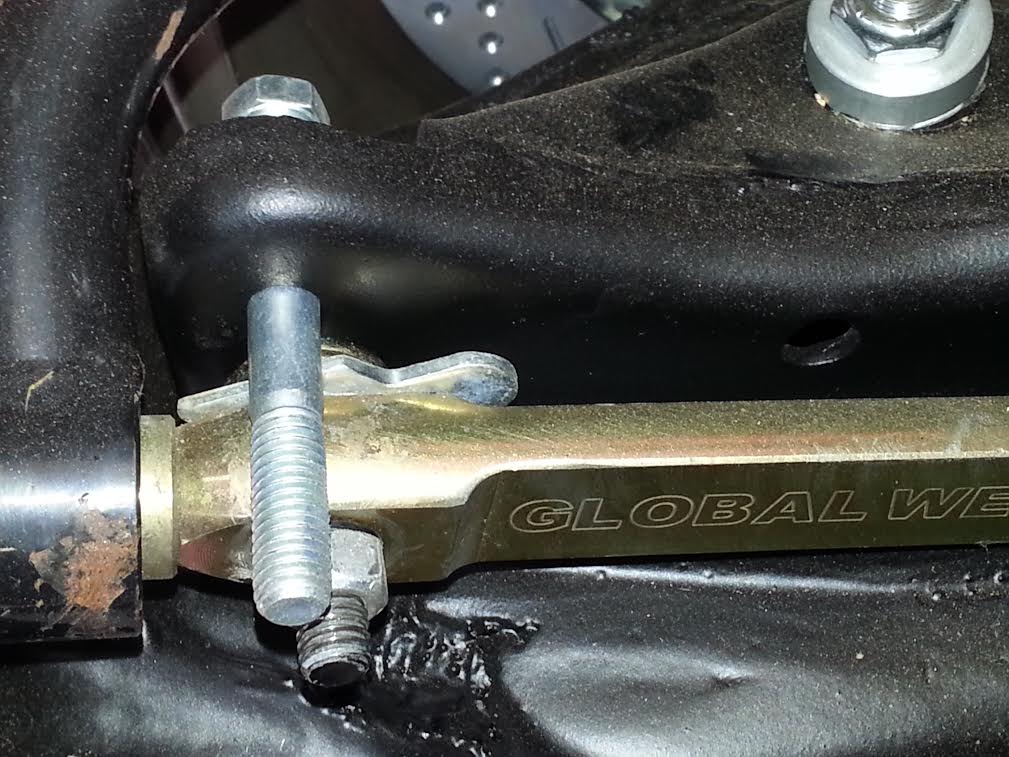
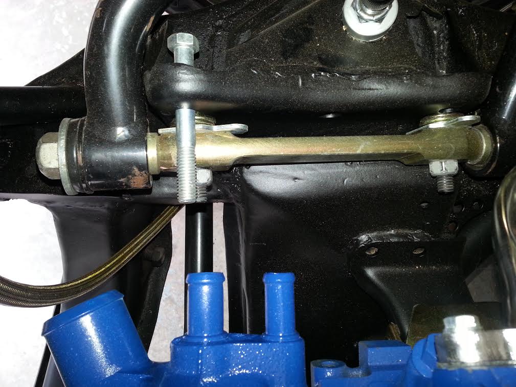
hope this helps I have 3 Camaros here and here is the mod and how much it moves rearward, I placed a bolt in the stock location for comparison and the car is at ride height, stock location vs Guldstrand
02-01-2017 #14 -Moderator-
- Join Date
- Apr 2005
- Location
- USA
- Posts
- 4,462
I did the Guldstrand mod to my '69 Camaro years ago. The holes do move back and down, and it helped the caster and camber gain a lot. One other thing is , you may have to grind some of the front frame mount off because the control arm may hit it ( depending on what arm you use )
Jeff Tate
U.S.A.
"The best thing about participating in these events is that you get to hang out with a group of intelligent like minded people who live to achieve things in their lives. You won't find a lazy, mean, or dumb bone in their bodies." Bret Voelkel, RideTech
02-01-2017 #15 -Moderator-
- Join Date
- Apr 2001
- Location
- Central CA USA
- Posts
- 6,114
My template is what Guldstrand was recommending in 1973. We have no way of telling why they changed to other specs, but my 1973 template also shows hole positions they tried that are higher and lower than what I've shown on my web page. I would go with the later template, they have sent it out to hundreds of people, so it's obviously what they were recommending at a later date than I got mine. Personally I don't think the difference between them is enough to matter. You will be lucky to drill the holes 100% accurately and who really knows how correct the factory UCA hole locations are relative to the rest of the subframe car to car.
Below is the template Guldstrand's engineer gave me. He mentioned they tried the lower holes but they weren't as good. Keep in mind tires were different back then. To get the hole drop, I measured down with a ruler, translated that to decimal, which is the notation in ink, lower left. the shaft lowering of "app.75" was noted by the engineer when he gave it to me.
New hole offset to rear is .200". If you want to run 5 to 5.5 degrees positive caster with stock factory A arms, then the holes need to be moved rearward by 7/8" to 15/16". The problem will be the bolt head in the rear position will run into the flange or you will be trying to drill a hole beyond the metal, and the factory A arms will hit the bracket in the front before you can move them that much. Most tubular arms have 3/4" to 1" rearward offset of the upper ball joint to allow 5 deg caster without any shims.
Last edited by David Pozzi; 02-03-2017 at 09:21 AM.
David Pozzi http://www.pozziracing.com67 Camaro RS that will be faster than anything Mary owns.
02-02-2017 #16
Registered User
- Join Date
- Feb 2010
- Location
- Seacoast of New Hampshire
- Posts
- 40
David, Thank you for sharing your template and history from Guldstrand for all to see. It's an impressive piece of history.....at least for us car guys
 I'll be doing the mod this weekend along with new suspension. I'm getting help from Rodney who was been very gracious with his time explaining things.....me being a relatively new person to Pro Touring.

69 x-44 in the making
2002 Camaro LE SS vert. w/lots of mods.
02-02-2017 #17
Registered User
- Join Date
- Nov 2008
- Location
- Lawrenceburg, TN
- Posts
- 4,098
Damn Dave that ones sweet!! you never showed me that one! all i have is dickeys new one
Originally Posted by David Pozzi
02-02-2017 #18 Registered User
- Join Date
- Nov 2008
- Location
- Templeton, CA
- Posts
- 561
I did the Guldstrand mod on my other subframe and thought there was talk about doing one or the other but not both, as in taller ball joints, spindles? Correct me if I'm wrong here. Just thought I would throw this out for others looking into it.
Robert
My sloooow build thread...https://www.pro-touring.com/showthre...hlight=Orngasm
"If happiness is in your destiny, you need not be in a hurry."
If I can only convince myself of this!
02-02-2017 #19
Registered User
- Join Date
- Nov 2008
- Location
- Lawrenceburg, TN
- Posts
- 4,098
the factory suspension has a positive camber gain (the wheel actually angles out at the top when compressed or turning) a tall .500 ball joint just barely gives you a neutral gain (you have neither positive or negative within a certian range) so you can run the tall ball joint (.500) and the guldstrand together ,,,,the (ridetech/Fatmans) tall spindle and standard ball joint just moves the gain into negative and that helps more than the tall ball joint, so you dont "need" to do the guldstrand with the (ridetech/Fatmans)tall spindle, but to have an aggresive gamber gain (like a C5 corvette) you can run both the ridtech/fatmans spindle and the guldstrand.............the reason i have to point out that spindle, is that some "TALL" spindles like the cpp spindles are not as tall as the ridetech/fatman spindle ....the speedtech/ATS spindle is taller than CPP and shorter than the Ridetech/Fatmans spindle, so with the Speedtech/ATS spindle to get a good curve I also used a .500 tall ball joint and it was better than the (ridetech/Fatmans) by itself and almost like the (ridetech/Fatmans) and guldstrand together.....thats just what i have tested and raced with Originally Posted by ROBS6T8
hope that helps
02-03-2017 #20
-Moderator-
- Join Date
- Apr 2001
- Location
- Central CA USA
- Posts
- 6,114
One thing that I've run into is going to a drop spindle lowers the angle of the upper A arm so camber gain is greatly reduced. Originally Posted by Rod
Stock suspension has a camber curve when plotted out. If you start out at zero camber at what I call "normal ride height" "N", then push the wheel up an inch at a time, you will have camber gain measurements. As you go up from "N" camber increases more at each step. On a stock first gen, it can go positive the first inch, then start going negative more and more each step. You can install a 1" taller upper ball joint and the camber will increase more rapidly, a good thing. You can then install a 1" tall lower ball joint and this would lower the front 1", so you need to raise it back up to "N" height by shimming the springs. NOW your 1" taller upper ball joint is at a height that a stock upper ball joint would be. This change places the upper control arm at a flatter angle and there will be less camber gain, closer to what a stock camaro would be. There is a little benefit from the tall lower ball joint, but it is in roll center geometry, almost no help in camber gain. So in a 2" drop spindle, you have to make the top of the spindle at least 2" taller to keep the upper control arm at the angle it would have been stock. And, we know the stock UCA angle is not that great for generating negative camber. The drop of the spindle takes away upper A arm angle.
Any camber gain charts you see need to be starting at the same ride height or they will be difficult to compare.Last edited by David Pozzi; 02-03-2017 at 10:00 AM.
David Pozzi http://www.pozziracing.com67 Camaro RS that will be faster than anything Mary owns.


 Reply With Quote