


Results 21 to 31 of 31
Thread: Guldstrand Mod Templates
-
02-03-2017 #21

 Registered User
- Join Date
- Nov 2008
- Location
- Lawrenceburg, TN
- Posts
- 4,098
 I will do that in the morning, I will do it both on Plain Jane and Suzys car...and post a picture....ugly betty hasnt had the mod done, waiting on products to show the full Ugly Betty build
 Originally Posted by David Pozzi

-
02-03-2017 #22
 -Moderator-
- Join Date
- Apr 2001
- Location
- Central CA USA
- Posts
- 6,114
One thing that I've run into is going to a drop spindle lowers the angle of the upper A arm so camber gain is greatly reduced. Originally Posted by Rod
Stock suspension has a camber curve when plotted out. If you start out at zero camber at what I call "normal ride height" "N", then push the wheel up an inch at a time, you will have camber gain measurements. As you go up from "N" camber increases more at each step. On a stock first gen, it can go positive the first inch, then start going negative more and more each step. You can install a 1" taller upper ball joint and the camber will increase more rapidly, a good thing. You can then install a 1" tall lower ball joint and this would lower the front 1", so you need to raise it back up to "N" height by shimming the springs. NOW your 1" taller upper ball joint is at a height that a stock upper ball joint would be. This change places the upper control arm at a flatter angle and there will be less camber gain, closer to what a stock camaro would be. There is a little benefit from the tall lower ball joint, but it is in roll center geometry, almost no help in camber gain. So in a 2" drop spindle, you have to make the top of the spindle at least 2" taller to keep the upper control arm at the angle it would have been stock. And, we know the stock UCA angle is not that great for generating negative camber. The drop of the spindle takes away upper A arm angle.
Any camber gain charts you see need to be starting at the same ride height or they will be difficult to compare.Last edited by David Pozzi; 02-03-2017 at 10:00 AM.
David Pozzi http://www.pozziracing.com67 Camaro RS that will be faster than anything Mary owns.
-
02-03-2017 #23
Registered User
- Join Date
- Nov 2008
- Location
- Lawrenceburg, TN
- Posts
- 4,098
well said...how do you explain it better then me Originally Posted by David Pozzi
I just ask myself "What would Mary say?"Last edited by David Pozzi; 02-03-2017 at 05:20 PM.
02-03-2017 #24
Registered User
- Join Date
- Feb 2010
- Location
- Seacoast of New Hampshire
- Posts
- 40
David, What numbers are you suggesting for the front bolt hole down....1.060 or .875? In a previous post you said to use the later template....Is it yours on your web site, Rodney's or somewhere else??? I'm going to do the mod this weekend and would like to do it right.
Below is from your website:
My measurements off my template are lower ft bolt 1.060" lower rear bolt .775" To measure, draw a line through the top hole centers, the cross hairs are accurate reference points, the circles are a bit off center so don't use them. Measure down from this line. The lower holes are also offset 1/4" to the rear to increase positive caster adjustment. My template was aquired by me when I visited Guldstrand sometime arond 1973, I talked to an engineer there who said they developed this template for Penske. My version shows some alternate holes that were tried, these holes were higher and lower than this "final" version.
NOTE Chicane67 was an employee of Guldstrand Ent and says his hole lowering measurements are: F .875" R .775"
69 x-44 in the making
2002 Camaro LE SS vert. w/lots of mods.
02-03-2017 #25
-Moderator-
- Join Date
- Apr 2001
- Location
- Central CA USA
- Posts
- 6,114
.875"F & .775"R & .200 rearward. Which Chicane 67 recommended is the most reliable source. He worked there when he got it. It isn't that different from mine, so you could use either one and not notice the difference in my opinion. The yellow sheet seems to say .75" drop, which is less, and I think the Guldstrand mod is already a little conservative, so it doesn't seem as attractive to me. You could easily use the Guldstrand mod with a .5" tall upper ball joint and stock lower BJ - stock height spindle. That is how conservative the drop is. Originally Posted by dondb
Last edited by David Pozzi; 02-03-2017 at 05:41 PM.
David Pozzi http://www.pozziracing.com67 Camaro RS that will be faster than anything Mary owns.
02-03-2017 #26
Registered User
- Join Date
- Feb 2010
- Location
- Seacoast of New Hampshire
- Posts
- 40
Thank you David. I currently have the level 2 Hotchkis TVS system on my car. I am going to do the G Mod, and install the hybrid Viking front double adjustable coilovers, and the Tru Turn system. For now i'm going to leave the Hotchkis rear leafs and put in the viking smooth shocks to match the front shocks. I'm going this route because the front was about 1/4 to 1/2 inch different between the driver and passenger side.....not to mention the car rides like a buck board. I appreciate your clarification on the measurements!
69 x-44 in the making
2002 Camaro LE SS vert. w/lots of mods.
02-12-2017 #27
Registered User
- Join Date
- Nov 2008
- Location
- Lawrenceburg, TN
- Posts
- 4,098
Originally Posted by David Pozzi
placing it on the cross cross-shaft
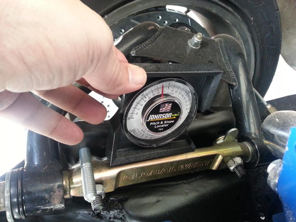
angle finder on the cross shaft
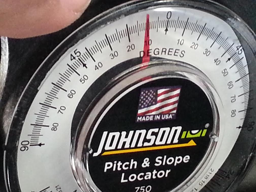
02-17-2017 #28
Registered User
- Join Date
- Jan 2014
- Posts
- 119
I'm about to finally pull the trigger on this...
Will I be using stock alignment specs?
*Also... I am now currently using CPP C5 spindles... which, according to my measurements are 1" taller than stock... so will probably end up with stock height ball joints.
05-30-2017 #29
Registered User
- Join Date
- Apr 2017
- Posts
- 9
Anyone got a true to scale template I could get. Emailed guldstrand motorsports 3 weeks ago and still have not gotten a response
05-31-2017 #30
-Moderator-
- Join Date
- Apr 2001
- Location
- Central CA USA
- Posts
- 6,114
Best bet is to draw your own. Mine is a photo copy, if I copied it and sent it to you, it would be a copy of a copy and not very useful.
What I did was take my copy and verify the hole spacing between the A arm hole centers. If that's a little off, the bolts won't go through correctly.
Also in drilling the holes, start small and work up. Center punch the holes well and get the drill lined up straight so it doesn't wander. A 7/16" drill bit is .4375" but they often drill .003" oversize.David Pozzi http://www.pozziracing.com67 Camaro RS that will be faster than anything Mary owns.
07-22-2026 #31
Registered User
- Join Date
- Aug 2007
- Location
- Albemarle, NC
- Posts
- 1,171
Necrobump!!!
Is this applicable to both forst and second gen f bodies? I believe it os, but want to make certain before applying it to my 80 firebird build.Michael Crawford
1970 plymouth Duster back under construction:
https://www.pro-touring.com/showthre...uring-makeover
1987 GMC S15 https://www.pro-touring.com/showthre...ct-drivabeater

 Reply With Quote