


Results 21 to 40 of 42
-
06-24-2016 #21

 Registered User
- Join Date
- Feb 2010
- Location
- NE Arkansas
- Posts
- 617
To hook up a electric speedometer to the ECU here are some changes that you need to make in the harness and software. I honestly don't know why Holley didn't included this already configured as part of the kit.
Harness Changes:
1. Locate the 8-PIN input / output female connector in the main harness and the supplied male connector that has 271R1096A on the bag.
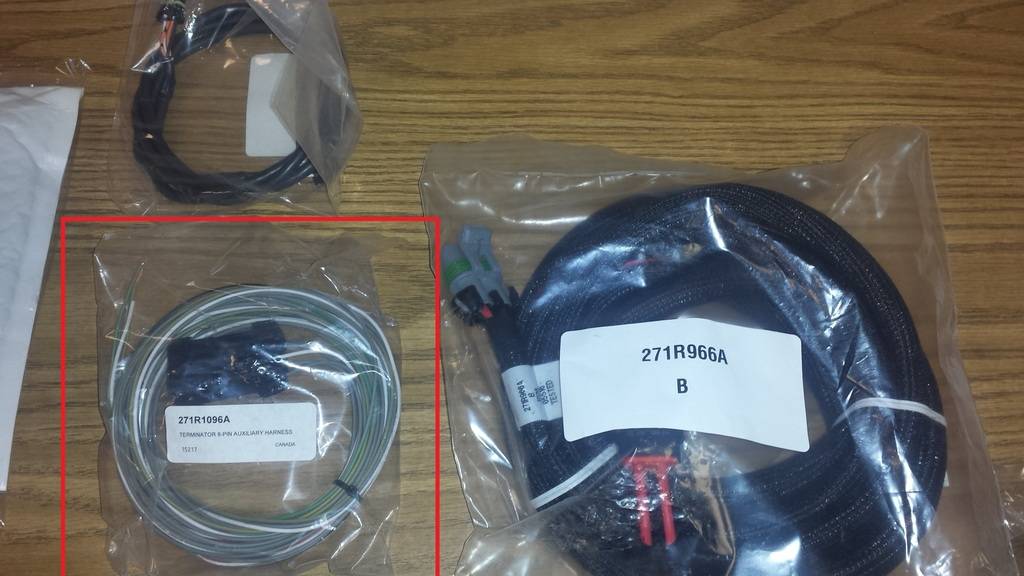
2. The male connector will already be set up like this, except for the speedometer you need to add that. The other wires should already be there.
Type Circuit Cavity Function Wire color Input A12 A Input A3 B IAC Kick White / red stripe Input A13 C Input A4 D Output B12 E AC Shutdown Gray / yellow stripe Output B11 F Speedometer Your Choice Output B10 G Fan 1 Gray / black stripe Output B3 H Fan 2 Gray/ Green stripe
Since you need to add the wire for the speedometer, you also need a terminal to crimp the wire to snap into that connector. Good thing you only need the male side of the connector. The wiring and terminals for the harness side are all in place and routed to the correct spot on the ECU.
You just need to locate some Delphi Metri-Pack 150 Series male terminals. You can get them on eBay for the best price.
Here's more information on the terminals and plugs needed if your need more input/outputs and don't want to buy holleys harness
http://forums.holley.com/showthread....als-Holley-EFI
Once you have the wire and terminal installed in the correct cavity and routed to the speedometer where it needs the input signal it's on to the programming part of this set up.
Software Changes:
There are a few areas in the software you have to make changes for the ECU to output a speed signal for the speedometer. Keep in mind there isn't anything loaded on the ECU at this point so you will either need to use the hand held to set basic parameters or use a laptop, set up your software and load on the ECU. I didn't even mess with the handheld and used the laptop for everything.
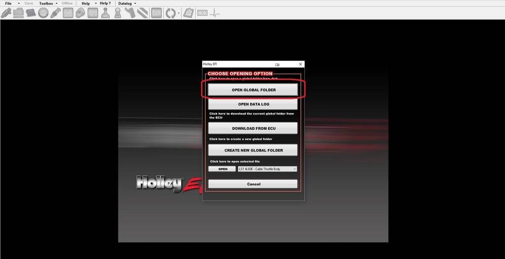
1. Start the software and choose Open Global Folder
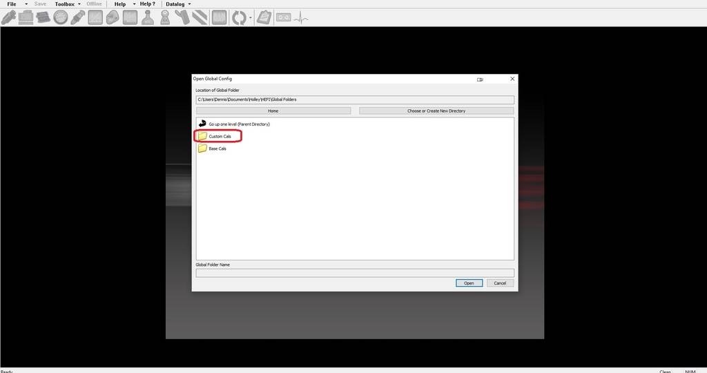
2. Choose custom Cals
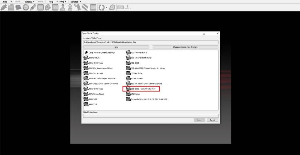
3. In my case I chose LS1 4L60e cable Throttle Body
4. First you will need to set the transmission parameters to make sure your speedometer gets the correct signal. Click on the icon that says Transmission ICF
I have a 4L60e so these are the settings I changed:
- Transmission Type
- Tire Diameter
- Rear Gear Ratio
- Check Speedometer Output enable box and put the desired number of pulse per mile you need. I put 4000 PPM because that's what GM uses, if your speedometer is aftermarket it won't matter as long as you get it in the ranges it needs. My VHX speedometer accepts 4000-128,000 PPM.
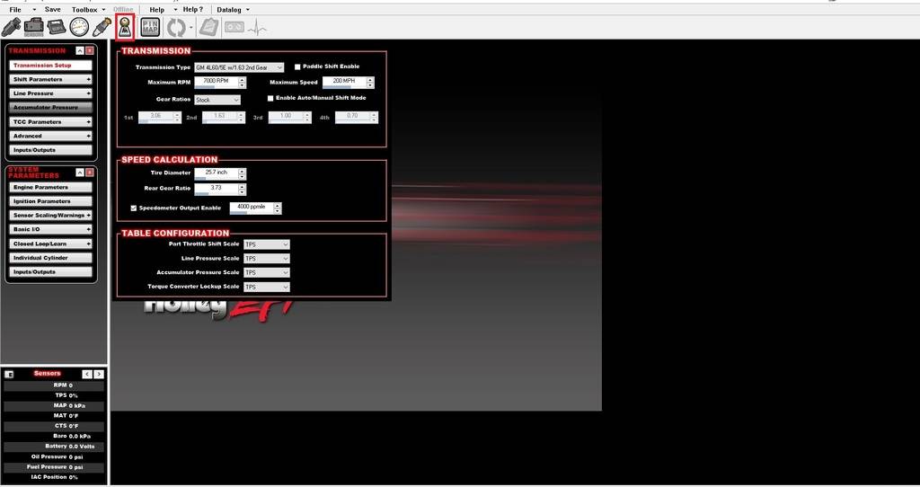
5. Once you set the transmission paremeters, click on the PIN MAP ICF and drag the speedo unassigned output to B11 as pictured
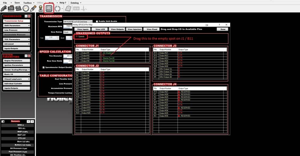
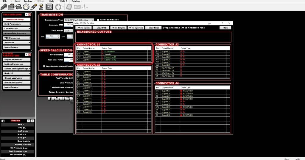
6. And thats it! This is the way it should look. Make your other changes for your engine (engine size, injectors etc) and upload to your ECU.
I will also note, on the base calibration that I used, the fan1 and fan2 ouputs weren't in the correct location on the software pin outs. I had to move them to B10 (output #3) and B3 (output #4) as you see pictured here. Just make sure thats correct or your fans won't work right.
Hope that helps yaMy build thread
http://www.nastyz28.com/forum/showthread.php?t=241037
Paint Jail Experience
https://sites.google.com/site/paintjail/home
-
06-24-2016 #22
Registered User
- Join Date
- Feb 2010
- Location
- NE Arkansas
- Posts
- 617
This system isn't as "plug n play" as it's made out to be, I guess unless you have a corporate crate engine or something the handheld is useless. It's designed to allow you to plug in basic parameters to get the engine going.
Since I have the Fbody fuel rail and EV1 injectors I had to use a laptop because the hand held didn't have a choice for those style injectors, which was weird.My build thread
http://www.nastyz28.com/forum/showthread.php?t=241037
Paint Jail Experience
https://sites.google.com/site/paintjail/home
06-24-2016 #23
Registered User
- Join Date
- Feb 2010
- Location
- NE Arkansas
- Posts
- 617
And another thing I will mention, if your not going to use the AC shutdown output (Pin B12, Output #1) with your set-up you could move that to unassigned and put the Speedometer output signal there. Then you wouldn't have to crimp and install a wire on the harness plug. Just use what's already there.
My build thread
http://www.nastyz28.com/forum/showthread.php?t=241037
Paint Jail Experience
https://sites.google.com/site/paintjail/home
06-24-2016 #24
Registered User
- Join Date
- Jan 2014
- Location
- Austin, TX
- Posts
- 664

perfect thanks!! I was concerned that I would need the V4 software as I downloaded it, but it wouldn't open on my apple for some reason.
06-24-2016 #25
Registered User
- Join Date
- Feb 2010
- Location
- NE Arkansas
- Posts
- 617
No problem at all, as for software try V2 first
My build thread
http://www.nastyz28.com/forum/showthread.php?t=241037
Paint Jail Experience
https://sites.google.com/site/paintjail/home
06-24-2016 #26
Registered User
- Join Date
- Jan 2014
- Location
- Austin, TX
- Posts
- 664
good idea....thanks...thats probably what Ill do Originally Posted by 1976CamaroGuy

08-04-2016 #27
Registered User
- Join Date
- Jan 2014
- Location
- Austin, TX
- Posts
- 664
One more question for you as Im finally getting back to this after being out of town for a few weeks...the gray wire that comes from the transmission harness that unlocks the converter when the brakes are applied....its says to connect that to a +12v source on the brake switch. My brake switch has two wires...one is orange, coming from the fuse panel, and is a constant +12v source. The other wire is white, running from the switch, to the turn signal. Which of these two should the gray wire be hooked to? Im assuming the white one as I don't think its supposed to see a constant +12V, but just wanted to verify.
Thanks again for all your help with this!
08-04-2016 #28
Registered User
- Join Date
- Feb 2010
- Location
- NE Arkansas
- Posts
- 617
I can't remember the color wire on mine, but your going to want to splice the wire that only shows 12 volts when the brakes are applied at the switch. Easiest way to do this is get a test light and probe the wire that lights up when the brakes are applied and goes off when you let off the brakes. That's the wire you want and do that at the switch under the dash.
My build thread
http://www.nastyz28.com/forum/showthread.php?t=241037
Paint Jail Experience
https://sites.google.com/site/paintjail/home
08-04-2016 #29
Registered User
- Join Date
- Feb 2010
- Location
- NE Arkansas
- Posts
- 617
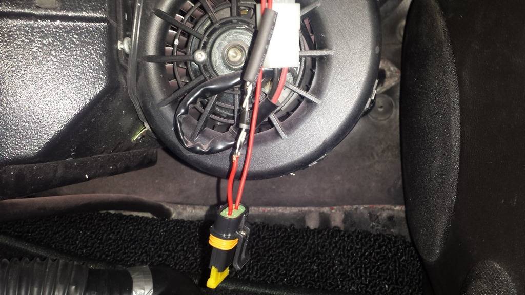
Another thing on the transmission solenoid wire, your going to need to use a relay or a blocking diode to prevent backfeed from the solenoids. If this isn't done your car will most likely not shut off after you start it...even if you pull the key out of the ignition...ask me how I know
I used a blocking diode so it gets power to the solenoids, but it doesn't let power back out that can feed back into the electrical system
 My build thread
http://www.nastyz28.com/forum/showthread.php?t=241037
Paint Jail Experience
https://sites.google.com/site/paintjail/home
08-04-2016 #30
Registered User
- Join Date
- Jan 2014
- Location
- Austin, TX
- Posts
- 664
Thats what I figured....so the gray wire goes on the output side of the switch with the white wire.
Already wired in the diode....saw your post earlier. I did specifically run the ECU and Trans to separate 12v sources....but I guess its all one big loop regardless.
08-04-2016 #31
Registered User
- Join Date
- Feb 2010
- Location
- NE Arkansas
- Posts
- 617
yeah it's the side of the switch that energizes the taillights
I ran mine to seperate fused 12v sources, but your right it's one big loop...didn't matter in my caseMy build thread
http://www.nastyz28.com/forum/showthread.php?t=241037
Paint Jail Experience
https://sites.google.com/site/paintjail/home
08-10-2016 #32
Registered User
- Join Date
- Jan 2014
- Location
- Austin, TX
- Posts
- 664
about to fire up....just wanted to verify....I used a 6 AMP, 50 volt Mouser Electronics blocking diode....I assume that will be sufficient to prevent the back-feed into the system and prevent the engine from running after the key is secured?
08-10-2016 #33
Registered User
- Join Date
- Feb 2010
- Location
- NE Arkansas
- Posts
- 617
that should fine, good luck! gonna be an awesome feeling hearing it run Originally Posted by FLYNAVY53
My build thread
http://www.nastyz28.com/forum/showthread.php?t=241037
Paint Jail Experience
https://sites.google.com/site/paintjail/home
08-10-2016 #34
Registered User
- Join Date
- Jan 2014
- Location
- Austin, TX
- Posts
- 664
So....initial fire up....following a few small fuel leaks:
1: even with the idle set screw backed all the way off, motor still idles at 1500 RPM at 200 degrees with the hot idle set at 750
2: system continues to operate in "open loop" despite the fact that it should be in "closed loop"
3: Fuel Learn Status - continues to show "NoLearn" even at 200 degrees....should switch to "Learn" above 160
Not exactly sure where to go from here...everything appears to be working properly....all sensors read correctly and the engine fires right off with no issues other than the high idle and the fact that the computer doesn't seem to be "tuning" itself as advertised in the directions.
Any help would be greatly appreciated.
Thanks,
Greg
08-11-2016 #35
Registered User
- Join Date
- Feb 2010
- Location
- NE Arkansas
- Posts
- 617
Yours is different than mine with it being throttle body injection? I'm no expert but here are some of the things I looked into when setting up mine.
1. High idle - if you can't control it or the ECU isn't tuning it properly check for vacuum leaks. That's one of the biggest culprits of high idle because basically idle is a controlled vacuum leak.
2. If it's not going into closed loop, make sure your o2 sensor is working properly. Leaks in the exhaust around that area can cause the o2 sensor to do weird things
3. Not sure on this
Another thing, is post some of your issues in the TBI section on the Holley Forums, those guys are pretty knowledgeable about these things. http://forums.holley.com/forum.php
08-11-2016 #36
Registered User
- Join Date
- Jan 2014
- Location
- Austin, TX
- Posts
- 664
So essentially, Im an idiot....which I suppose is better than actually having a problem. When I disconnected the trans solenoid wire the other day to splice in the diode, not only did I install the diode backward, but neglected to reconnect the wire. Apparently having that disconnected adversely affected something in the ECU, because as soon as I reconnected it, the truck lit right off and the idle worked its way down to 950 RPM with the ECU running in closed loop as it should. Of course, when I went to shut it down, it kept running because the diode was oriented wrong....but after correcting that, all is well.
Tomorrow Ill get the tank back in the truck (I had it on the ground in the event I had any fuel leaks that needed addressing) and Ill be able to back it out into the driveway and let it get up to full operating temp and then take it for a drive....too many fumes in the garage to let it sit idling for 15 minutes.
Thanks again for all the help with this process....hopefully Im pretty close to being back on the road.
08-12-2016 #37
Registered User
- Join Date
- Feb 2010
- Location
- NE Arkansas
- Posts
- 617
Awesome man, Glad you figured it out. That's the main part.
It still aggravates me that Holley couldn't have built something as simple as a blocking diode into the solenoid power side instead of leaving it up to the customers to do it.My build thread
http://www.nastyz28.com/forum/showthread.php?t=241037
Paint Jail Experience
https://sites.google.com/site/paintjail/home
08-13-2016 #38
Registered User
- Join Date
- Jan 2014
- Location
- Austin, TX
- Posts
- 664
Agreed! That and the fact that theres no output for things like a speedometer. Seems like a really nice set up for a street car thats just missing a few things...
08-13-2016 #39 -Moderator/Sponsor-
- Join Date
- Apr 2001
- Location
- The City of Fountains
- Posts
- 16,120
Those things aren't missing, they just are not preconfigured. Think about the various possible combinations that people run. How can Holley possibly accommodate them all, except by offering a super flexible system that can be user defined to their needs? Originally Posted by FLYNAVY53
Y'all should also look into running your fans in pwm mode instead of discrete.
Andrew1970 GTO Version 3.0
1967 Cougar build
GM High-Tech Performance feature
My YouTube Channel Please Subscribe!
Instagram @dr__efi
I deliver what EFI promises.
Remote Holley EFI tuning.
Please get in touch if I can be of service.
"You were the gun, your voice was the trigger, your bravery was the barrel, your eyes were the bullets." ~ Her
08-13-2016 #40
Registered User
- Join Date
- Feb 2010
- Location
- NE Arkansas
- Posts
- 617
I've thought about that, right now my fan is wired into a three way set-up like a 4th gen camaro. So they both run low speed most of the time with Fan 1 trigger, and high speed when it hits the Fan 2 trigger. Either way this is def quieter than the way I had it with my old PCM and two relay set up.
My build thread
http://www.nastyz28.com/forum/showthread.php?t=241037
Paint Jail Experience
https://sites.google.com/site/paintjail/home


 Reply With Quote


