


Results 1 to 20 of 25
-
03-13-2011 #1

 Registered User
- Join Date
- Nov 2010
- Location
- Ventura County CA
- Posts
- 556

Guldstrand mod the "hard way"
With things down to the frame on my '70 Nova, I decided now would be a good time to address some of the suspension shortcomings that I was fighting at autocross last year. First, it's well documented that the camber curve for 1st gen Camaros and 3rd gen Novas like mine is a bit backwards. There are a host of ways to address this and I decided to do the rather popular Guldstrand mod. As you may know, this moves the upper control arm frame mounting points down a bit to primarily increase negative camber on compression ("camber gain"). If you want to learn more about this, do some searching because it's been discussed in detail elsewhere.
The conventional method for implementing the G-mod is to drill a second set of holes lower on the UCA towers. I've decided instead to do the G-mod the "hard way" by cutting the UCA towers off at their base and welding them in at the new location. I am not the first to do it this way, but information and pictures have been hard to find, so I decided to document the process to help others.
I started by pulling apart the suspension. I supported the weight of the car with a jack near the balljoint on the lower control arm, then loosened the upper balljoint, used a seperator to get it to "pop" while the nut was still on the end, then simply loosened the nut until it came loose. There was a little bit of spring energy left when the nut came off, but not much - the car moved up only a little bit. Now I realize this is not safe to do on all vehicles, but in this case it worked out fine. I had left the shock in place just in case things decided to go flying anywhere. Finally I put a jackstand under the front of the frame and lowered the jack to release the spring.
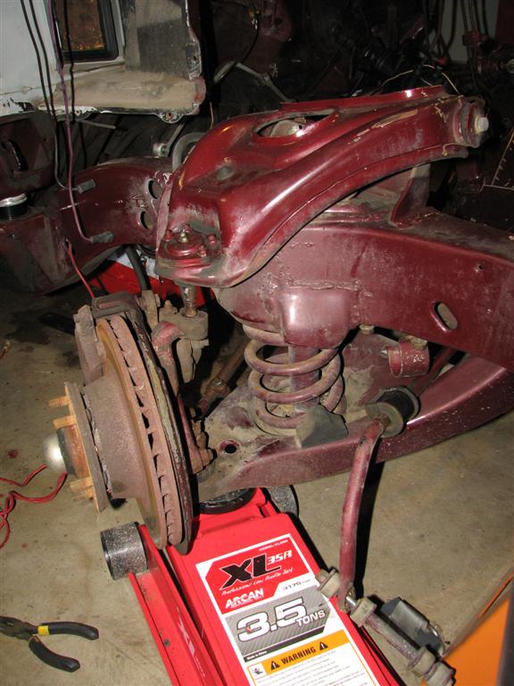
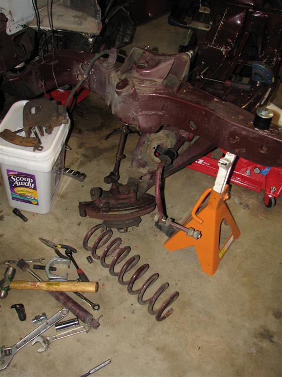
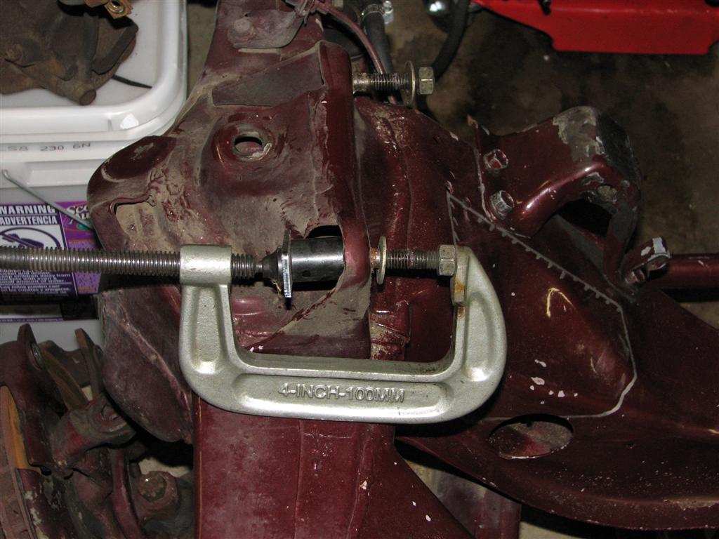
First I used a c-clamp and a socket to remove the studs for the upper control arms.
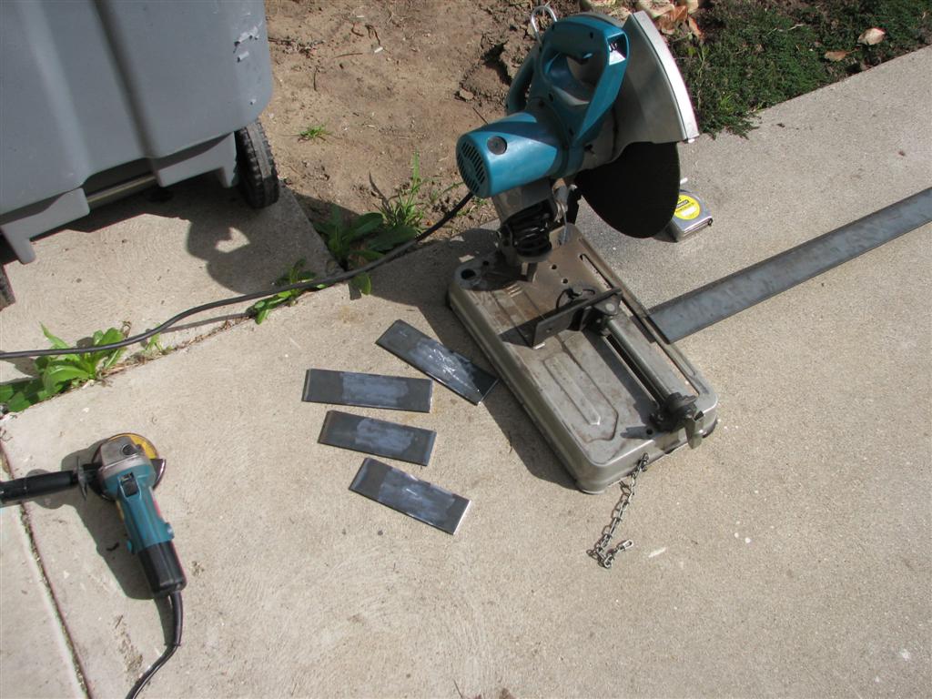
I then cut a few pieces from 2-1/2 x 1/8 bar
I bought the actual template directly from **** Guldstrand's shop. You can download copies of it off the net, but I like to support the people that develop these things and this way I was assured I had the right dimensions. Here I use a punch to transfer the hole locations to a piece of flat.
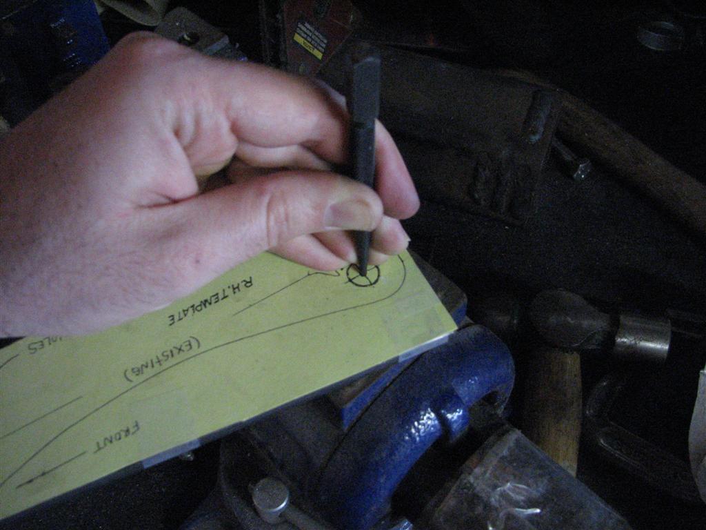
After drilling the four 7/16" holes, I trimmed the lower portion of the plate to follow the flat contoured section of the UCA tower. The new location for the lower hole is very close to a curved potion of the tower, so I ground it at an angle on the backside so the plate would sit flat.
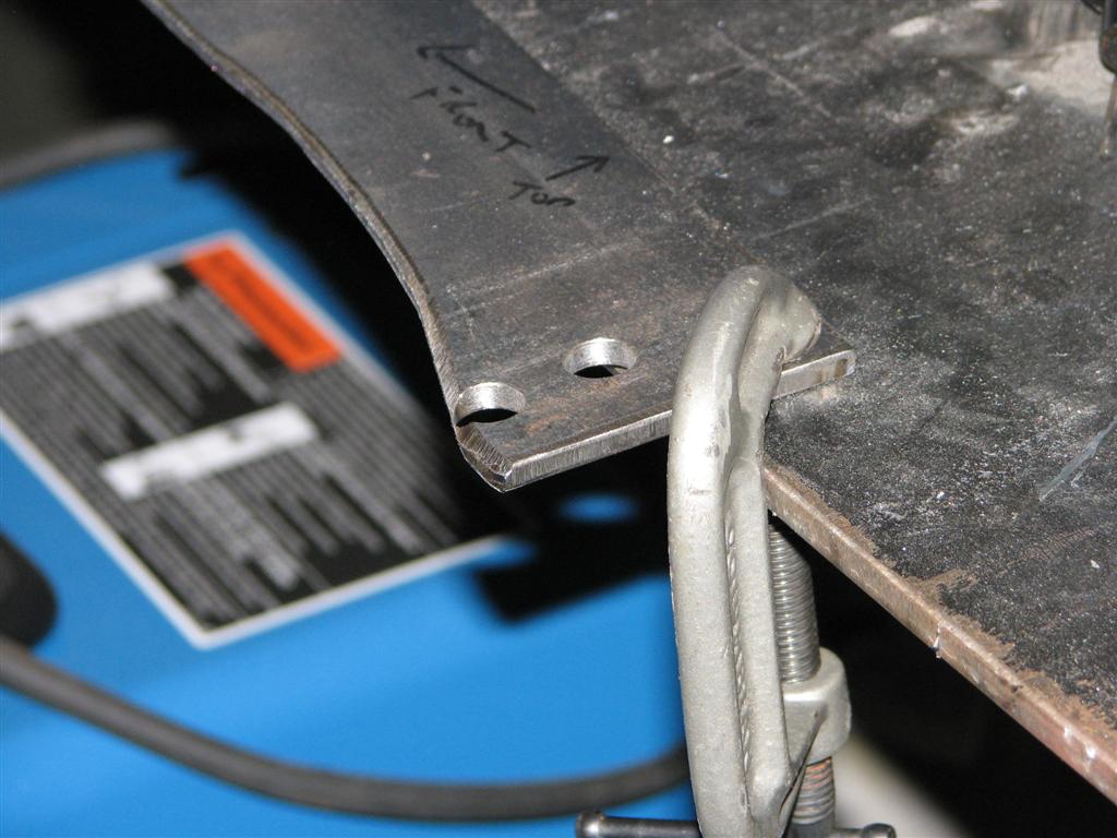
Here is the relocation plate now bolted on both sides
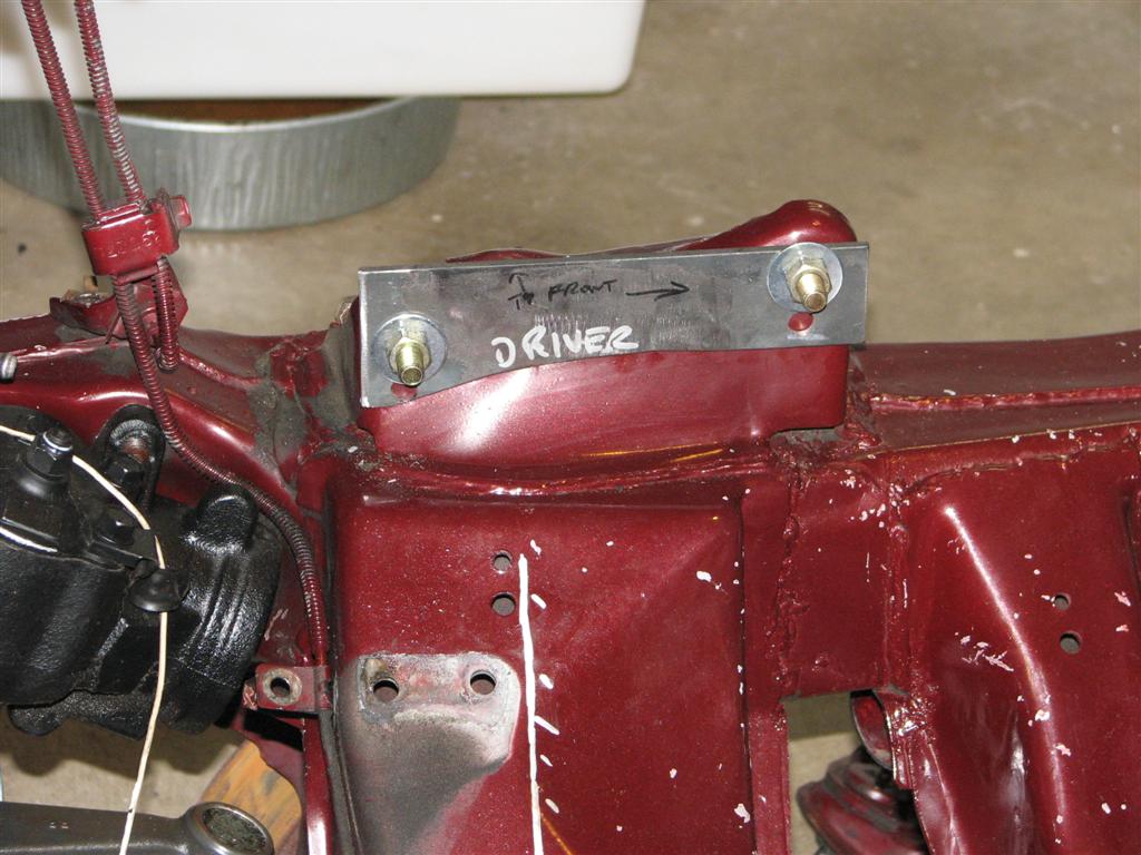
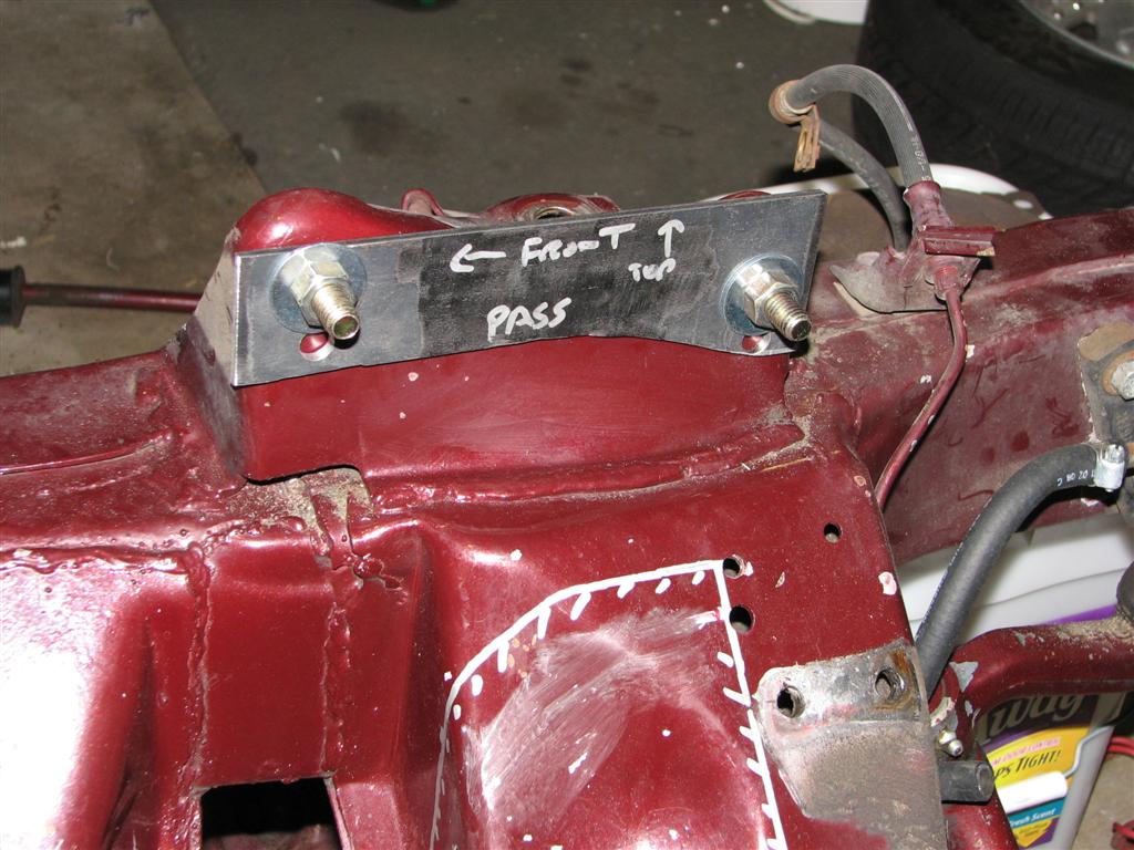
Next I made plates that bolt to the motor frame stand locations.
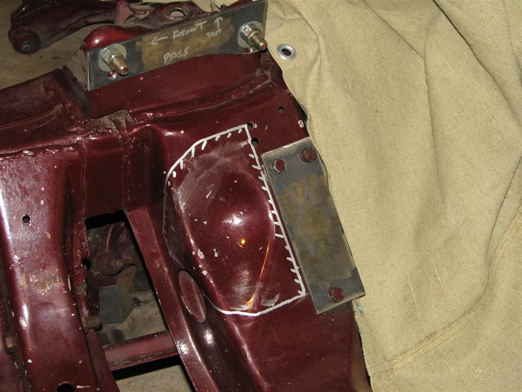
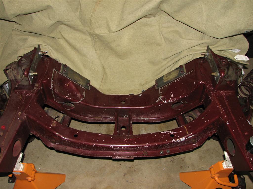
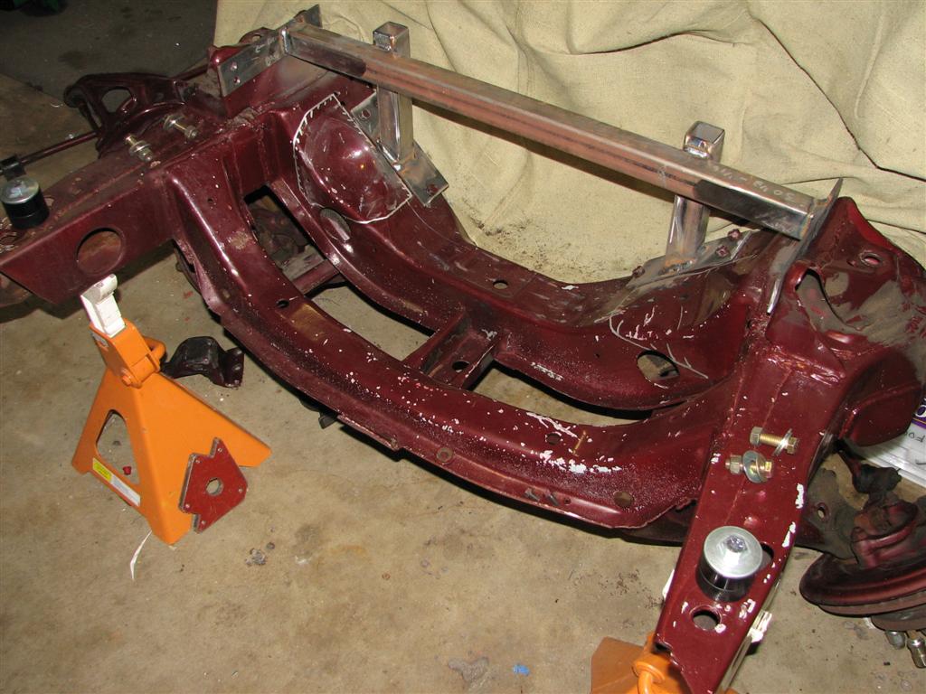
Then I cut a crossbar from 1.5x.120 square tube that I had laying around and two downtubes with 45s at the end to support it. I welded everything up and here's what I have:
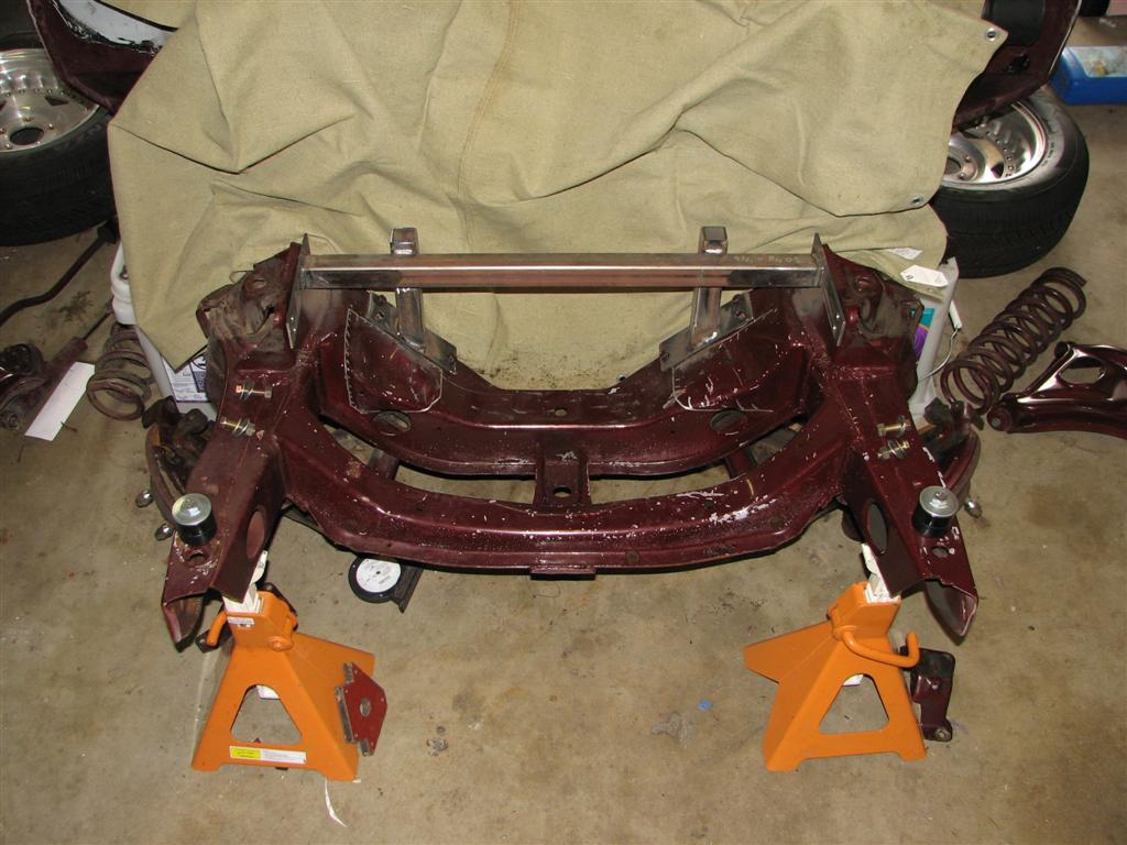
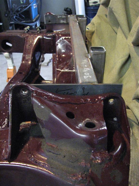
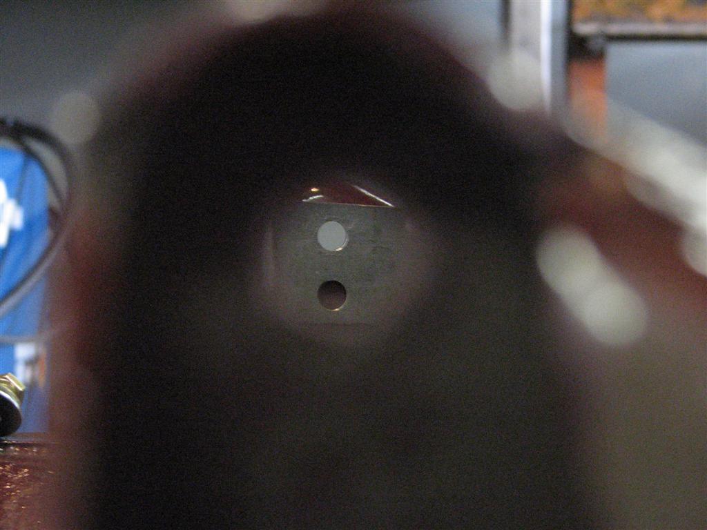
I considered adding more tube to ensure things lined up, but after thinking about it I figured more tube would just be more welding and more possibility for distortion. This simple design was easy to build and the holes lined up just fine after removing the bolts (proof!)
Next I'll have to cut the towers off and carefully trim them until they can mate up with the lower holes on the jig. That's all for now!Clint - '70 Nova "restomod" cruiser & autocross family car

-
03-14-2011 #2
 Registered User
- Join Date
- Feb 2010
- Location
- ARIZONA
- Posts
- 139
Very Nice! Your jig looks great. This is exactly how I was going to do it on my '67 Camaro. I even did a CAD drawing of the "template" and laser cut them at work. I did a cad model and I think raising the upper ball joint gives a little better geometry so that is the way I am going now. However, the G Mod is very close and has proven to be a big improvement.
Keep the pics coming.Larry
67 Camaro, 350 SB, Custom A-Arms & 3-Link
My Build https://www.pro-touring.com/showthre...LOVE-67-Camaro
-
03-14-2011 #3
 Registered User
- Join Date
- Apr 2004
- Location
- Cedar Rapids, IA
- Posts
- 999
I'm interested as well. Looks good so far.
Some times I'm fast sometimes I'm half-fast
-
03-14-2011 #4
 Registered User
- Join Date
- Jul 2010
- Location
- Monticello, MN
- Posts
- 249
Probably the best of the jig ideas I have seen. It looks simple and sturdy, two very effective design qualities in my opinion.
What do you have planned for the two radiused areas you have marked up on the crossmember near the motor mount plates?
-
03-14-2011 #5
 Registered User
- Join Date
- Aug 2004
- Location
- Ontario, Canada
- Posts
- 2,314
 I'll take a wild assed guess and say he is making room for some LS accessories.
 Originally Posted by Roberts68

KenIf there is a hard way to do something, I'll find it!
My other car is a Vega.
-
03-15-2011 #6
Registered User
- Join Date
- Nov 2010
- Location
- Ventura County CA
- Posts
- 556
Thanks all for the comments.
Last night I unbolted the motor mount plates and observed a definite movement of the UCA hole locations. So I removed the jig and then reinstalled it by just bolting it at the motor mounts (no bolts at the UCA towers). Doing this, the UCA hole locations fell right back into place. There is definitely some stress left in the jig from welding, but having it bolted down at the motor mounts puts it in the correct position. I think I am good to go - what do you think?
EDIT 3/17 - The jig does slip into place without force or binding. I revisited this last night and found that just putting the bolts in the motor mount holes without tightening them gets the UCA holes lined up within 1/8". Pushing down on the motor mount plates with my fingers gets it to line up perfectly and tightening the bolts does the same. With the jig out, I put a straight edge on two adjacent sides of each box tube and they were not bowed.
I would like to retract my statement about there being significant springback due to welding - I think this jig in good shape.
Roberts68, I have those areas marked out for the AC compressor and alternator for my LY6. I'm thinking about starting a thread somplace here, but my car doesn't really fit the Pro-Touring mold. Here is a thread on LS1tech documenting my swap: http://www.ls1tech.com/forums/conver...00-6-0vvt.htmlClint - '70 Nova "restomod" cruiser & autocross family car
-
03-15-2011 #7
 Registered User
- Join Date
- Jun 2007
- Location
- Simi Valley, CA U.S.A.
- Posts
- 209
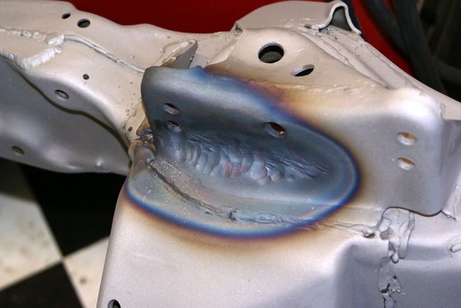
Keep in mind that most of the time you need to clearance the new location for the crossbar on the A-arm. It doesn't have to be pretty as you'll never see it but it does need to allow the now lowered Cross bar to sit "flat". This picture was immediatly after the torch before I cleaned it up and made it sanitary.
-
03-15-2011 #8
Registered User
- Join Date
- Nov 2010
- Location
- Ventura County CA
- Posts
- 556
Lance, that shouldn't be necessary for me since I'm cutting the tower at it's base and moving the whole thing down. The lack of a flat mounting surface when simply drilling the holes is one of the reasons I'm doing it this way.
I see you're from Simi - very local. What are the specs on your suspension? Would you be willing to give me a ride some time? I drive through Simi every day. I'm having a hard time deciding on springrate & shocks because I'm not sure how much stiffness I can tolerate from a ride comfort standpoint.Clint - '70 Nova "restomod" cruiser & autocross family car
-
03-15-2011 #9
Registered User
- Join Date
- Jan 2010
- Location
- Elk River, MN
- Posts
- 676
Looks great so far, nice to see ingenuity in things like the jig you've built.
-mattMatt Peterson 84 Monte Carlo - Sold :( | 99 Corvette Racecar | 2001 Z06 Daily Driver
https://www.pro-touring.com/showthre...ng-Bertha-Back
http://ls1tech.com/forums/conversions-hybrids/1499192-84-monte-5-3-build.html
https://www.pro-touring.com/threads/...rvette-Racecar
-
03-15-2011 #10
 Registered User
- Join Date
- Nov 2008
- Location
- So. Cal.
- Posts
- 1,240
Hey Clint. First off. Great work on showing the process. Lots of pics and a succinct description (I have to work on that).
You fabrication skills are right on.
I dont think the spring back is an issue. .120" wall thickness for the bar is ok. I tend to go a lil large when the distance is large (I might have used .250" wall tube), but thats not a major reach. If the mounting holes mount up with NO real force needed when bolting it back down to the motor mount plates then it ok.
But if you cant set the jig down on the motor mount plates and still clear the upper control arm mounts without bolting the jig down. Or if there is a gap on the upper control arm mounts when the jig is just set in place I see that there might be a problem.
The way I see it (I may be wrong) is the jig should be able to be unbolted all the way and just sit there. And it should be able to be removed simply and placed right back in place without ANY binding or interference, like it can be just set in place and the holes will line up.
If not when you go to cut the upper mounts the additional force needed to bolt the jig in place will shift the mounts when you cut them off from the frame. And they may shift out, in, up or down or even twist. Then you dont really know where its supposed to be after you make the cuts. So Id like to see the jig slip right in and out, no bolting before any cutting happens. Just a thought.
And we are neighbors also. I live in camdammarillo. So really, you have some support around. And I have some tools, not much knowledge. But its cool to have some local car folks right.
Oh, Id put a straight edge across the top of the cross bar to see if it bowed. I wouldnt think it would, but that would be a simple check to see if its not straight anymore and that would account for some interference or tension in the entire jig.
Gimme a shout if you want any help. I might be able to give some. JRWhat I write is opinion, none of it is factual. 2010
Even though I'm conscious it doesn't mean I'm coherent. 2011
I'm getting better with age. Best thing about old age is I don't know any better. 2012
-
03-16-2011 #11
 Registered User
- Join Date
- Aug 2007
- Location
- Vancouver, BC
- Posts
- 125
I've been curious but never got around to asking... is there any specific reason that you're choosing the harder route versus just redrilling? Just for the hell of it?
1972 Nova, forged LQ4 with twin 6466's, T56 Magnum, OEM subframe w/ Speedtech front, Chassisworks gLink rear, Ridetech coils & Wilwoods, with a rear floater in the works --> http://www.ls1tech.com/forums/conver...1972-nova.html
-
03-16-2011 #12
Registered User
- Join Date
- Jan 2010
- Location
- Elk River, MN
- Posts
- 676
Not meaning to answer for him, but he said this: Originally Posted by frojoe
-mattThe lack of a flat mounting surface when simply drilling the holes is one of the reasons I'm doing it this way.Matt Peterson 84 Monte Carlo - Sold :( | 99 Corvette Racecar | 2001 Z06 Daily Driver
https://www.pro-touring.com/showthre...ng-Bertha-Back
http://ls1tech.com/forums/conversions-hybrids/1499192-84-monte-5-3-build.html
https://www.pro-touring.com/threads/...rvette-Racecar
03-16-2011 #13 Registered User
- Join Date
- Dec 2004
- Posts
- 441
I did the same mod. Another reason is that when re-drilling the holes, you'll likely need to cut off the "ears" from the mount to allow for control arm movement without binding. I thought this method looked more sanitary. Originally Posted by frojoe
Clint, if you haven't gotten there yet, the shock mount wasn't too hatefull either.
03-16-2011 #14 Registered User
- Join Date
- Sep 2004
- Posts
- 159
Nice idea. You could probably make a buck or two renting your jig out.
03-16-2011 #15
Registered User
- Join Date
- Jul 2010
- Location
- Monticello, MN
- Posts
- 249
That's possible but I keep reading that not all these cars are the same, or no two are exactly alike so a jig from one may not fit the next and so on. Originally Posted by KQM052
It's really a pretty simple setup and I suppose it could be made to be modular and adjustable for shipping etc.
Perhaps weld some T-rod couplings in a few places and use some heavy 1/2", 5/8" or better T-rod for spanning and I bet it would work the same way and it would allow it to be used for other F/X body cars with a range of adjustment. Just back up all your adjustment points with jam nuts.
The jig made to fit and welded solid, then checked for tension and warpage is definitely the way to go though. Anybody that can't tackle making the jig ought not be welding their A-arm towers to the subframe anyway.
03-17-2011 #16
Registered User
- Join Date
- Nov 2010
- Location
- Ventura County CA
- Posts
- 556
Thanks all for the comments and feedback. It is helpful to get your input.
J - Thank you for the detailed and thoughtful response. All very good tips. It's great to know you are local - I'd love to check out your Nova and your shop some time. Originally Posted by JRouche
The jig does slip into place without force or binding. I revisited this last night and found that just putting the bolts in the motor mount holes without tightening them gets the UCA holes lined up within 1/8". Pushing down on the motor mount plates with my fingers gets it to line up perfectly and tightening the bolts does the same. With the jig out, I put a straight edge on two adjacent sides of each box tube and they were not bowed.
I would like to retract my statement about there being significant springback due to welding - I think this jig in good shape.
Honestly "for the hell of it" is a factor. You probably know from reading my LSx swap thread that I like to try things out that aren't necessarily the easiest route. For me a huge portion of the fun is the actual build and the challenge of doing things a little different. That said, I am certainly not the first to do it this way. If you search around the net, you can find other examples of jigs used in a very similar fashion for 1st gen Camaros & 3rd gen Novas. Originally Posted by frojoe
Some advantages I see to doing it this way:
- Flat surfaces for the alignment shims and cross shaft to seat against
- New hole locations may be more accurate; I suspect lining up the paper templates to the original holes, and punching and drillling from the backside of the UCA tower would be less reproducable than transfering the paper template directly to a metal locating plate on a bench the way I did it.
- Factory appearance when complete
- Gives me something to do with all my spare time (and there's so much of that!)
Some disadvantages:
- With aftermarket UCAs, the redrill method would allow you to retain the stock hole locations; this method does not, but neither would redrilling if you were using stock UCAs
- More work and materials (for the jig) are needed; I happened to have what I needed.
- Requires the engine to be out and more access; definitely a consideration if your car is already assembled.
What do you mean "hatefull"? My plan for the shock mount is to cut it off at the tower before lowering the tower, then reconnect it somehow (add metal, bend, or TBD) without changing its location. Originally Posted by bretcopsey
I can't speak from personal experience nor do I know exactly what the original manufacturing method is, but consider that DSE provides a very similar jig for installing their coilover conversion. It bolts to the two upper motor mount holes on the frame and locates UCA towers of their own design. Take a look here: http://www.lateral-g.net/tech_articl...lover_install/ Originally Posted by Roberts68
The use only the two upper holes for each motor mount location whereas I added the third hole in my design. I'm not sure how reproduceable this is with their jig, but based on what I've read about DSE, I would think it would have to be pretty good.
I agree with this. I'll also add, however that even people with the skill to do it may not have the time, so having a jig ready-made would be an advantage. If someone local wanted to use it, I'd be happy to loan it out or sell it when I'm done. Originally Posted by Roberts68
Clint - '70 Nova "restomod" cruiser & autocross family car
03-17-2011 #17
Registered User
- Join Date
- Nov 2008
- Location
- So. Cal.
- Posts
- 1,240
Yup, I have a feeling you will be a great source of help for me and Id love to have you out. The long drive will be a killer, pack some food and drinks Originally Posted by TheBandit
 And really, Im just in my three car garage, not much of a shop. Between the lathes and milling machines the car just fits. It will be a one man tour, Ill send the GPS in with you so the rescue team can find you, the place is a disaster zone. Ive already applied for FEMA help but they said self imposed disasters arent their game. WHAT!! It looks like a tornado hit, WTF? No help from them. My wife had an easy fix though. The large "EVERYTHING FOR FREE" sign got burnt up though, prolly vandals Im sure. Bad neighborhood, they would burn concrete if they could.
Ill get in contact with you so we can hook up. When you come by Ill prep you on all the disaster equipment you will need to traverse the "shop". JRWhat I write is opinion, none of it is factual. 2010
Even though I'm conscious it doesn't mean I'm coherent. 2011
I'm getting better with age. Best thing about old age is I don't know any better. 2012
04-17-2011 #18
Registered User
- Join Date
- Nov 2010
- Location
- Ventura County CA
- Posts
- 556
Work continues on the Guldstrand mod. The next step was marking where to cut.
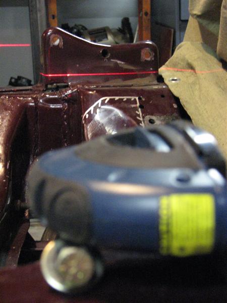
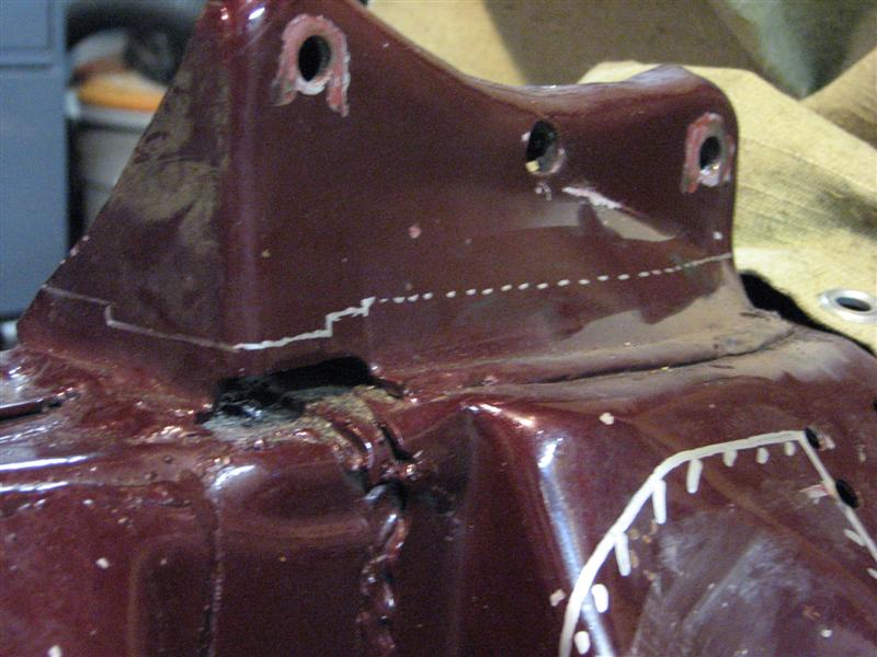
Then I used the angle grinder and cutoff wheel to cut off the tower.
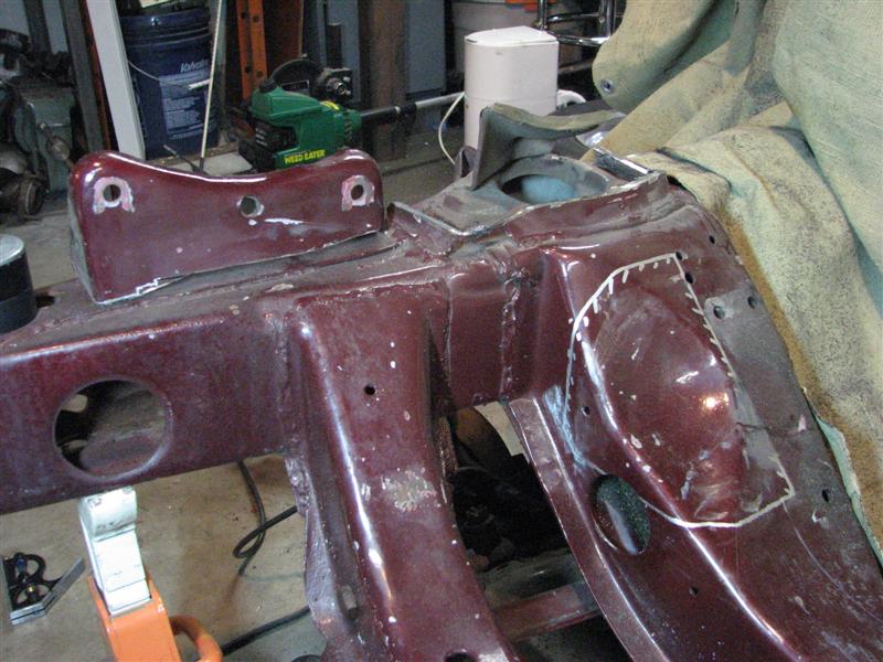
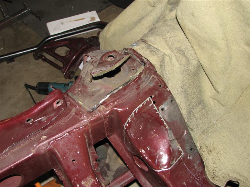
It took quite a bit of cutting and grinding to get the remnants of bracketry off the frame. Once the frame was flat and clean of the old stuff, I went to work carefully trimming the tower until the holes lined up with my jig.
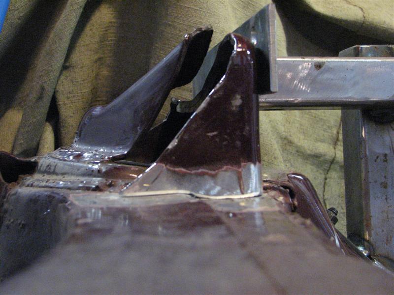
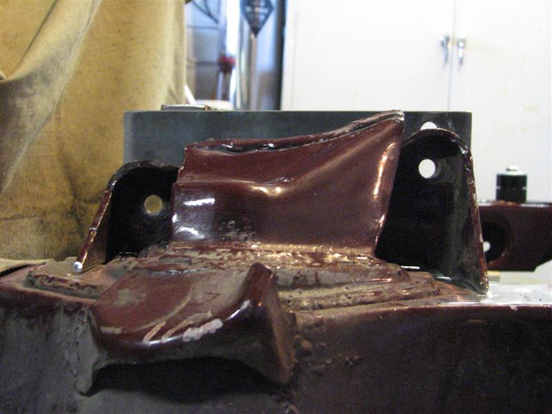
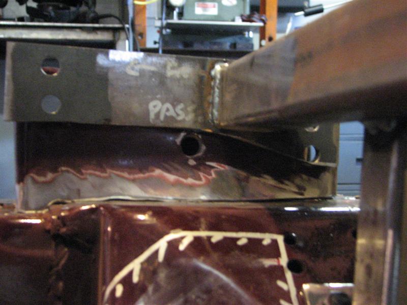
I have one problem area in near the back of the tower in this photo. You can see in that area there is a gap with the frame. The crossmember has a piece that overlaps and is welded onto the frame channels. I cut so it would line up with the top of that surface. Unfortunately it didn't extend far enough so that after the trimming, the UCA tower no longer intersects it. The gap is about 1/8" and I will probably fill it with weld before tacking the tower back in for final welding.
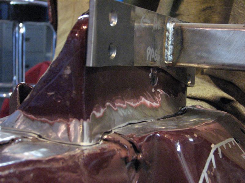
My next problem will be trimming the shock tower area in a way that doesn't move the upper shock mounting position. That will be fun!Clint - '70 Nova "restomod" cruiser & autocross family car
04-17-2011 #19
Registered User
- Join Date
- Jul 2010
- Location
- Monticello, MN
- Posts
- 249
One of my friends and I were discussing this variation of the G-mod and wondered or didn't realize how you accounted for the shock mount. I guess that this thread should explain and save a thousand words in the process. Nothing like a bunch of great pictures to alleviate the "Doh!!" factor.
PS. Both my folks are survivors too Clint, and each rounding the 72 mark this May and June.
04-18-2011 #20
Registered User
- Join Date
- Nov 2010
- Location
- Ventura County CA
- Posts
- 556
I haven't done my shock mount yet, but here is a picture of how someone else did it http://i17.photobucket.com/albums/b6...o/104_1782.jpg and here is their thread with a little more explanation.
Congrats to your folks!Clint - '70 Nova "restomod" cruiser & autocross family car

 Reply With Quote


