


Results 1 to 20 of 35
Thread: bellhousing alignment
-
08-17-2009 #1

 Registered User
- Join Date
- Jun 2009
- Location
- Decatur, AL
- Posts
- 130
bellhousing alignment
Alright, so I just spent the better part of the night doing my bellhousing alignment with a dial indicator and magnetic base. Let's just say that it was a pain in the butt also. I had problems getting a reading that could be reconfirmed with each pass. I took a reading at every 45 degrees for four passes and each pass came up with something different almost with some reading the same. I was taking the reading from the outer exterior lip and I think since it has breaks in it it made the dial change. I didn't take it on the inner lip since that's where it's welded and the weld is not a continuously flat surface. I tried taking it from the inside of the bellhousing thinking it was a concentric circle but apparently the powdercoating has different densities on the interior also.
Here's a pic:

You can see the dial indicator also and the lip it is riding on. Some of the times it hit one of the breaks in the lip and then tried to pick up afterwards it seemed to "jump the track". I think this was throwing off my readings also and screwing with the indicator.
Anyway, here's the readings:
0 degree reading: 1st: -.010 2nd:.000 3rd: -.002 4th: -.002
45 degree reading: 1st: -.003 2nd: .007 3rd: .005 4th: .005
90 degree reading: 1st: .000 2nd: .010 3rd: .013 4th: .010
135 degree reading: 1st: .011 2nd: .012 3rd: .010 4th: .012
180 degree reading: 1st: -.006 2nd: .005 3rd: .003 4th: .003
225 degree reading: 1st: -.011 2nd: -.001 3rd: -.001 4th: -.003
270 degree reading: 1st: -.014 2nd: -.006 3rd: -.007 4th: -.009
315 degree reading: 1st: -.017 2nd: -.008 3rd: -.006 4th: -.009
As you can see my last two readings seemed to be a little more accurate. My baseline "zero" reading was actually setup at 90 degrees hence the first reading of zero there. It was just easier to setup the dial indicator at that position for me.
So, how should I go figuring up my information? Should I average the last two sets of numbers and get my low and high numbers to figure out what type of offset dowels to use?
Any suggestions appreciated. 2001 Camaro Z28 (DD)
LS3 525hp GM crate engine, built 4L60e
1974 Camaro Z28 Type LT
Solid roller 355 sbc with T-56
-
08-18-2009 #2
Starting The Transformation
- Join Date
- Dec 2008
- Location
- Knoxville, TN
- Posts
- 363
Hey kyphur,
good work on documenting your dial in. you are on the right track on your assumptions:
- powder coating is messing up your reading
- indicator is "jumping track" and throwing your numbers off
- numbers are not repeating like they should
I've marked up your pic with some colored arrows and a legend on what changes to make.
Also, watch the bellhousing dial in how-to video. This Hi-LOW 2point method is easier.
If you still get erratic readings, then a couple of factors could be going on:
- your indicator is not rock solid. it may be moving at the joints or the base. (you won't be able to see it move to create the error in readings)
- the bellhousing bore may not be round
- there may be small burrs or dents in the bellhousing bore
As to the dowel pins, I'd recommend you pick up some .007inch but it's not clear if you will need them yet.
ShafiLast edited by KEISLER; 08-18-2009 at 04:58 AM.
-
08-18-2009 #3
Registered User
- Join Date
- Jun 2009
- Location
- Decatur, AL
- Posts
- 130
In the video they only have two reference points (the -1 and the +6). Was this taken at the "maximums" of the values or just two reference points randomly chosen? If I do my two maximums (.012 and -.009) in what I believe is my most accurate reading and which are also 180 degrees apart from each other that gives me a measurement of .003 divided by half which is .0015 right? That's if I did the measurement correctly right?
2001 Camaro Z28 (DD)
LS3 525hp GM crate engine, built 4L60e
1974 Camaro Z28 Type LT
Solid roller 355 sbc with T-56
-
08-18-2009 #4
Registered User
- Join Date
- Jun 2009
- Location
- Decatur, AL
- Posts
- 130
O.K. Just rewatched the video. My .003 that I stated up above is run out and then when you divide it by half you're getting your offset numbers. So if my .003 run out is correct then I would be safe with this install. Then if I wanted to nail it 100% I would use offset dowels for .0015 in the direction of my positive number (.012) to clear it up and center it.
2001 Camaro Z28 (DD)
LS3 525hp GM crate engine, built 4L60e
1974 Camaro Z28 Type LT
Solid roller 355 sbc with T-56
08-18-2009 #5
Starting The Transformation
- Join Date
- Dec 2008
- Location
- Knoxville, TN
- Posts
- 363
Bellhousing Dial In
OK, good question. Let me explain about how runout works with regards to the bell and the crank.
First, there is a difference between the true center of the crankshaft, and the true center of the bellhousing. The straight line (radial direct) amount of difference, in inches, is OFFSET. The Offset multiplied by 2 will be the RUNOUT.
You can break down the Offset as a vector in X and Y axis, then make the corrections in the equal, but opposite directions, to get the true centers in line with each other. That is one way to go about dialing in the bell, but it requires you to take the square root of the sum of the square of each x and y component to get the radial distance, but this is somewhat cumbersome.
The other method is the way I explain in the video - the Min Max method. Using the Min Max method, you don't have to fuss with the x/y-component math. The Max runout point, should be 180 degrees opposite the Min runout point. If you think about it, the Max runout point is where the bellhousing bore is farthest away from the indicator, and the min point is where the bore is the closest to the indicator. Once you find out the amount of the two value, then you have determined how much offset you have (the difference divided by 2), and you can select the right dowel pin.
It makes the math a little easier to understand if you find the Min point, and set your indicator dial to zero. Let's say you do this, and you find the runout as follows:
MIN = zero'd out at 18 degrees
MAX = .012 inch at 198 degrees
Then this says you have 12thou runout, which is 6 thou (.006) offset, so you need a 7 thou (.007) offset dowel pin set to correct for it. When you install the offset pins at 198-180=18 degrees direction, you will create a resultant offset of .001 in the direction of 18 degrees, which is .002 runout = within spec of .005 runout = EXCELLENT.
What can complicate the measurement and correction of runout is when the bellhousing bore is not a circle, but an oval, which is usually caused by incorrect machining setup at the supplier. Also, burrs, dents, paint, etc creates problems, so be sure to remove this using a file or burr removal tool. When we do an install, we mask off the back face and the bore before doing any painting. Same goes for powder coating.
Hope this helps!Last edited by KEISLER; 08-18-2009 at 09:29 AM.
08-18-2009 #6
Starting The Transformation
- Join Date
- Dec 2008
- Location
- Knoxville, TN
- Posts
- 363
kyphur, Originally Posted by kyphur

you got it, man!
08-18-2009 #7
Registered User
- Join Date
- Jun 2009
- Location
- Decatur, AL
- Posts
- 130
Yes, this makes tons of sense and simplifies the process a lot. Thank you for all your help!
2001 Camaro Z28 (DD)
LS3 525hp GM crate engine, built 4L60e
1974 Camaro Z28 Type LT
Solid roller 355 sbc with T-56
08-18-2009 #8 Registered User
- Join Date
- Aug 2004
- Location
- Walla Walla, WA
- Posts
- 1,512
 Nice write-up. Thanks for making this often frustrating task a little easier. Originally Posted by KEISLER
Mike Kelcy - '68 Camaro with some stuff done to it.
08-18-2009 #9 Registered User
- Join Date
- May 2005
- Posts
- 209
Jason
We sell Quicktime housings and are very familiar with their design. We often speak with Ross McCombs the President of Quicktime about his housings and are very confident of the quality of their product, however alignment of this bell housing to the T56 can not be checked by the method you are using. The T56 uses alignment dowels that plug in to the bell housing to secure it in the proper location. The area you are measuring on the 6023 Quicktime bell housing for SBC to a T56 was not designed with this intention. It will however tell you that your housing is centered on the dowel pins on the engine but won't tell you if the transmission is lined up which is the main reason for doing this in the first place. Quicktime machines the area you are measuring to give you at least part of the puzzle but you have to rely on Quicktime to have the mating holes for the transmission dowel pins in the correct location to achieve proper alignment which they very carefully make sure they do. The TKO, Muncie, BW T10 and others use the retainer on the front of the transmission to mate with the register bore on the bell housing to ensure proper alignment. T56 factory adapters and most aftermarket housings were not designed to be measured by this method because there is no place to put the dial indicator. Measuring these housings would require special tools designed for this purpose and are not readily available to purchase at your average tool store.
Another thing I noticed in your picture is the engine block dowel pins. It may be the picture angle or lighting but it does not appear that your dowel pins are long enough. The bell housing must sit on the flat part of the dowel and not on the tapered edge. Longer dowel pins are available from several manufacturers. I like the Moroso brand as they seem to be more accurately machined and fit better.
The purpose of this post is not to correct ANYBODY but to inform anyone using a bell housing for a T56 that they usually can not be measured without going to extraordinary means. Most of the time you have to trust that the manufacturer has done his job correctly.
08-18-2009 #10
Starting The Transformation
- Join Date
- Dec 2008
- Location
- Knoxville, TN
- Posts
- 363
Jim, that is not correct with this bellhousing in question. The bore is machined on the same setup as the other tranny side features, including the trans dowel pin holes - and IS the only way to get a valid dial in measurement. Everything is there to get the dial in. A quick guy check on typhur's numbers shows he is already close. This is not an accident.
You cannot soley rely on the bellhousing to be correct, it has to be dialed in with the engine as an assembly. [this gets back to the fact that there is no such thing as a pre-dialed in bellhousing] The purpose of bellhousing dial in is to get the assembly of bell to engine aligned - thus eliminating any out of tolerance machining in the engine line bore process, engine dowel pins, bellhousing dowel pins, bellhousing bore - ALL of these features taken into consideration as a whole.
There will never be an alignment tool made available to measure the alignment of two sets of dowel pins (engine and t56) to the engine crank - it is not feasible. Unlike the McLeod t56 modular bell where you cannot pick up a concentric bore, Ross did a good thing putting a bore in his t56 bellhousing back plate, and kyphur should simply clean off the paint, recheck his numbers, and make the offset correction as needed with Moroso, Lakewood or xyz brand dowel pins. I personally like the Moroso pins better, but they don't come in all size ranges.Last edited by KEISLER; 08-18-2009 at 11:35 AM.
08-18-2009 #11
Registered User
- Join Date
- Jun 2009
- Location
- Decatur, AL
- Posts
- 130
I think I'm misunderstanding what you're saying there. There is a tool that measures it really simply but I just don't have 140+ bucks for it. Plus I don't think it would work with my bellhousing due to the huge opening compared to a traditional bellhousing. Originally Posted by KEISLER
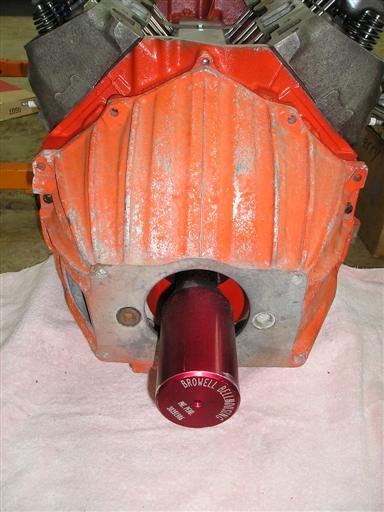
You can find a link to it's usage here.
I received an email from Ross earlier today but I can only access it on my phone since I'm work. He looked at my setup and said I was on the right track and that was the best place to get the measurement from if I remember the email correctly. He said the transmission mounting flange is what I should be measuring from for concentricity since it's cylindrical to the input shaft and based off the transmission's mating surface (again, IIRC). Originally Posted by KEISLER
Also, what about the Lakewood EZ install dowel pins? They look pretty easy to setup but I'm just worried about them loosening. I doubt it would but in the end you never know. 2001 Camaro Z28 (DD)
LS3 525hp GM crate engine, built 4L60e
1974 Camaro Z28 Type LT
Solid roller 355 sbc with T-56
08-18-2009 #12
Registered User
- Join Date
- May 2005
- Posts
- 209
The Browel tool you see in your picture is a go/no go tool. It will not tell you how far you're off. And no, a feeler gauge won't be accurate enough.
08-18-2009 #13
Starting The Transformation
- Join Date
- Dec 2008
- Location
- Knoxville, TN
- Posts
- 363
Bellhousing plug gauge
kyphur,
That's a good post you made about your conversation with Ross. It confirms what you were doing and what I said about the ability to check dial in on this particular bell.
The gauge you are showing is a plug gauge, and it won't benefit you (or anyone else in my opinion). To make something like a plug gauge work, you have to remove the pilot bearing first, then this gauge has to be super high precision to achieve what is called a SLIP FIT. A Slip Fit has a typ .0005 clearance, and since the repeatability of crank shaft diameter is not going to hold that size, the gauge would either fit too loose, or be so tight you would have to beat it in with a hammer. Even then, I bet you could still move it around more than .005inch any one direction.
The dial and test indicators are the best tools to check for bellhousing to crankshaft runout. You are using a dial indicator. Our video uses a test indicator. Test indicators typically have 2x the resolution and accuracy, and but much less working range.
08-18-2009 #14
Registered User
- Join Date
- Jun 2009
- Location
- Decatur, AL
- Posts
- 130
Yeah, he's a stand up guy and has answered a lot of questions for me. This is my first manual setup I've done by myself and I've never done a bellhousing alignment check before. Having the responses from you, Ross and others has made me a little more confident that I'm on the right track. Originally Posted by KEISLER
2001 Camaro Z28 (DD)
LS3 525hp GM crate engine, built 4L60e
1974 Camaro Z28 Type LT
Solid roller 355 sbc with T-56
08-18-2009 #15
Registered User
- Join Date
- May 2005
- Posts
- 209
I think you should read my post again. I'm saying the Quicktime housing is machined this way intentionally and that it will tell you only that it's centered over the crank. The dowel pin holes for the transmission are drilled at the same time based on the engine dowel pin location. This is something you must trust the manufacturer to do correctly because the average guy doesn't have the means to measure this. Originally Posted by KEISLER
Example. Measure this one.
As far as no such thing as a pre-dialed in bell housing goes, manufacturers all over the world build engines and associated parts in completely different locations and they all meet in one location for assembly. GM bell housings were made to fit their engines and they are built from drawings to specific tolerances. Our Aluminum housings are built to the same measurements and tolerances using GM drawings as are Quicktimes housings. If you have a new GM engine or you have an old GM engine and you're certain of it's history (no line boring etc.) you could bolt on any of these housings and not be concerned about measuring it. After all if you could still buy a 621 housing from GM would you measure it if you were installing it on a new GM engine? GM didn't. I will agree that if you are in doubt of your engines history or you have had it line bored or you are installing a housing that is known not to be made to original specs you must measure it. Otherwise it's just for piece of mind.Last edited by GMJim; 08-18-2009 at 12:59 PM.
08-18-2009 #16
Starting The Transformation
- Join Date
- Dec 2008
- Location
- Knoxville, TN
- Posts
- 363
like I said, it's not about the single component. It's about the assembly of the components. We machine our bells to within .0015 runout of bore to dowel pins and STILL require the customer to do the dial in. why? because it is the assembly of the components. Originally Posted by GMJim
apples and oranges comparo ... here's why: Originally Posted by GMJim
new engines, new bellhousings of today, including the T56-LS bell shown above, are certified by the manufacturer during the Pre Production Approval Process (PPAP). This is the QS9000 term for validation of a product, and anyone that comes from the OEM Automotive Industry like we do at Keisler, know this term well. so GM dictates the engine and transmission mounting features, and GM and Hydramatic and Tremec, etc have to pass the PPAP inspection.
the Aftermarket is different ... QS9000 is not in place, most companies make parts as best as they can, and roll with it. Parts are mixed and matched by the end user - new and used. History is unknown, etc etc - you know.
that is why this 1 hour inspection technique should be used when it can. if it cannot be, like the T56-LS bellhousing shown above, it is omitted. keep in mind that the LS engine is purely a production engine built to QS9000 standard of product quality and traceability. therefore, the likelyhood of there being a problem with two OEM parts is not very high.
I think you are incorrect on this point. The FSM (factory service manual) of many of our classic cars spells out this inspection practice as standard. Check the one for your Camaro. I know the one for my '70-71 Mopars has the requirement, and I am fairly certain the FSM for our '65 Vette had the same proceedure. Originally Posted by GMJim
At the end of the day, it's a small piece of time, for a big upside of piece of mind. For all of our manual transmission products going into classic cars, it is THE step that validates our warranty. That's how important we think it is. And the Tremec sheet that comes with the TKO stated the same thing for many years - must be within .005 runout.
BTW - good discussion by ALL.Last edited by KEISLER; 08-18-2009 at 01:38 PM.
08-18-2009 #17 Registered User
- Join Date
- Mar 2009
- Location
- Kansas City area
- Posts
- 365



You definitely need longer dowel pins with the quick time bell if you install the block saver plate.
08-18-2009 #18
Registered User
- Join Date
- May 2005
- Posts
- 209

08-18-2009 #19
Starting The Transformation
- Join Date
- Dec 2008
- Location
- Knoxville, TN
- Posts
- 363

08-18-2009 #20 -Moderator-
- Join Date
- Jul 2005
- Location
- Mountain View, CA
- Posts
- 9,583
Hey fellas,
Great exchange of TECH!True T.
Whats new with Project 1/2-Trak?
Follow my wisecracks on Sports, Food, Politics and other BS on Twitter.
My blog
When they kick out your front door, How you gonna come?
With your hands on your head, Or on the trigger of your gun?

 Reply With Quote