


Results 21 to 40 of 64
Thread: gpmm ls3 controller help
-
10-28-2015 #21
 Registered User
- Join Date
- Feb 2011
- Location
- dallas, tx
- Posts
- 1,731

ok so the blue fan wire coming from the ecu is still only a on and off feature no matter how many fans are hooked up to it correct?
In the GMPP harness since theres only one wire and not two i can have run two fans in parallel and that won't overload the relays or fuses in the supplied fuse box?
Reason I'm asking is because would it be better to run the ecu trigger wire to both fans to kick on when the temp is reached and but also if the ecu didn't trigger the the fans to turn on the AC unit would atleast turn the secondary fan on when the ac is on?
Am i correct on the gauge wiring? Just run the single signal wire from the ecu bulkhead for each of the oil, tach, and speedometer ?
I noticed on the back of my automater speedometer there is actually a output signal on it. Could that be used to trigger the reverse lockout solenoid?
-
10-28-2015 #22
Registered User
- Join Date
- Feb 2011
- Location
- dallas, tx
- Posts
- 1,731
according to this it looks like i just run the vss one signal wire from the bulkhead to the gauges. It doesn't say anything about output though.
http://www.autometer.com/media/manual/2650-1164.pdf
-
10-28-2015 #23
 -Moderator/Sponsor-
- Join Date
- Jun 2001
- Location
- Orlando, FL
- Posts
- 10,604
Yes, that's right. Originally Posted by IceMan
You will need to have one fuse and one relay per fan. What I like to do is split the fan control signal and rewire the fuel pump relay to be the second fan, then pull the fuel pump signal back to the back of the car, and put the fuel pump relay in the back of the car. Just remember that the fan control signal is a ground, and fuel pump signal is 12v. Originally Posted by IceMan
You'll need to wire in a trinary switch that overrides one of the fans. I can help with that wiring. Originally Posted by IceMan
Depends on the gauges. Tach and Speedo should be fine, but oil might not match between the GM sensor and your gauge. Originally Posted by IceMa
Not the solenoid itself (which is looking for a ground signal), but maybe the Samaco unit can use that signal. Originally Posted by IceMan
John Parsons
UnRivaled Rides -- Modern upgrades for your ride.
UnRivaled Rides recent project -- LS9-powered 69 Camaro
-
10-28-2015 #24
Registered User
- Join Date
- Feb 2011
- Location
- dallas, tx
- Posts
- 1,731
according to the GM rep
- Hook the vss output wire ( brown ) from the bulkhead to the speedometer signal wire
- Hook the tach ( white ) from the bulkhead to the gauge tach signal wire
- Hook the Oil pressure ( Tan/white ) from the bulkhead to the gauges signal wire
- For the water temperature, there is a port located on the right side (passenger side) of the engine, in the cylinder head, past the last exhaust port (closest to the firewall / flywheel). There is a plug threaded in this location, that can be removed. This threaded in plug will either require an 8mm Allen Wrench, or a T52 Torx bit. There will be no noticeable difference in temperature reading when using the shorter sender. The 2277 adapter requires a 3/4" wrench, and the 2259 sender requires a 12mm wrench. Be careful to only tighten the adapter into the head until the crush washer is flattened. Do not over tighten.
- for the voltmeter just hook up the ignition wire from the gauge harness to the gauge
Looks like I'm buying the samaco unit. Read stories of some issues wiring it to the brake switch.
-
10-29-2015 #25
 Registered User
- Join Date
- Aug 2004
- Location
- Jacksonville, FL
- Posts
- 1,666
Are you sure the oil signal wire from the bulkhead will be compatible with an autometer type gauge? I am using the VHX gauges with my GMPP harness and when I was setting it up I had to select CAN BUS for the gauge to work. That stubby sender that autometer sells works really well (with adapter). Nice and compact unit.
Chris
1968 Chevy Camaro SS
LT4 (coming)/T56 DSE suspension
1969 Oldsmobile Cutlass S convertible (442 Clone)
LS3/4L70e, DSE suspension

-
10-29-2015 #26
Registered User
- Join Date
- Feb 2011
- Location
- dallas, tx
- Posts
- 1,731
according the the gm rep he said it will. Honestly i will let you know when i get it fired up. Trying to do all my wiring now and hoping i only have a few things to rethink about.
-
10-30-2015 #27
Registered User
- Join Date
- Feb 2011
- Location
- dallas, tx
- Posts
- 1,731
Maybe I'm just overthinking it? Does this sound right or I'm i screwing something up?
So far i removed the lt blue wiper wire ( wiper high speed ) dk blue wiper wire ( washer pump ), black ground wire ( wiper low speed ), white wire ( washer and high speed wiper ), purple wire ( vss signal ), Yellow ( vss ground ), orange wire ( Heater blower ), dk blue ( oil pressure ), White wire ( tach ), wires from the engine bulkhead connector
That leaves me with 5 wires :
- starter Red wire - Goes to the battery lead on the starter solenoid. Runs from the bulkhead connector to brown connector. Seems like i can just ignore the brown wire and connect it directly the red wire. Run the same color red wire from the back of the alternator to the starter which goes on the same stud as the red bulkhead connector wire. This same spot that i run this wire the battery also connects on here. Battery gives the system 12v but once the car starts the alternator then feeds all of this
- ecm Red wire - Didn't use this wire in the engine harness but still in the bulkhead since the power source and ecm are inside the car. This is the battery feed wire. I can prob run it off of the studs on the gmpp pole or to the firewall bulkhead connector. Is this the feed wire for the ecm power or a 12v input from the ecu output to feed the cars 12v constant source? sounds like its the feed wire for the ecm but if I'm connecting the gmpp fuse box directly to the battery bulkhead this wire shouldn't be needed right?
- Starter pink wire - This wire would get routed to the ballast resistor which the other end of the ballast resistor would connect to a distributor ( which i don't have ) and then the R side of the starter solenoid. Would i just run this wire to the starter solenoid? Is this then my ignition output for my entire car?
- ecm Pink wire - didn't use this wire in the engine harness but still in the bulkhead since the ecm and power feed are inside the car. Is this the ignition feed in for the ecu or ignition feed out from the ecu for the cars ignition system?
- Purple wire - ran to the S part on the starter solenoid. This is prob the output from the ignition to complete the starter circuit to engage the starter solenoid to start the car.
Extra info.
My battery bulkhead is on the passenger floor board
To supply my ecm with battery power I'm going to run my power wire from my bulkhead connector to the ecm which is beside each other.
-
10-30-2015 #28
Registered User
- Join Date
- Aug 2004
- Location
- Jacksonville, FL
- Posts
- 1,666
What oil pressure sender are you running? Are you running the factory oil pressure sender? Just curious if the GM CAN signal doesn't work with your gauge, you could always put the aftermarket one in either the factory location (back side of manifold or above the oil filter). I rewired my entire car with the AAW Classic Update harness at the same time and didn't need a good percentage of the "factory" wires when using the VHX gauges and their ODB2 module to take the reading directly off of the PCM. I also integrated the DSE wiper into it also (don't know what wiper you are running- if any). I removed most of the wires from the engine bulkhead and repurposed them for other stuff (like reverse lockout and such). I wanted to reduce the amount of wires going into the inside of the car because I had smoothed the firewall. Here is an example that I did. If you changed wires around, plan it out
Chris
1968 Chevy Camaro SS
LT4 (coming)/T56 DSE suspension
1969 Oldsmobile Cutlass S convertible (442 Clone)
LS3/4L70e, DSE suspension
-
10-30-2015 #29
Registered User
- Join Date
- Feb 2011
- Location
- dallas, tx
- Posts
- 1,731
Yes I'm running the factory oil pressure sensor. If it doesn't work ill just run another one
yes using the odb2 module would have been much easier. Might upgrade later down the line. Gauges and all
The dse wiper is going to run into the harness also. Thats why i removed the factory wiper wires. I already have the dse wiper motor.
Yup i removed every wire that isn't being used. Eventually i will repurpose the unused ports. Trying to do that all now before installing it. Its funny how you have it laid out in your head and people walk by you looking at you funny because you are tied up in all the wires lol. Im also removing the wires one by one with the clips attached so if i need to reuse i just clip them back in instead of cutting them out.
Everything will route into the ecm fuse panel or the AAW kit. My samoco unit should show up next week for the reverse lockout. Wasn't sure how else to do it
-
10-31-2015 #30
Registered User
- Join Date
- Feb 2011
- Location
- dallas, tx
- Posts
- 1,731
tach info>>>>>
Originally Posted by Vega$69 View Post
For the autometer tach to work you will to install a step up resistor and will set the dip switches to 4 cylinder 2 pulse.
http://www.autometer.com/media/2650-1563.pdf
Listed are the most common ways to hook up a tachometer signal wire to the most popular applications that tend to have an existing tachometer signal:
• 98 F Body: Pin #35 of the blue PCM connector.
• 99-02 F Body: Pin #10 of the red PCM connector.
• LS equipped truck applications: Pin #10 of the red or green PCM connector (it will be either red or green, it will not have both). Not all trucks will have a tach signal wire.
• 97-98 Corvette: Pin #35 of the blue PCM connector, white wire. • 99-04 Corvette: Pin #10 of the red PCM connector, white wire.
• 05-06 Corvette: Pin #48 of the blue PCM connector, white wire. • 07-09 Corvette: Pin #48 of the black PCM connector, white wire. • 04 GTO: Pin #10 of the green PCM connector, brown wire.
• 05-06 GTO: Pin #48 of the blue PCM connector, brown wire.
• 05 Cadillac CTS 5.7L: Pin #10 of the green PCM connector, white wire.
• 06-07 Cadillac CTS 6.0L: Pin #25 of the blue PCM connector, white wire.
All of the above will require the tachometer to be set for 4 cylinder, 2 pulse signal. If the tachometer fails to operate, there are several ways to handle this. Each
case may be a little different.
If the tachometer does not function:
You may check the original tachometer circuit. You can do this with a digital voltmeter.
• Connect the positive lead of the voltmeter to the tachometer signal from the PCM.
• Connect the negative lead of the voltmeter to a good chassis ground.
• With your meter set on DC volts, start the engine.
• Monitorwhatyouhaveatidle.Youshouldhavealowfigureth atrangesanywhere from 0.5 to 3.0 volts (and remains rather steady).
• At a high-raised idle, it should be significantly more. As an example, if
you measured 1.0v at idle then at a raised engine speed you may see 3v, or more.
• There is no “spec” for the amount of volts you will see. What you are looking for is an increase. For example: If you saw 1.0v and idle, then measured 1.1v with raised engine speed, then that signal is not changing, or operating normally.
• If there is little to no activity, you may use a resistor to try and restore the weak signal. Installing the resistor: Use a 10K, 1/2 watt resistor (supplied in the LS Installation Kit). Solder one leg of the resistor to the tachometer signal circuit. Solder the other leg of the resistor to a 5v reference circuit.You may use a wiring diagram that pertains to your engine computer to determine what pin #, and wire color will be a 5v reference. *Hint: GM most commonly tends to use a solid gray wire for 5v reference, however you will still want to verify this with your wiring diagram, and a voltmeter set to DC volts. Do NOT use a 12 volt power supply or source for this. This may cause damage to the PCM.
10 7
Tachometer
If the PCM supplied tachometer circuit functions, but the tachometer does not: Take normal steps in diagnosing the tachometer. You may also try the tachometer on another vehicle. If it works on another vehicle, but not on your LS engine, then check the date code of the tachometer. Some older units (manufactured prior to 2007) may require a 5v calibration. All newer Auto Meter tachometers should not require this modification. Autogage tachometers may or may not function and CAN NOT be modified for 5v calibration.
If the PCM supplied tachometer circuit does not function, and you have already tried the pull-up resistor:: This will then require using a tachometer adapter. This is not uncommon when the computer (PCM/ECM) has been re-programmed or flashed. Some LS applications may have no wire for tachometer signal, or the computer may simply produce no tachometer signal. In this case a 9117 tach adapter will be required. The following details the steps required to install the 9117 on an LS engine.
Most commonly with original, and aftermarket engine wiring harnesses, the ignition coil power supply wire color is pink. Any applications using the adapter will be calibrated to 8 cylinder, 4 pulse.
Cut the pink power supply wire at each bank, prior to the coils splitting. This pink wire can be cut just prior to the wiring connector at the center of each valve cover.
• The cut halves coming from the harness (not the halves going to the coils) will still have power when the key is on. Join the left and right bank power halves together. Splice these two power halves (now together) to the solid red of the 9117 adapter.
8
• Now, join the coil-side cut halves together (left and right bank).
• Splice these two coil halves (now together) to the red wire with a green stripe
of the 9117 adapter.
• Ground the black wire of the adapter to an engine ground.
• Thegraywireoftheadapterwillbeyournewtachometersign al.Youdonot
want to try to “cheat” and use just one bank of coils, as the signal will appear
very erratic.
If the tachometer now functions well, but quits when above “x”-amount of RPM such as 4,000, then a shunt resistor will be needed. This is a 0.1 ohm, 3 watt resistor. Connect one leg of the resistor to the red adapter wire, and the second leg of the resistor to the red/grn adapter wire. This will allow some of the current to bypass the adapter, and still allow the tachometer adapter to function.
-
11-14-2015 #31
Registered User
- Join Date
- Feb 2011
- Location
- dallas, tx
- Posts
- 1,731
Current bulkhead layout.
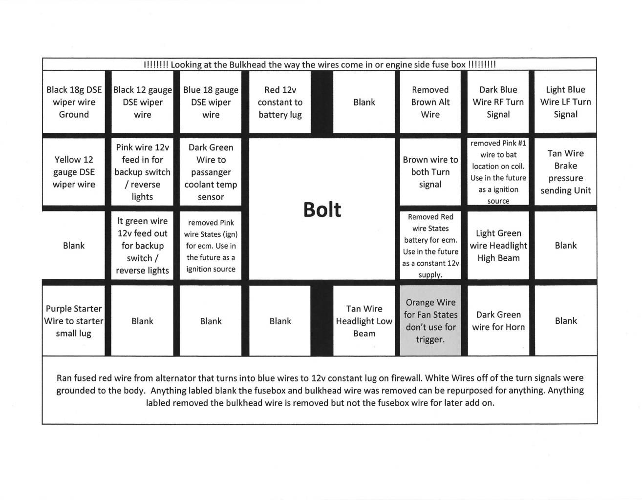
diagram for my transmission harness

-
11-23-2015 #32
Registered User
- Join Date
- Feb 2011
- Location
- dallas, tx
- Posts
- 1,731
which wire is the signal wire for the vss? Theres two. Originally Posted by 130fe

-
11-23-2015 #33 -Moderator/Sponsor-
- Join Date
- Apr 2001
- Location
- The City of Fountains
- Posts
- 16,129
Doesn't matter. Ground one and use the other as the signal. Originally Posted by icemanrd19
Andrew1970 GTO Version 3.0
1967 Cougar build
GM High-Tech Performance feature
My YouTube Channel Please Subscribe!
Instagram @dr__efi
I deliver what EFI promises.
Remote Holley EFI tuning.
Please get in touch if I can be of service.
"You were the gun, your voice was the trigger, your bravery was the barrel, your eyes were the bullets." ~ Her
11-23-2015 #34
Registered User
- Join Date
- Feb 2011
- Location
- dallas, tx
- Posts
- 1,731
two wires connect into the vss. Now for the samoco unit i have to tap the correct vss signal. i know it doesn't matter if i was just hooking up the vss but the vss is already connected and i have to figure out which one is the signal wire from the ecu
11-23-2015 #35
Registered User
- Join Date
- Feb 2011
- Location
- dallas, tx
- Posts
- 1,731
Also for the ricks vapor works tank is this correct.....
Fuel level sending unit
- Black wire with white stripe. Ground one end to the body and the other end to the outside area of the fuel level sender top
- Tan wire. Goes in the middle of the fuel level sender top and other end to the gas gauge
fuel pump
- Black wire ground to the body from the harness
- Gray wire run from the harness to the gmpp controller fuel pump wire which i think is also gray
12-07-2015 #36
Registered User
- Join Date
- Feb 2011
- Location
- dallas, tx
- Posts
- 1,731
This is how its wired. Should work fine. Originally Posted by icemanrd19
Im completely done with wiring except radiator fan wiring. Can anyone help me?
GMPP fuse box fan wire directly to my fans in parallel. One wire going directly to my fan then splitting to a secondary relay to trigger the second fan. Signal wire coming from my vintage air kit to turn on my secondary fan only. This way both fans can turn on if the ecu tells it too but if the engine temps aren't high enough the vintage air unit will only turn on the secondary fan while the ac is running.
12-08-2015 #37
-Moderator/Sponsor-
- Join Date
- Jun 2001
- Location
- Orlando, FL
- Posts
- 10,604
Yes, that will work fine. You will need a power source for the 2nd fan relay so the trinary switch can enable the 2nd fan when the ECM isn't calling for a fan.
John Parsons
UnRivaled Rides -- Modern upgrades for your ride.
UnRivaled Rides recent project -- LS9-powered 69 Camaro
12-13-2015 #38
Registered User
- Join Date
- Feb 2011
- Location
- dallas, tx
- Posts
- 1,731
The line coming from the GMPP harness is it a ground or 12v feed?
#1 where does the feed from the GMPP harness go to so it ties into the passenger fan? Im guessing #86 since i think its a ground
#2 Sorta the same question as above. Is the gmpp line a ground or 12v feed? If a ground Then i would need to supply the fan with a 12v feed. If its a 12v feed then run that wire directly to the positive on the fan and ground the fan.
#3 Do i need a relay between the GMPP kit signal wire to the drivers side fan since the line is already fused and relayed according to the instructions?
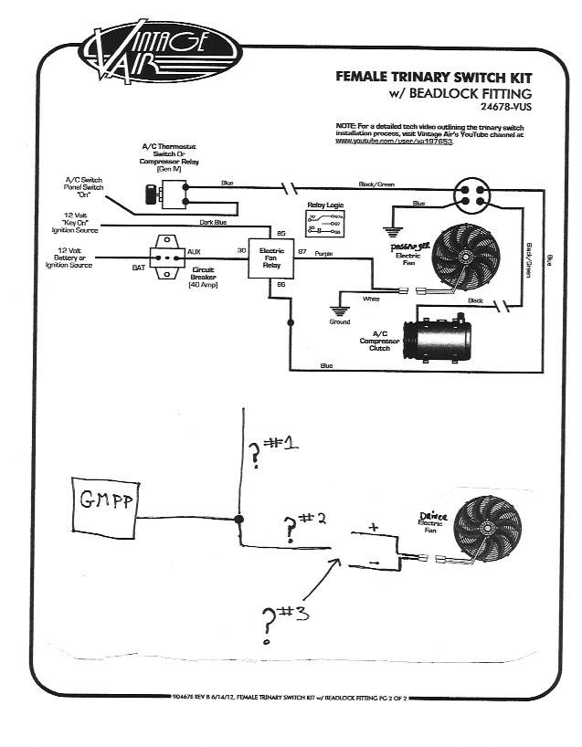
12-14-2015 #39
Registered User
- Join Date
- Feb 2011
- Location
- dallas, tx
- Posts
- 1,731
Bump. Trying to finalize this on sat. After that run the 2 coolant lines and power steering lines so i can start this thing
12-15-2015 #40
Registered User
- Join Date
- Feb 2011
- Location
- dallas, tx
- Posts
- 1,731
anyone else seen this?
http://www.gm-efi.com/news/pcm-ncs-g...ctric-fan-kit/

 Reply With Quote