


Results 1 to 20 of 25
-
10-27-2011 #1
 Registered User
- Join Date
- Aug 2008
- Posts
- 59
Should I align frame before welding SFCs in first gen?
I'm about to have subframe connectors welded to my 68 Camaro with an LSX. I don't know whether the frame has been in an accident, whether the front and rear frames are square with themselves and/or each other. Car seemed to drive straight and now I put in solid body mounts (one side at a time - haven't tested it at speed).
If the car runs straight at speed and aligns fine, how big of a deal is it to make sure the frame is perfectly square? I tried measuring it but I am not quite sure that my measurements are accurate. I went to a collision shop and they told me 8-12 hours of labor just to measure the frame. I promptly left. I assume welding SFCs will make the front frame impossible to move relative to the rear. Do you guys think it will be ok to just weld up the SFCs and go, or should I make sure the frame is 100% straight first?
-
10-27-2011 #2 Registered User
- Join Date
- Sep 2004
- Location
- Metamora, Illinois
- Posts
- 1,619
I would make sure it is square first. Its not that difficult to check, but it will be harder to adjust with the engine/trans installed.
10-27-2011 #3
Registered User
- Join Date
- Jan 2010
- Location
- Elk River, MN
- Posts
- 676
There should be some tricks to aligning it in your own garage/shop. I'd at least want to check it for peace of mind before welding everything up solid.
-mattMatt Peterson 84 Monte Carlo - Sold :( | 99 Corvette Racecar | 2001 Z06 Daily Driver
https://www.pro-touring.com/showthre...ng-Bertha-Back
http://ls1tech.com/forums/conversions-hybrids/1499192-84-monte-5-3-build.html
https://www.pro-touring.com/threads/...rvette-Racecar
10-27-2011 #4 Pro-Touring.com Sponsor
- Join Date
- Oct 2011
- Location
- Philipsburg, Pa
- Posts
- 528

Frame alignment
Hey there rp.
Frame blueprinting is pretty easy for $10, a few tools and a few hours in your garage.
If you've already had the car apart it's even easier.
Buy a plumb bob. Make a little bent wire gizmo (technical term) to attach in each bolt hole and drop it from each suspension pickup point. Measure the crossmember holes, front lower tabbed holes and holes in the lower rear control arm mounts. You should have six points. Move the car outta the way then connect the dots with a chalk line. Then measure. You should have each diagonal within a sixteenth or so. If nothing is off too much, start welding. If you find anything amok, get correcting.
rocketrod is correct, no time like the present to check it. When you're ripping down the road straight and true a bit of plumb bob time will be worth it.
Let me know if you find anything wrong and we can discuss what to do to correct it.
rameyLast edited by UMI Tech; 10-27-2011 at 06:51 AM. Reason: Fixed typo
10-27-2011 #5 Registered User
- Join Date
- Dec 2010
- Location
- Fredericksburg, VA.
- Posts
- 3,164
Does anyone have a technical write up on this preferably with picutres. I'm having trouble visualizing what Ramey is saying. It's probably a very easy procedure but I just can't picture it.
10-27-2011 #6
Pro-Touring.com Sponsor
- Join Date
- Oct 2011
- Location
- Philipsburg, Pa
- Posts
- 528
Hey guys. I have a rolling frame I can use to show my method. I'll take pics at the shop tomorrow mid-morning and post them up.
Another alignment trick we use is to run a long rod through all four front suspension pickup points. If it doesn't go through easily something is out. We drilled the offending holes bigger and welded washers to realign the hole. Worked pretty slick.
10-27-2011 #7 Registered User
- Join Date
- Nov 2008
- Location
- Lawrenceburg, TN
- Posts
- 4,098
everything you do depends on the frame, I.E. handling, stability, control, tire-wear, drive-line wear, the frame is the base for all your suspension Originally Posted by rp0029

10-28-2011 #8
Registered User
- Join Date
- Aug 2008
- Posts
- 59
Does the car need to be perfectly level to make the frame measurements? I imagine that the way to do this is to jack the car up off of the suspension, but I'm sure jackstands would be uneven with each other to some degree. Wouldn't this effect measurements?
10-28-2011 #9
Pro-Touring.com Sponsor
- Join Date
- Oct 2011
- Location
- Philipsburg, Pa
- Posts
- 528
I'm heading out to the car now. As mentioned above, perfect measurement now equals awesome car later. Anything you can do with precision while measuring is always better. Today's measurements won't involve the Z axis (height) but of course having the frame level when measuring will ultimately affect anything we measure in X and Y, even if only by a few thousandths.
There is beauty in having a perfectly square car perfectly set up and having a passenger freak out when 120 feels like 60.
ramey
10-28-2011 #10 Registered User
- Join Date
- Apr 2004
- Location
- Cedar Rapids, IA
- Posts
- 999
I would like to see this as well. I just eye balled my frame with the alignment holes underneith. I wish I had been more percise. I get a little tire rub on one side and none on the other. My measurements showed I was 1/8 off. Originally Posted by TheJDMan
I would also mention that the frame alignment will also effect your panel alignment.Some times I'm fast sometimes I'm half-fast
10-28-2011 #11 Registered User
- Join Date
- Oct 2009
- Location
- New Derry, PA
- Posts
- 1,265
IF...you are not planning on changing any of the suspension components, you can measure chassis squareness without removing the control arms. I always try to measure the suspension at ride height, and with the alignment already done.
Ramey's comments about using a plumb bob are exactly right, but you can also use the lower balljoint grease fittings as your reference points. After all, what we are really concerned with is how the tires are aligned to each other.
I will pull all 4 tires and bolt a set of thick (1"-2") wheel spacers on the front hubs. This allows me to put the hub securely on a jackstand. Place jackstands under the rear axle and try to get the car as level as possible. It is much more important to level the car side to side, so here is where some squares of sheetmetal or linoleum flooring come in handy to shim the jackstands. The car can be a little out of level in one direction, but NOT 2...
Hang a plumb bob off the grease fittings and mark those points on the floor (we actually make hollow grease fittings and run the string right up inside them for this purpose). Do NOT measure off the front hubs! In the rear, hang the plumb bob off the back of the axle shaft register and up against the wheel mounting face. Mark those points on the floor. Don't worry about the marks not being on the axle centerline...all we are looking for is a left to right comparison. Measure forward to the front balljoint mark on each side. These 2 measurements should be the same (wheelbase). Next measure form the LF to RR marks and from RF to LR. These measurements should also be the same. This diagonal measurement tells you if the front and rear hubs are square to each other. Make this measurement last...after you have checked wheelbase.
It is not necessary to find the vehicle centerline for this check, although it will help later if there is a problem to be found. To find the actual track centerline, measure across the front marks and find the halfway point. Do the same in the rear. (Keep in mind the front and rear widths probably WON'T be the same...). Run a chalk line or tape line between the halfway points and you have the centerline.
If you are planning on changing control arms, spindles, etc., you would definitely want the chassis mounting holes aligned before you tie the subframe to the tub.
Ray Kaufman - Wyotech Chassis Fab and High Performance Instructor. Words of Wisdom from an old master... at Asylum Custom Interiors website
10-28-2011 #12
Pro-Touring.com Sponsor
- Join Date
- Oct 2011
- Location
- Philipsburg, Pa
- Posts
- 528
Pick up point measurement, quick version
One of our show cars is a metric GM frame. I'm using it for this quick version of the plumb bob method. Your car will of course be different numbers-wise but the concept is the same.
I use the front cross-member as the datum, or reference point, for all measurements. The front cross member, unless the car has been front end crashed, is usually the most robust portion of the frame. Drop a plumb bob from each front hole and mark them as point A and point B..
Move to the front lower pick up points/rear and locate points C and D.
Move to the rear suspension front lower pick up points and measure E and F.
After you have all six points you can measure anything and everything between them.
Snap a chalk line between A and B and then you can measure everything back to C and D and then E and F. If your car is "parallelogrammed" (as my dad says) your right side and left side measurements could be equal, 68 inches and 68 inches, but the diagonal numbers will be off. Ultimately you want anything symmetrical to measure the same against each other. Also, my plumb bob holding was for illustration only. Make sure you are very careful where you hang it from and be sure you're symmetrical. You can measure from a bolt but if you do, use the back of bolt on one side L to R, and so on.
Sorry for the sideways and blurry pics but I wanted to get this up quickly in case you're wrenching this weekend.
And yes, zerk fitting plumb bob measurement is the next step. Someone actually makes little fittings to hang plumb bobs from grease fittings just for this purpose (can't remember who now though ). Between squaring the frame and then using exwestracer's ball joint squaring you should have a perfectly straight car.
Thoughts?
rameyLast edited by UMI Tech; 10-28-2011 at 06:22 AM. Reason: typo repair
10-28-2011 #13 Registered User
- Join Date
- Nov 2008
- Location
- Milwaukee, WI USA
- Posts
- 440
I would NOT weld-in the SFC's until the car is complete, w/engine & trans installed.
1969 Camaro SS, 350(NOM), M21, 12 Bolt Posi, 01B (Jan 69) LOS Build
10-28-2011 #14
Registered User
- Join Date
- Oct 2009
- Location
- New Derry, PA
- Posts
- 1,265
Another option I have used in the past (especially when tubbing the rear) is to build a complete, separate frame off of the front stub, at least as far back as the rear pickup points; and then weld it into the stock floorpan. That way you know the suspension is squared away no matter what, and the only worry is getting the body welded on straight. I used to build my Nova and Camaro stock cars this way, and have used it on customer cars with good success.
Ray Kaufman - Wyotech Chassis Fab and High Performance Instructor. Words of Wisdom from an old master... at Asylum Custom Interiors website
10-29-2011 #15
Registered User
- Join Date
- Aug 2008
- Posts
- 59
Aaaaand the verdict is as follows....
After installing new global west rear lowering leaf springs, I put up my angle gauge (inclinomter) on the rear. It read zero degrees. Rear end was level.
Here are some measurements I took, maybe you guys can tell me what to do.
First, here is a level on the ground in the shop. Not perfect, but damn close.
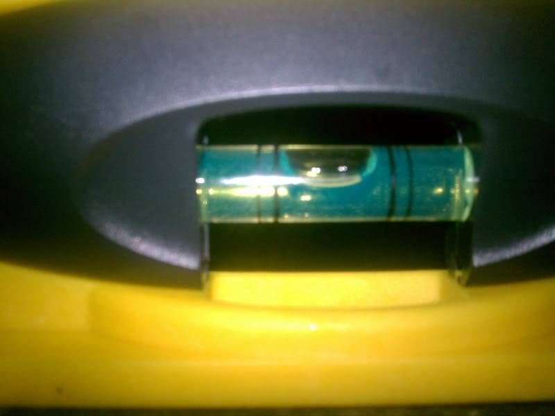
I measured the frame to the ground as follows:
The bottom of the rear frame at the front master gauge hole on the passenger side is 5 5/8" off the ground on the driver's side, and 5 3/4" to 5 7/8" to passenger side (the difference could be human error).
The front of the front subframe is 10 5/8 off the ground on the passenger side, and about that on the driver's side.
The alignment holes seem to be dead on just by eyeballing it and sticking my pinky in there.
It looks like the frame is bent or warped (possibly due to a collision) thus making front gauge hole not a reliable (is it datum?) point. So I went by one of the holes in the frame, and just hung a string with the equivalent of a plumb bob from one of the other holes in the frame. Those were the front of the subframe data points, or point "F".
The rear subframe, or the middle of the car was measured with a bent metal hanger to try to get the middle of the hole as close as possible. That is the middle data point, or point "M"
The rear frame rail was measured in the center of the master gauge hole in the front bottom of frame rail. They is my rear data point, or point "R".
In these measurements, "P" will connote passenger, "D" driver sides.
Measurements are as follows:
RP to MD = 79 5/8
RD to MP = 79 13/16
MP to FD = 50 1/2
MD to FP = 50 5/8
RD to MD = 69 5/8
RP to MP = 69 7/16
MP to MD = 44 3/4
FP to FD = 38 5/16
MP to FD = 28 7/8
MD to FP = 29 1/16
So basically, the lines from the master gauge hole of the rear frame to the opposite center of the master gauge hole outboard of the firewall body mount are 3/16" different. Is that too much?
It appears that the front subframe isn't 100% square - the lines from the master gauge hole to the front of the frame are 1/8" different. Is that OK?
Strangely, the lines from the rear frame master gauge hole to the sub frame master gauge hole out board of the body mount on the same side are about 3/8" different, and the same for the subframe master gauge to the front. Is that a problem?
What about the differences in ride heights?
I tried my best to measure, but it is extremely difficult to get it 100% perfect. These numbers are best estimates, but they look decent.
This was done with the suspension fully loaded, and the car on the ground. Is my frame OK?
10-30-2011 #16
Registered User
- Join Date
- Aug 2008
- Posts
- 59
I'm getting my SC&C stage II plus kit Monday and will install it next weekend.
I will measur from the ball joints at that time.
10-30-2011 #17
Registered User
- Join Date
- Oct 2009
- Location
- New Derry, PA
- Posts
- 1,265
If you are measuring between a hole in the rear tub (subframe) and the detachable front stub, you have a LOT of manufacturing tolerance going on there. It's possible that the passenger's side was hit in the rear (shorter measurement RP to MP), but more likely the stub just isn't bolted on square. The real way to tell that would be to drop the stub and measure from the rear datum holes to the bolt holes where the stub attaches. If those are off, you've got a problem...
I've seen how the factory uses those gauge holes... They shine a laser (or pinpoint light source) "X" at the hole. If the X isn't visible on the surface of the frame, off she goes to paint! Their tolerance is the entire size of the hole! Looking at it that way, yours might be just fine...
Ray Kaufman - Wyotech Chassis Fab and High Performance Instructor. Words of Wisdom from an old master... at Asylum Custom Interiors website
10-30-2011 #18
Registered User
- Join Date
- Aug 2008
- Posts
- 59
RP to MP is off by 3/16". I really don't want to drop the stub. It's all bolted together and drives fine. What is the worst that could happen if I just go get a thrust alignment and then weld in the SFCs? Originally Posted by exwestracer
10-30-2011 #19
Registered User
- Join Date
- Oct 2009
- Location
- New Derry, PA
- Posts
- 1,265
Sorry, just realized "MP" was on the tub, not the stub...
You answered your own question...it drives fine. Once the subframe connectors are welded in, it will still drive fine.
Ray Kaufman - Wyotech Chassis Fab and High Performance Instructor. Words of Wisdom from an old master... at Asylum Custom Interiors website
10-31-2011 #20
Full Blown G-Machiner
- Join Date
- Oct 2008
- Location
- Santa Fe Springs, CA
- Posts
- 625
Rp0029 – There are some good tips here. In a perfect world you’re better off making sure the frame is aligned before welding in subframe connectors. In an imperfect world you can weld them in as well as you’re sure the frame and body bushings are in good shape and the car takes a good 4-wheel alignment.
Originally Posted by rp0029
 Hotchkis Sport SuspensionToll Free: 877-466-7655

 Reply With Quote