


Results 21 to 40 of 112
Thread: 1st Gen Camaro Steering Arms
-
01-13-2017 #21
 Registered User
- Join Date
- Nov 2014
- Posts
- 39
 Ok, let us know, Mason. When you say bump steer corrected, is for like the common 2" drop?
 Originally Posted by Baxtek Fab

-
01-13-2017 #22
Registered User
- Join Date
- Jan 2017
- Location
- Palm Coast, FL
- Posts
- 44
yes the newer style 2" dropped spindles have a second set of holes to raise the steering arm to take away the bump steer issue. I have not checked to see how accurate it is but from a quick glance it looks way better than factory.
01-13-2017 #23 -Moderator-
- Join Date
- Apr 2001
- Location
- Central CA USA
- Posts
- 6,114
You can't just raise the steering arm on the spindle only. It will cause terminal bumpsteer on a drop spindle, the lower holes are for the steering arm, the upper holes are for the caliper mounting. With stock center link, you need the outer tie rod end to be LOWER than stock by more than 1/2". The taller you make the spindle, the lower the outer tie rod end needs to be.
Last edited by David Pozzi; 01-13-2017 at 04:00 PM.
David Pozzi http://www.pozziracing.com67 Camaro RS that will be faster than anything Mary owns.
01-13-2017 #24
Registered User
- Join Date
- Nov 2014
- Posts
- 39
I guess I misunderstood what Mason meant by 'bumpsteer corrected' and I didn't make myself clear. I wasn't referring to a 2" drop spindle, but I didnt say that either, my apologies. On my 67 I'm running the stock spindle with a 1/2" taller upper ball joint, and 2" drop springs. In my situation, I imagine the stock style z/28 arm would be best. I assumed (my fault, sorry) that when it was stated "bumpsteer corrected" he meant that the steering arm tie rod location would be moved similar to a stock arm that had been heated and bent to correct bumpsteer. I misunderstood, but I'm still interested in the shorter z/28 style arm, nevertheless. When you get these going, please contact me. Originally Posted by David Pozzi
01-14-2017 #25
Registered User
- Join Date
- Jan 2017
- Location
- Palm Coast, FL
- Posts
- 44
After your reply I put the car up on my 4 post lift to take a better look at what you were referring to. I see a hand full of issues that at a quick glance I did not pick up. It really needs a combination of the arms and center link dimensions adjusted to make it right. Thank you David for pointing it out!
Mason
01-14-2017 #26 Registered User
- Join Date
- Nov 2008
- Location
- Lawrenceburg, TN
- Posts
- 4,098
hello David thanks for jumping in Originally Posted by David Pozzi
01-14-2017 #27
Registered User
- Join Date
- Nov 2008
- Location
- Lawrenceburg, TN
- Posts
- 4,098
I have a new centerlink designed to fix the pivot points along with a beefer Tall dropped spindle ...its still in testing on a 69 project car im building Originally Posted by Baxtek Fab
01-14-2017 #28
Registered User
- Join Date
- Nov 2008
- Location
- Lawrenceburg, TN
- Posts
- 4,098
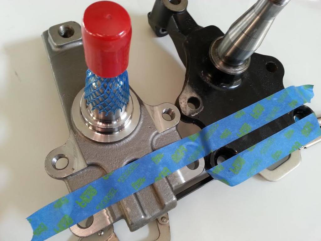
they look like Heidts spindles but there much taller and have a cool "S" cast into the backside that might stand for Suspension Geek...just saying.....working with a different steering arm location to allow for rim clearances
02-09-2017 #29
Registered User
- Join Date
- Jan 2014
- Posts
- 119
I'm in... tell me where my money goes....
Here's a link to play with some dimensions that will help you nail down the locations.
http://www.racingaspirations.com/apps/
02-09-2017 #30
Registered User
- Join Date
- May 2015
- Posts
- 255
Any updates on this topic?
02-13-2017 #31
Registered User
- Join Date
- Jan 2017
- Location
- Palm Coast, FL
- Posts
- 44
Finally got all of my parts in, rims tires, spindles, tubular upper and lower control arms. Hoping in the next couple days going to try and assemble one side and check for bump steer etc... I will update once I get mocked up and testing.
02-14-2017 #32
Registered User
- Join Date
- Nov 2008
- Location
- Lawrenceburg, TN
- Posts
- 4,098
Originally Posted by Baxtek Fab
cool....pictures to....lots of pictures
02-17-2017 #33
Registered User
- Join Date
- Jan 2017
- Location
- Palm Coast, FL
- Posts
- 44
I am hoping the photos get uploaded right>
02-17-2017 #34
Registered User
- Join Date
- Jan 2017
- Location
- Palm Coast, FL
- Posts
- 44
A little about the project. It is a 1967 Camaro that has seen 49 years of abuse and neglect. It started out as a simple full wiring of the entire car and installing a new 383 motor and a Tremec 5 speed. It then snow balled into a mild Pro-Touring combo with new rims/tires, front /rear sway bars and then new front and rear suspension etc... The front suspension uses Speedway Motors tubular upper and lower control arms, 2" dropped spindles, Wilwood 12.19 rotor with 4 piston clipers, QA1 single adjustable coilover shock conversion and ADDCO 1.25 sway bar. The Rims are Billet Specialty Street Lites with the black center 17x8 fronts 5.5" BS 245/45-17 and 17x9.5 rears with 6" BS 285/40-17. The rear suspension is simple but should be effective for this combo. It uses 2" dropped leaf springs, QA1 single adjustable shocks, ADDCO 1" sway bar and fully rebuilt rear with a new Auburn Gear Diff, 3.73 gears and Wilwood 11" rotor with 4 piston calipers. The interior has update AutoMeter gauges and Procar Rally 1000 bucket seats.
02-17-2017 #35
Registered User
- Join Date
- May 2015
- Posts
- 255
Looking good!
Does the 2" drop spindles make the steering arms closer to the wheel?
I think 18" wheels will give you more clearance?
02-17-2017 #36
Registered User
- Join Date
- Jan 2017
- Location
- Palm Coast, FL
- Posts
- 44
Should not be any closer or further away than stock spindles. 18" rims will only give us another 1/2" of clearance. So I'm going to modify the stock Z28 arm that I have and raise it up about 2" to clear the rim and then my machinist will make me a set based on that modified arm. After that the center link will need to be addressed to compensate for the almost 2" rise in outer tie rod end. It will get hooked up to my bump steer gauge and correct the bump steer.
02-18-2017 #37
Registered User
- Join Date
- Jan 2014
- Posts
- 119
hmm... that sounds a lot like what the ridetech tru-turn already does. Is there any way to simply build new steering arms without raising them and building a new center link? Originally Posted by Baxtek Fab
I was considering moving the tie-rod point lower, but pulling it in towards the center, but extending it longer toward the rear of the car, so as to get closer to the zero bumpsteer arc, keep the steering angle/turning radius, and obviously give clearance for wider rims.
Cons of the tru-turn: It seems some headers interfere at times. On some spindles the higher steering arm hits the lager brake calipers... also possible oil pan clearance due to extra bracket on center link.
02-18-2017 #38
Registered User
- Join Date
- Nov 2008
- Location
- Lawrenceburg, TN
- Posts
- 4,098
that helps bringing it in and moving it down....but you lose some akerman and the car changes turning radius......making it sluggish.... Originally Posted by ryanleiker
if you use a shorter arm....the easy way to reduce some bump is to rotate the top of the spindle rearward (increase caster) that rotates the steering arm downward
02-18-2017 #39 Registered User
- Join Date
- Sep 2004
- Posts
- 186
What dropped spindles do you have? Rather than modify the stock arm a full two inches, could you use an off the shelf arm? I thought ridetech used a Chevelle arm or something like that. Your situation is so similar to mine, except I have the 1 inch drop ATS AFX spindles (which also added some drop to the steering arm for their built in bump steer correction). I had actually thought about reversing the taper in the stock steering arm and using a bump steer kit (from the top) in combination with raised centerlink pivot points to mock up a solution. My thought was by flipping the tie rod topside of the stock arm, would I be able to put the pivot point in about the same location as a Ride Tech setup... I would rather just use the true turn, but I am not sure I have the clearance for that yet with my road race oil pan.
02-18-2017 #40
Registered User
- Join Date
- Jan 2017
- Location
- Palm Coast, FL
- Posts
- 44
Your setup seems similar but is different. I wish there was a simple fix to everything but it does not seem like a single steering arm will fix everyones problem. I have some photos of what I got accomplished today. I created a jig that keeps the steering arm pieces inline with the factory specs to not change the Ackerman etc... I modified a Standard arm and a Z28 arm. The standard arm was raised first 1.5 then at 2" and it did not work out. Modified the Z28 arm and raised it 1.5" and it just clears a factory style outer tie rod end. I have a few parts being delivered next week that will hopefully allow me to lower it a solid 1/4" maybe more. TBT

 Reply With Quote