


Results 61 to 80 of 86
-
01-05-2016 #61

 Registered User
- Join Date
- Nov 2008
- Location
- Lawrenceburg, TN
- Posts
- 4,098

great stuff! dig the topics and tuning strategy, so i pose extra questions...How much SW must you shave off to equivocate it to shaving off 1 pound of USW or vice versa, at what poundage number do you start to feel the effects? 200, 300 pounds...
and what does it take to over come SW poundage
what I used to see was most guys dropped a 100 pounds off the car and added power to there ride to help, but the next level is now drop 300-400 pounds and add power
-
01-05-2016 #62
Registered User
- Join Date
- Oct 2011
- Location
- Camarillo, CA
- Posts
- 78
When can I sign up for your suspension class?
01-05-2016 #63 Registered User
- Join Date
- Aug 2010
- Location
- now In Dandridge, Tn.
- Posts
- 1,301
As more and more guys cut weight, and for some that have - in the 300 - 400 range, shock tuning will get more and more difficult due to the USW %. Most weight is being cut from the body/chassis/interior. All Sprung Weight. This may help in a drag race, but not so much around corners an really not so much on un-even surfaces. Originally Posted by Rod

Put the weight into three groups and cut accordingly. - OK four (I decided to cut one in two)
1) Rotating and Un-Sprung. This is the worst. All of this weight moves to upset the car, and all of it has to accelerate and decelerate. Wheels, tires, hubs, rotors, axles, gears...... This is one of the hardest areas to cut weight, and it can get expensive, but the pay-offs are big.
2) Un-Sprung weight. 2nd worst and equally hard to cut. With the rotating section removed, there isn't a lot left. Spindles, axle housing, calipers, control arms, shocks and springs.... ever wonder why Afco makes "Lightweight" coil springs? Again, this is a tough place to cut.
3) Rotating and Sprung. Get you wallet out for this one. balancer, crank, rods, pistons, flywheel, clutch, driveshaft. This won't be big in poundage, but it will pay off in performance - acceleration.
4) Sprung weight. the easy one. This is everything else. Body, interior, chassis....
Before you dismiss some of those as "not enough to worry about", think about the bracket racers that disconnect the alternator to win a race.
I try to think of the USW in %, not lbs. It helps me focus on the weight I should be concerned about most.
01-06-2016 #64 Registered User
- Join Date
- Dec 2006
- Location
- Out of the Burbs of Detroit to SoCal, then onto my ancestral homeland, the woods of Cascadia
- Posts
- 1,753
Think you need to try the math again 476/1400, not 476/924, for closer to 35% unsprung weight, but the rest is good Originally Posted by RobNoLimit
Greg Fast
(yes, the last name is spelled correctly)
1970 Camaro RS Clone
1984 el Camino
1973 MGB vintage E/Prod race car
(Soon to be an SCCA H/Prod limited prep)
01-06-2016 #65
Registered User
- Join Date
- Aug 2010
- Location
- now In Dandridge, Tn.
- Posts
- 1,301
Well there is more than one way to skin a cat. That's what I heard anyway. When I compare Un-Sprung %, I do this based on the amount of Sprung weight above that corner. - Not the total weight (which would include the Un-Sprung weight). If you put a car on scales, and separate out the weight on the rear axle (LR and RR weights) this includes the Un-Sprung and Sprung weights to give you the total. But what I am interested in is the comparison, or relationship between the two, Sprung vs. Un-Sprung. in the example, 1400lbs was the total weight, including both SW and USW, so, I subtracted my estimated USW (476) from the total to get an estimated SW of 924 lbs. The relationship that I am interested in is the % match up (as a comparison and tuning number to scale with) between those two.
I have read of some using USW as it relates to TW but this doesn't make mush sense to me when it comes to shock and spring tuning. As it is the shock and spring that work between these two masses/forces. (USW vs. SW) - That's why I did it that way. - your results may vary.
01-06-2016 #66
Registered User
- Join Date
- Jun 2014
- Posts
- 160
I recently inquired about a rear set up for my truck and got some great feedback. this last bit of information explained why those things would be of great benefit. as usual good stuff Rob.
01-09-2016 #67
Registered User
- Join Date
- Aug 2011
- Location
- Missouri
- Posts
- 19
Great read Rob. Thanks for sharing your vast amount of knowledge!
Scott
02-09-2016 #68
Registered User
- Join Date
- Oct 2012
- Posts
- 434
I love this thread and have a question. I am designing a full frame/suspension for my 85 C10 and was curious about frame width. Is there a benefit to having a wider frame vs a narrower frame? Or is it best to follow stock width?
02-10-2016 #69 Registered User
- Join Date
- May 2012
- Location
- Boston, MA area
- Posts
- 59
Rob,
Can you explain the same thing for independent suspension set up on the rear? I have been looking at using a C6 based suspension and drivetrain. I know this will save some weight on the SW and pending on the parts it may over all, by spreading the weight of the motor and transaxle or I should say help to balance the F/R weight, along with possibly lowering the height of the weight as well.Building cars or any project must be fun first. If not it turns into a job.
We build cars for the fun and enjoyment of it, it is a family time things.
So if the fun stops, the build stops.
02-10-2016 #70 Starting The Transformation
- Join Date
- Feb 2010
- Location
- El Segundo, CA
- Posts
- 268
Are you asking about the width of the frame rails? Or the width of the frame from rail-to-rail? Gustave Originally Posted by mitch_04
02-10-2016 #71
Registered User
- Join Date
- Oct 2012
- Posts
- 434
Should have specified, the distance between frame rails. Is a wider frame or a narrower frame (not frame rail) preferred, and why?
02-11-2016 #72
Registered User
- Join Date
- Aug 2010
- Location
- now In Dandridge, Tn.
- Posts
- 1,301
Good question. Here is a simple engineering test that we can all understand and remember. I won't drag in all of the math, just an easy demonstration. Think of a chassis as a link between the front and rear suspension. Most forces will be in one of two main areas. 1) flex in the middle - support the chassis on both ends and apply force in the center. Any direction, up, down, sideways, ... and 2) Grab the chassis at each end and try to twist it. Got an image of that? great. Now, imagine the chassis as a link, or a tube for our discussion. Start with a 1 1/4" solid round bar, 10 feet long. Can you bend it? and/or twist it? I bet you could. Now, compare this to a 5" diameter tube with .120" wall thickness, 10 feet long. (Just so you know, these two links have appx the same weight, within 4%, so there is appx the same amount of metal in each). Can you bend it? a little, can you twist it? Not so much. Give that some thought. Originally Posted by mitch_04
The general rule is that 'larger' the dimensions you have - against the forces applied, the better off you will be. A 'wider' chassis resists 'side' forces more. A 'taller' chassis resists 'up' and 'down' forces more. A more 3-dimensional chassis resists 'twist' forces more. OK, this is a really over simplified look, but the concept is true. Yes, X-members, crossmembers, material thickness, gusseting....... all can help, and the overall design can be improved, but as to general width, there you go.
02-11-2016 #73
Registered User
- Join Date
- Aug 2010
- Location
- now In Dandridge, Tn.
- Posts
- 1,301
Disclaimer: I have very little knowledge with IRS suspensions - but I am rapidly learning. ** OK, so yes. The C6 IRS concept is a good one. The actual transmission is basically moved back to the rear axle, or just in front of it, for better weight balance. And, with an IRS, the differential and it's housing go from being 'un-sprung' weight, moving with the tires, to being 'sprung' weight, moving with the chassis. With my current Cobra project I have found the IRS to be lighter in total weight that a 9" would have been, with a lot less USW. So, over all, it's a win/win/win. Less USW, less total weight, and better weight balance. Originally Posted by Rebeca_Lynn
There may be a negative, and that's the width WMS/WMS (Wheel Mount Surface) The C6 IRS is like 64" wide. (don't quote me it was a guess) For F-100's we want about 60", and for C10's around 62". For a later (67 on up) you can make tis up with wheel offset, but for narrower builds, it's custom arms and half-shafts, and some other things. So measure it out first.
02-11-2016 #74
Registered User
- Join Date
- May 2012
- Location
- Boston, MA area
- Posts
- 59
Thanks Rob,
I guess it is time for my husband, son and me to sitdown and start doing so design work with Autocad and Solidworks. Get a couple basic ideas laid out and try to figure it out from there.
- - - Updated - - -
Thanks Rob,
I guess it is time for my husband, son and me to sitdown and start doing so design work with Autocad and Solidworks. Get a couple basic ideas laid out and try to figure it out from there.Building cars or any project must be fun first. If not it turns into a job.
We build cars for the fun and enjoyment of it, it is a family time things.
So if the fun stops, the build stops.
02-11-2016 #75 Registered User
- Join Date
- Oct 2010
- Location
- Mena, AR
- Posts
- 287
Well where have I been that I missed this thread entirely? Great info here Rob, and thanks for you and others sharing not only the theory of the design but the process to start the basic design. . Ok back to reading......
Chris
Chris
1967 ElCamino
2004 Chevy SSR (my sons)
1951 Chevy pickup(my sons)
1967 Elky https://www.pro-touring.com/showthre...587-Evil-Angel
1951 truck https://www.pro-touring.com/threads/...3-year-old-son
02-12-2016 #76
Starting The Transformation
- Join Date
- Feb 2010
- Location
- El Segundo, CA
- Posts
- 268
Having given this subject a lot of thought over the years, there is one more mode of frame deflection besides bending and torsion. I call it "shear" for lack of a better name. This would be where the left frame member moves forward while the right frame member moves backwards (or visa versa). Originally Posted by RobNoLimit
I find it interesting to look at early 60's Impalas on the Chassis Cam during Barrett Jackson auctions. They have what is termed an X-frame. Seen here:
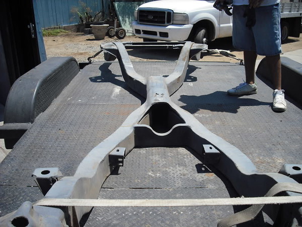
Such a frame would be good at resisting shear forces, ok at resisting bending forces and horrible at resisting torsional (twisting) forces. And since shear deflection is not as likely as bending and torsion, I would not really want an "X-frame" under my F100.
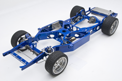
The best way to stiffen up a car or truck is to install a well thought out roll cage. With a car it is about the only thing you can do. But with trucks you can do a lot more to stiffen the frame without resorting to a cage. There is a lot of room under the floor and bed of a truck, allowing for a tall frame, which as Rob points out is a good way to stiffen said frame in bending and torsion. I reckon on my 1956 F100 there is a good 10-11 vertical inches available between the bottom of the cab and the lowest part of the truck. Hence perhaps the No Limit Big-10 frame (10 inches tall).
Gustave
02-13-2016 #77
Registered User
- Join Date
- Dec 2015
- Location
- Ruhr-Area, NRW, Germany
- Posts
- 313

Not aiming to be the smart-ass here but i think the important difference between the Big-10 chassis and a normal truck frame is the X-shaped structure in the center, that links all of the points that have some kind of force transmitted into them to eachother.
Without that, even an 11" tall lader type frame will twist like a fish...
I want to build a bolt-in X-structure like that for my projects frame.
For cars there's a lot more you can do than a roll cage (increasing the number of pinch welds, stitch-welding frame structures, adding reinforcement panels to link structures together, etc.)
02-13-2016 #78
Starting The Transformation
- Join Date
- Feb 2010
- Location
- El Segundo, CA
- Posts
- 268
An X-frame inside a wider rectangular section (Big-10) is different than an X-frame on it's own (like the Impala I showed). Generally you want to load tubes (or frame sections) in tension or compression, not in bending, in order to get the biggest increase in torsional stiffness. Also, I hope that I did not convey the impression that a truck can be stiffer than a car. With a truck the body panels do nothing for you in terms of stiffness. In a car, the existence of a roof make it stiffer than a truck, with or without a roll cage. But if you use the space available to you underneath a truck (which a car cannot do) then you can definitely improve stiffness a lot. Rob's Big-10 frame is the only one on the market that takes advantage of this possiblity. Originally Posted by kingcrunch
In a previous life a was pretty into BMW M3's (E30 and E46) and I am aware that you can seam weld an entire unibody. But that is going to be an incremental thing (it's easy, cheap, does not add weight, so why not seam weld the body?). However, the biggest improvement in bending and torsional rigidity for a car will come from adding a roll cage.
As Rob mentioned, the ideal for torsional rigidity is a cylindrical tube (we're both engineers so this was taught us in college). Next up would be a square (or rectangular) tube. A truck frame can be thought of as a rectangular tube. At the risk of getting "wonky" here's a formula for the polar moment of inertia for a rectangular hollow section rectangular tube:

The polar moment of inertia dictates how stiff a tube will be in torsion about it's axis. If you look at the formula, you can see that the two relevant parameters are the height and width of the rectangular tube. Thus by analogy, for a truck frame, if you make it wider, taller, or both, you will make it stiffer. That is the point I was trying to make.
And for bending, making a truck frame taller is also a big improvement. Conclusion: if one is designing and building a truck frame with performance intentions, then if you do not make it as tall as possible, you are leaving meat on the table (so to speak).
Gustave
02-20-2016 #79
Registered User
- Join Date
- Oct 2012
- Posts
- 434
Alright, so I have started to draw out my frame design. Some of my roadblocks thus far are...
1. How do you know when to narrow the front to clear the tires, and how far?
2. How close can the frame be to the tires in the rear without worrying about rubbing when one side is fully compressed/extended?
I am in Kuwait, a few thousand miles from my spindles and such so I am not able to get measurements to draw them out. If anyone has the essential measurements for an 85 C10 drop Spindle I would really appreciate it. I have suspension Analyzer and would like to draw something up before I go home.
02-21-2016 #80
Registered User
- Join Date
- Dec 2010
- Posts
- 708
This is a great thread, and I'm not even building a truck. For clarity on what the guys are saying above about a "tall" frame, research the design of a C4 Corvette's frame. It's very tall, well through the front and rear suspension mounting points. (There's also a safety thing here, in that you sit inside of it, kind of like a tub or a coffin.) Then, when it's not so tall in the front, it gets fat . . .
So apparently, in truck (or car) frames, gymnastics, and boat building, we must always think of beam . . .

 Reply With Quote


