

Results 41 to 60 of 76
Thread: 1971 Pontiac Lemans Convertible
-
02-16-2013 #41
 Registered User
- Join Date
- Nov 2011
- Location
- Springfield, OH
- Posts
- 58
Gas Tank, Gas Line, Evap System
As mentioned in a previous post I have figured out a way to use the gas tank from the 2004 GTO donor in my Lemans convertible.
The gas tank in the GTO is installed over the rear axle between the rear seat and the trunk. It wouldn't fit in this area in the Lemans since the convertible top has to fold into that area. I placed the gas tank on the forward part of the trunk floor, it ends up fitting pretty well under the body panel between the top and the trunk opening. My design somewhat resembles how the tank was installed in the GTO.
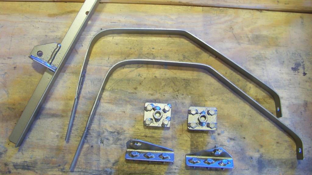
The first picture shows the hardware I fabricated to hold the tank in the car.
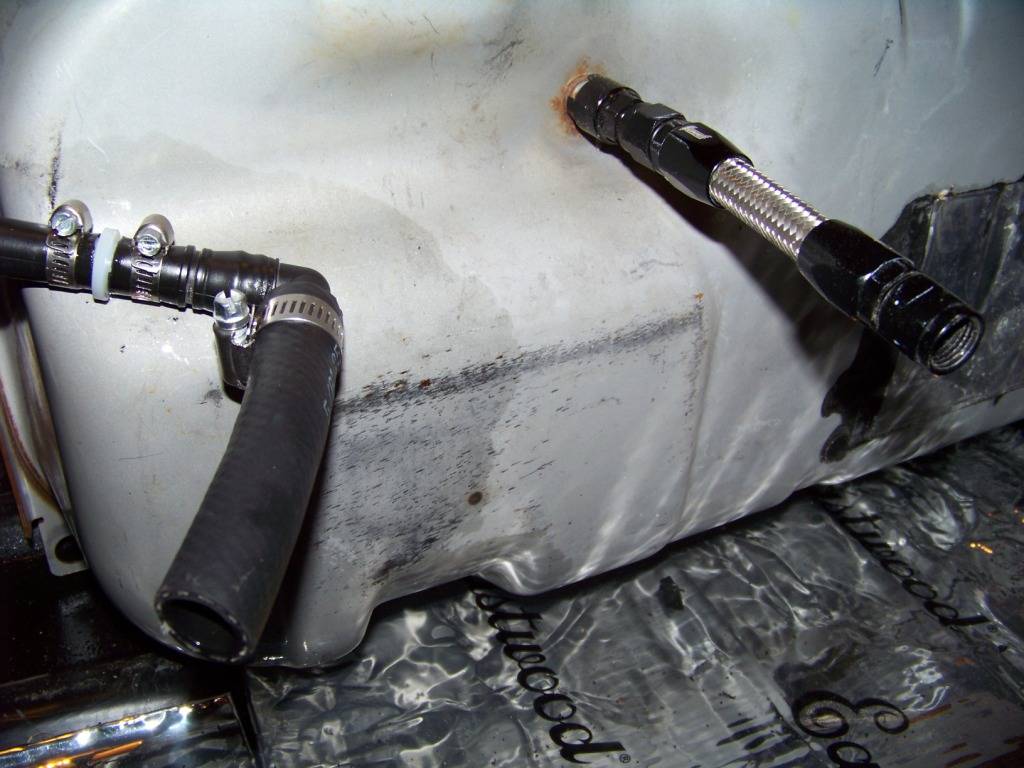
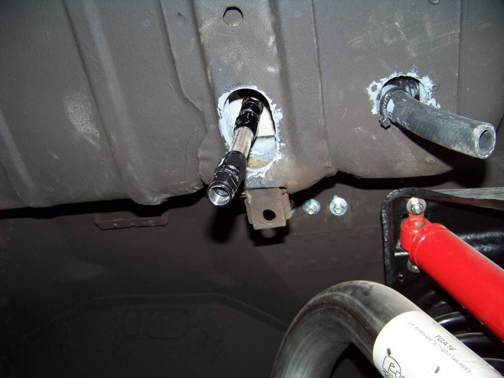
The GTO's fuel and vapor connections are on the bottom of the tank, I drilled large holes in the trunk floor to accommodate those and installed short sections of hose to feed through the floor holes, the pictures below show this. The first picture shows the tank with the black plastic shroud removed. These connections are inaccessible when the tank is installed so I had to provide secondary connections under the floor, similar to what is done with electrical pigtails. The fuel feed connection on the bottom of the tank is the same type and size as the one on the fuel rail. I used a Russell Fuel Rail to -6AN adapter, part number RUS-644123 for that and then made a small -6AN hose as shown. The vapor hose is 5/8" ID fuel rated hose I ordered from McMaster. I installed sound deadener material on the trunk floor before the tank went in. The second picture is taken from underneath and shows these hose connections.
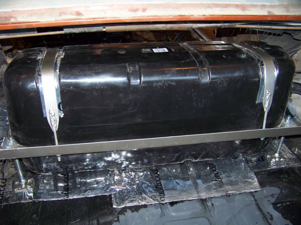
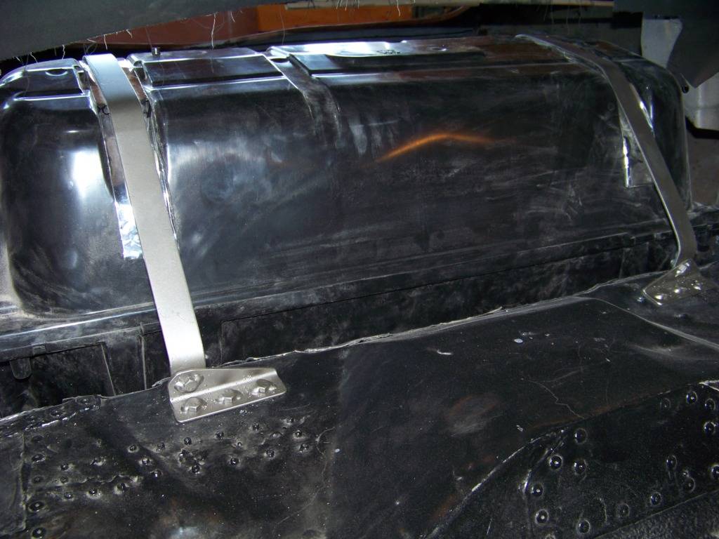
This next picture shows the installation of the tank in the forward part of the trunk. I put sound deadener material on top of the tank where the straps go to protect the plastic shroud.
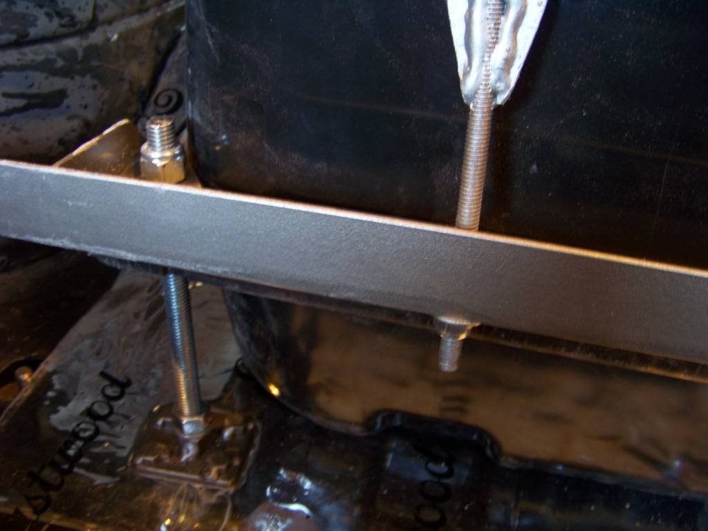
A close up of the trunk side hardware is shown below. The 1/2" threaded rods go through pre-existing holes in the aft corners on the tank, then the bottom of the threaded rods go into the plates I made on the bottom of the floor. These plates have a 1/2" nut tack welded to the middle of the plate and four 5/16" x 1" bolts tack welded to the corners. This way I could tighten the nuts underneath without having to hold the bolts above the floor. The straps are just 1/8" x 1 1/4" steel straps with 5/16 threaded rod welded into slots on one end. The rods then go through holes in the horizontal angle. The horizontal angle is attached to the aft corners of the tank with the threaded rod. The angle will also support the forward carpeted wall of the tank when I get to that point.
The picture below shows the installation on the forward part of the tank, this is looking from the rear seat area. The tank straps are bolted to brackets that are installed into the floor. The brackets have four 5/16" x 1" bolts tacked onto them, three go through the floor and are bolted underneath, the remaining one holds the end of the strap.
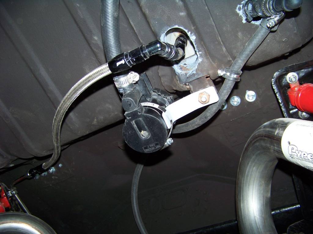
The next picture shows the installation of the EVAP cannister vent solenoid, this is a view looking up at the bottom of the trunk floor. I made the simple bracket shown below that is bolted to the former forward gas tank strap support in the Lemans, a hose clamp holds the solenoid to the bracket. This picture also shows the AN hose I made to connect the pigtail hose on the tank to the fuel rail that runs along the frame rail.
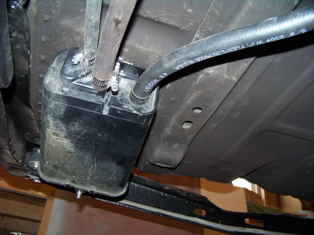
The following picture shows the installation of the EVAP canister which I bolted to the bottom of the trunk floor just inside the frame rail forward of the last frame crossmember.
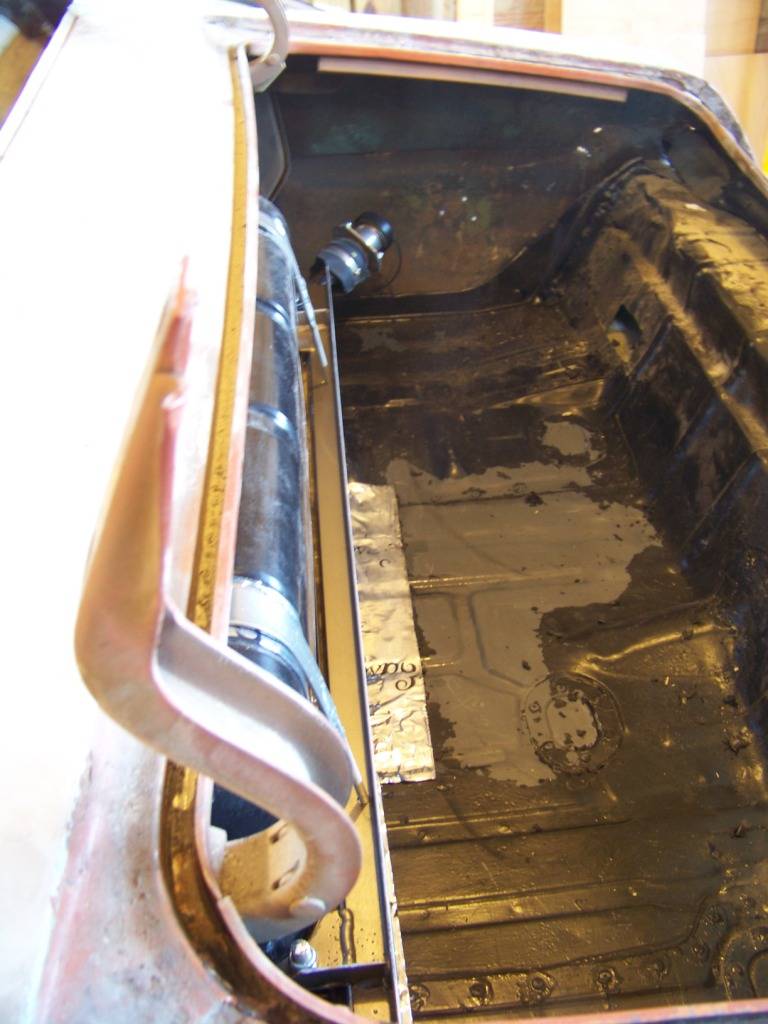
The view below is from the side of the car looking into the trunk, it shows how much the gas tank protrudes into the trunk area; which isn't too bad. I did loose some trunk area, but as I said before my plan is to install the GTO donor spare tire under the trunk floor so I think I still have a nice usable trunk space.
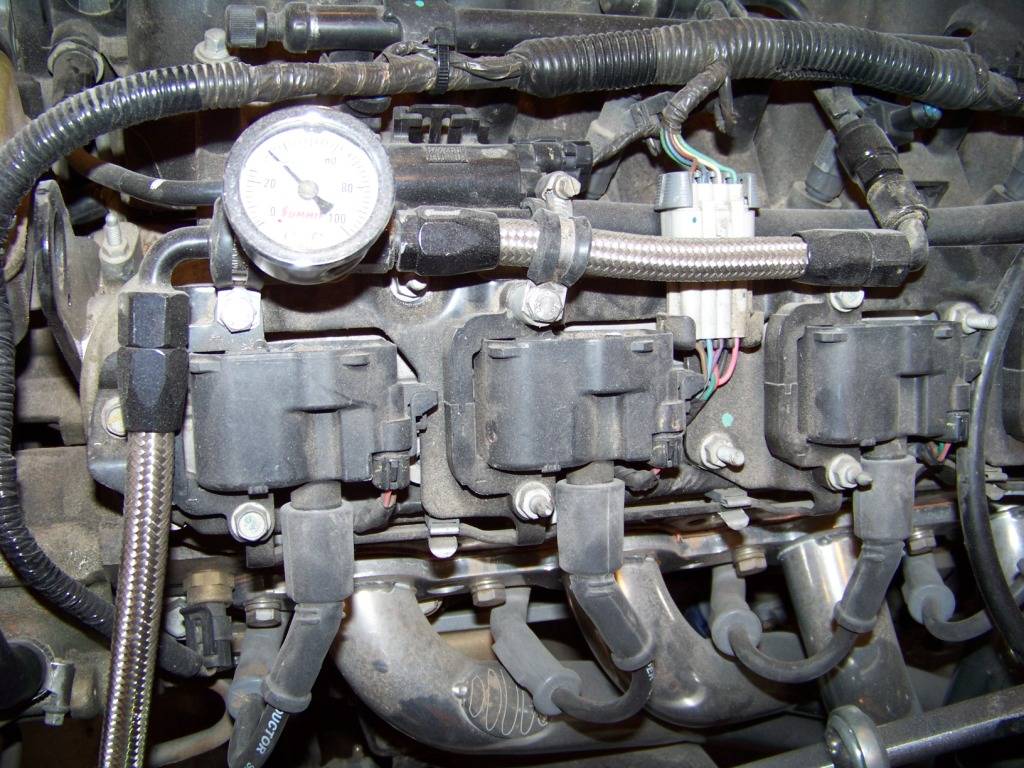
This final picture shows the fuel line installation on the engine. I ran the standard a-body fuel line in stainless along the frame rail and installed tube compression to -6AN fittings at each end. At the engine side I ran some -6AN hoses as shown and also added a permanent fuel pressure gauge. In this view you can also see the vapor hose connection just underneath the coil electrical connector. This is just 3/8 fuel injection hose that runs along the passenger side frame rail to the evap canister.
I am very pleased with the way this has worked out. I used another major component from the GTO donor, didn't have to buy another gas tank, fuel pump and sender and figure out how to hook those up. Since these are the OEM components everything works as it was designed to including the fuel gauge.
-
02-16-2013 #42
 Registered User
- Join Date
- Jan 2008
- Location
- Houston, TX
- Posts
- 193

Shelby flip cap on the passenger quarter? It would be sweet. Keep up the great work.
Asa Walker
Houston, TX
-
02-19-2013 #43
Registered User
- Join Date
- Nov 2011
- Location
- Springfield, OH
- Posts
- 58
Air Cleaner
Back under the hood, a few more things to take care of. This post covers my air cleaner solution. I looked into different tubing and filters but I found the parts and filters get expensive in a hurry. So once again I looked at using what I took off the GTO donor.
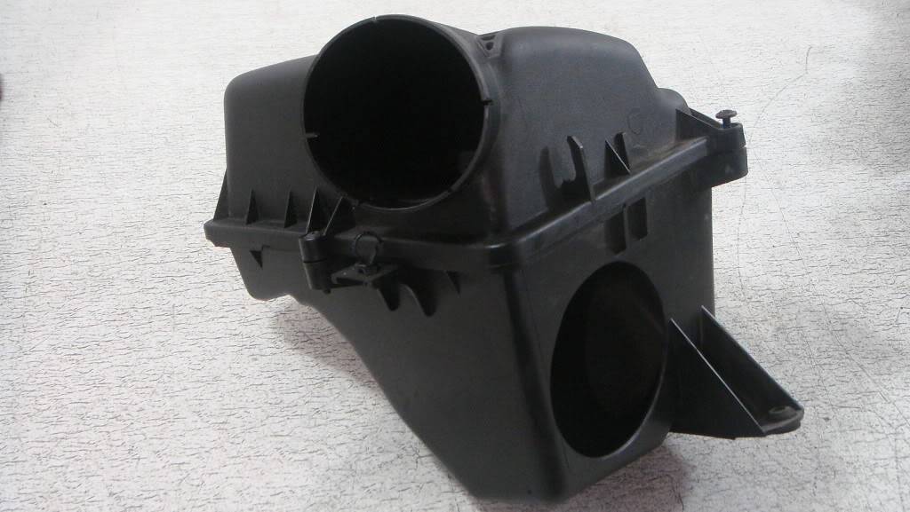
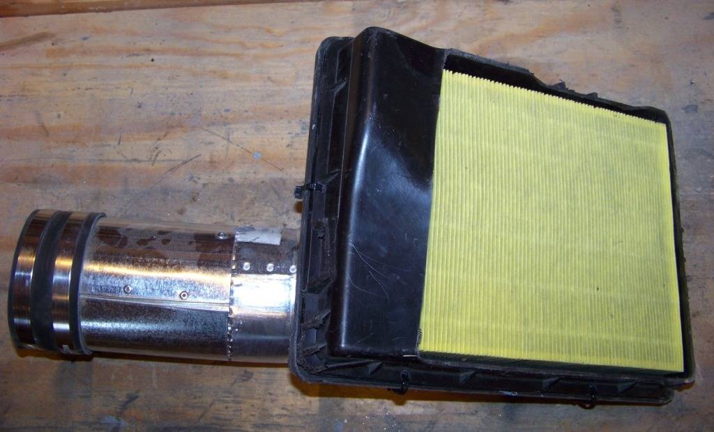
The picture below shows the air cleaner assembly from the GTO. Try as I might, I couldnt fit this large shape anywhere under the hood of the Lemans.
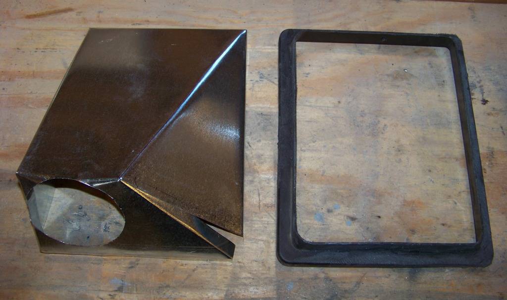
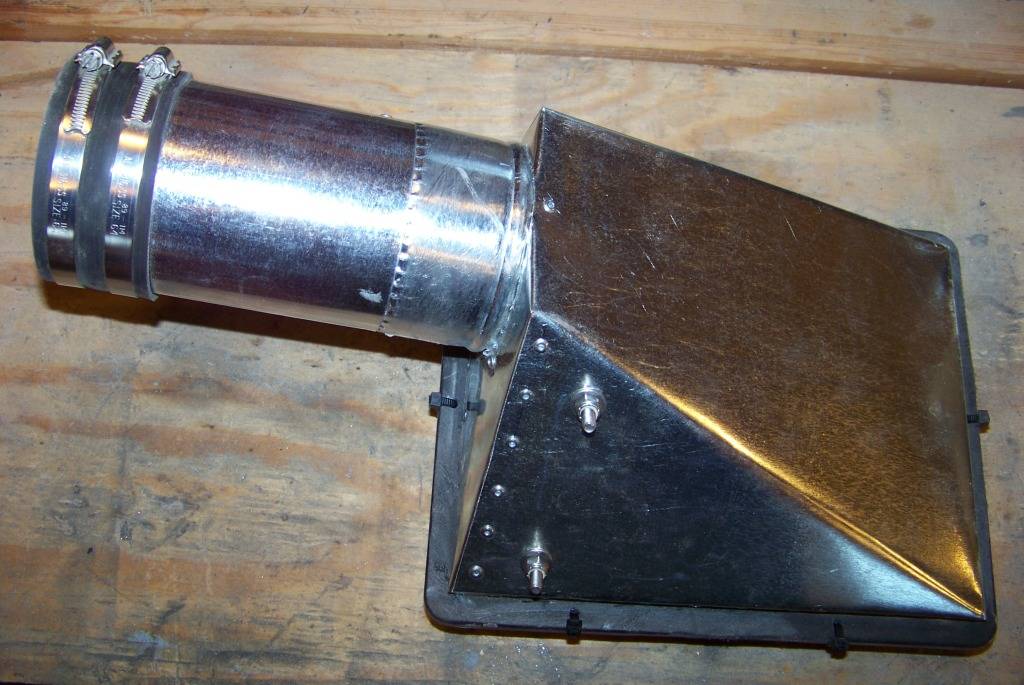
So after much fussing and cutting here is what I came up with. I chose the area under the coolant recovery tank between the core support and drivers inner fender for the air cleaner location. I cut down the GTO air cleaner assembly to just an upper and lower frame to hold the air cleaner element and made a new sheet metal top for it as shown below. This material is just the thin sheet metal that is sold for ductwork at Lowes. This picture shows the sheet metal top before I riveted it together and the top frame of the GTO air cleaner assembly after I cut the top portion off.
The two pictures below show the top and bottom of the completed air cleaner assembly. The sheet metal top was riveted together and to the top frame of the GTO air cleaner assembly. A 4 duct collar and 4 duct were also purchased at Lowes and attached to the sheet metal top as shown with rivets. The top and bottom frames are held together with zip ties, when I replace the filter I will just cut them off and then install new ones.
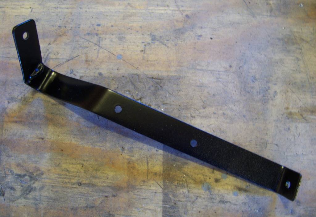
I made the bracket shown below to support the new air cleaner assembly:
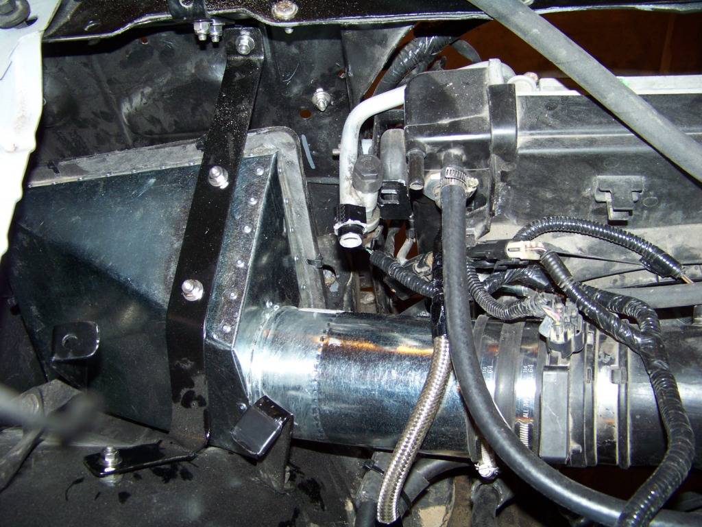
And finally this picture shows the completed air cleaner assembly installed in the Lemans. The air cleaner assembly just hangs below the bracket I made, all of this fits below the coolant recovery tank that is not installed here but was shown in the previous post on the cooling system. I got probably $20 into this, mostly for the duct parts.
-
02-19-2013 #44
 -Moderator/Sponsor-
- Join Date
- Apr 2001
- Location
- The City of Fountains
- Posts
- 16,117
Why is the gas tank in the trunk?
Andrew1970 GTO Version 3.0
1967 Cougar build
GM High-Tech Performance feature
My YouTube Channel Please Subscribe!
Instagram @dr__efi
I deliver what EFI promises.
Remote Holley EFI tuning.
Please get in touch if I can be of service.
"You were the gun, your voice was the trigger, your bravery was the barrel, your eyes were the bullets." ~ Her
-
02-20-2013 #45
Registered User
- Join Date
- Nov 2011
- Location
- Springfield, OH
- Posts
- 58
Andrew,
The gas tank is located in the forward part of the trunk area in the GTO donor, I installed it into the Lemans in a similar position and a similar way.
Phil
-
02-20-2013 #46
Registered User
- Join Date
- Feb 2012
- Location
- Ohio
- Posts
- 129
Yes its much cheaper to buy a wreck... And you get all the parts, your car looked restorable, I was the second buyer so my wreck was even cheaper. The guy before me just took the engine. Originally Posted by fsdproject

I decided against the abs also. The abs on the GTO isn't that hot but it would be interesting.
I was considering putting the gas tank in the trunk but I am not sure. My car wont have a back seat though(its a two seater soon).
I have the LS3(camaro), corvette C6 front suspension, Mustang GT500 rear end, 2004 GTO interior...
this was my fun time... sawzalled the roof and stuff, cut the floor out etc...
-
02-20-2013 #47
Registered User
- Join Date
- Nov 2011
- Location
- Springfield, OH
- Posts
- 58
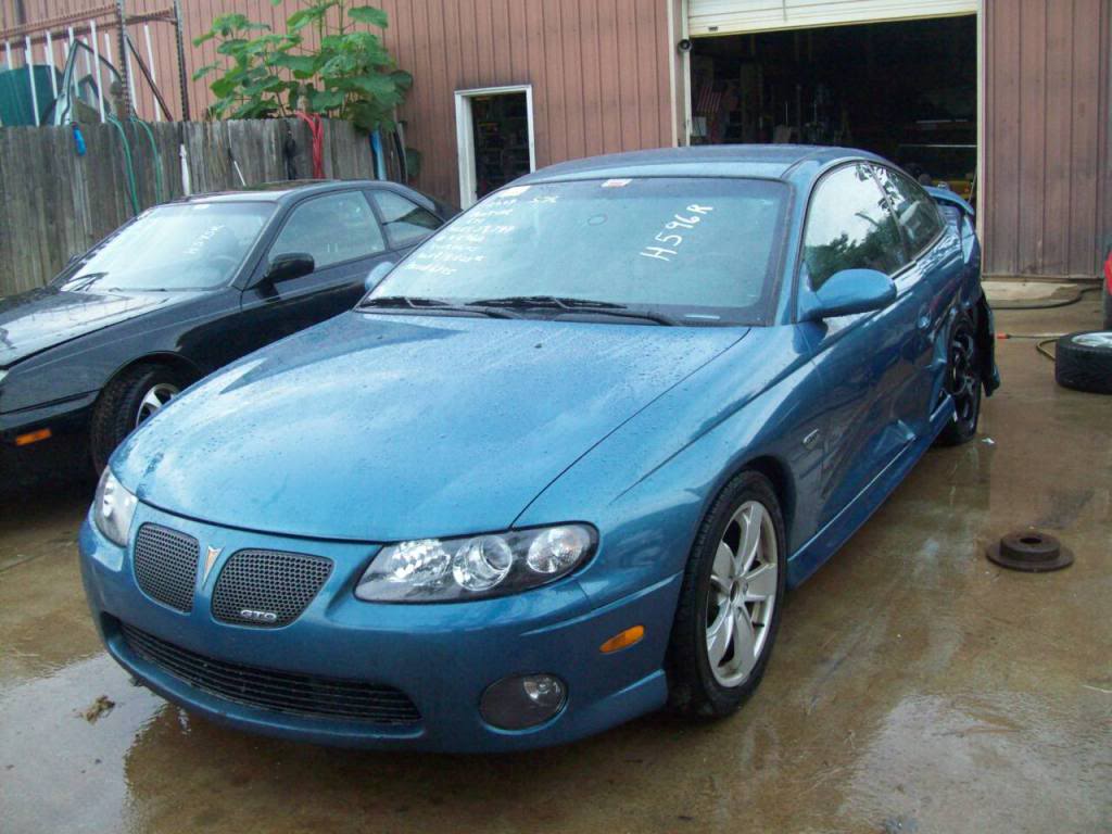
mikes2nd:
Using the donor car is working out even better than I hoped it would. I would highly recommend it to anyone doing a swap to the degree that I am. The GTO that I bought was hit pretty hard on the side, the driver's door is toast and there is some buckling on the inside. The driver's side rear tire is canted inward so something happened there also. I am appalled how easily cars are totaled these days, but I guess that works to our advantage supplying us with parts.
My GTO is down to glass, suspension and brakes. I have cut some sheet metal out of it too so I assume the shell is probably not worth anything beyond scrap value. I will probably be taking the sawzall to it when the weather gets a little warmer.
Do you have a build thread? I searched and couldn't find one, would love to see more of your car.
Phil
-
02-21-2013 #48
Registered User
- Join Date
- Feb 2012
- Location
- Ohio
- Posts
- 129
only thing left worth anything on these cars is probably the rear axles and the diff.
That sells pretty quick. I still have the rear bumper in my garage... and tons of other parts that are actually useful.
There are TONS of GTO parts on ebay and at the scrap yards. I think they sold more of these cars than I thought.
I have cut off the front and am cutting off the rear to narrow it/setup for the mustang axle.
I am also using the GTO tunnel in the car. The firewall is moving back like 6 inches! That is killing my back seats pretty much, I could almost fit them in there but there no point. It will be maybe a sideways temporary seat(dangerous!) and storage area. Maybe change the tray package for one rear center seat.
I am documenting the project, I just need to get everything together.
I am not doing such a "traditional" swap. They did a swap on TV but that was a body swap by west coast customs for their 1969 rockstar car(and it looks pretty sloppy), hack and weld, hack and weld, slap black frame paint over it....
http://www.355nation.net/forum/image...-magazine.html
you can see the welding on it is pretty brutal..
http://www.ls1gto.com/forums/showthr...=305392&page=2
http://www.youtube.com/watch?v=mwrq8MZtp0w
http://www.ls1gto.com/forums/showthread.php?t=360599
Here is a link to another, they have some good info for you. I don't think its horrible work, but I would have at least sand blasted the body before I started this one... And I am not going to weld the body to the frame... don't know whats up with that.
http://www.corbettsauto.com/pictures/1969_GTO/
http://www.corbettsauto.com/1969_pon...o-assembly.htm
-
02-21-2013 #49
Registered User
- Join Date
- Nov 2011
- Location
- Springfield, OH
- Posts
- 58
Windshield Washer Tank
This post covers the fabrication and installation of the washer tank. Not the most exciting thing in the world, but its the one of the last things to be installed under the hood and that area is DONE!
Following with my theme I used existing parts as much as possible. The washer tank from the GTO donor was an odd shape which I couldnt get to work. I used parts from that tank along with the tank from the Lemans to make my own combination. The picture below shows the tank from the Lemans and the filler neck and washer pump from the GTO donor.
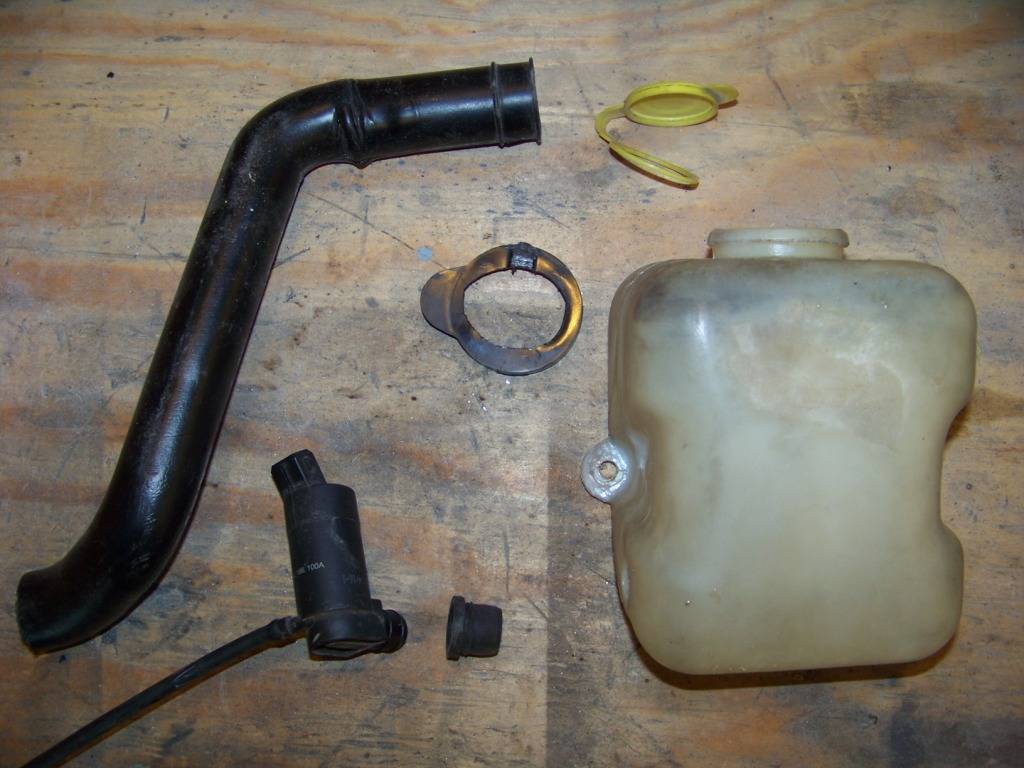
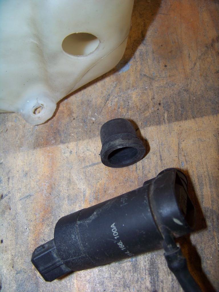
The washer pump from the GTO fits into a hole in the tank with a rubber grommet/filter screen. I just drilled the appropriate sized hole in the side of the Lemans tank and pushed the grommet and pump in.
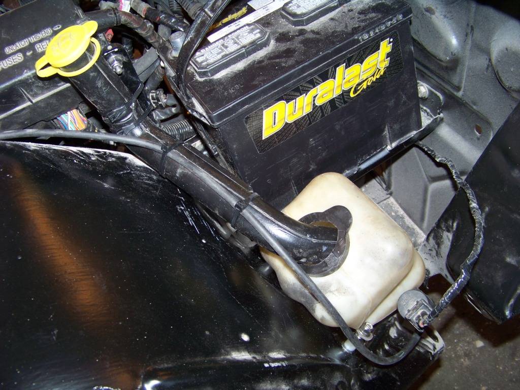
The only area left under the hood was under and to the outside of the battery on the passenger side. This view shows that area with the passenger fender removed. I had to lengthen the harness slightly to get the connector to reach.
I removed the squirter nozzles from the GTOs hood and hope to install those into the Lemans hood.
-
02-22-2013 #50
Registered User
- Join Date
- Nov 2011
- Location
- Springfield, OH
- Posts
- 58
mikes2nd:
I have noticed the number of GTO parts on ebay and craigslist, I wonder if that's where most of them have ended up; you don't see them on the road that much.
I ended up installing part of the GTO firewall into my Lemans about 4 inches behind the Lemans firewall. I hope to start documenting that part of the build soon. I did have to cut off the portion of the dash that had the defroster vents, but I hope to work those back into the vinyl part of the dash. I am not sure yet how much back seat space I will have but it probably won't be much, especially in the footwell area. I don't plan on having back seat passengers that often but when I do I will just move the front seats up a bit.
I have seen the Rockstar GTO, thanks for all the links on that. I was interesting to read all the background info on that build and what goes on at that shop. I took my kids on vacation to LA last year for spring break and we visited that shop and Chip Foose's shop. I do wonder sometimes if the way they did it would have been a better way to go, but I don't have that level of fabrication skills. I don't know if I would feel comfortable driving a car that was put together in such a way, I wonder about the structural integrity.
I had also already seen the GTO build at Corbetts Auto, but I looked at it again more carefully. They must have really compressed the top of the dash to get it to work like that. At lot of their pictures sure look familiar, that build closely resembles what I am doing.
Thanks again for posting, looking forward to reading about your build.
Phil
-
02-25-2013 #51
Registered User
- Join Date
- Nov 2011
- Location
- Springfield, OH
- Posts
- 58
Dashboard
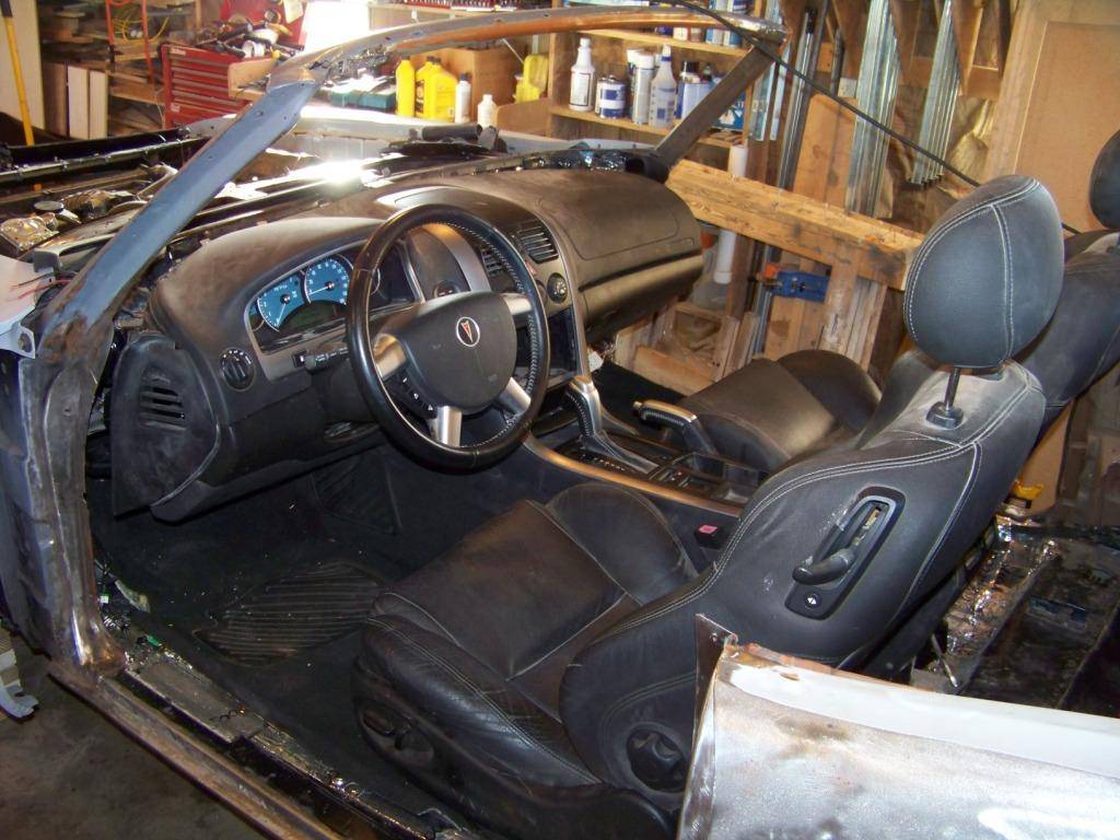
The next few posts will partially cover how I am getting the interior from the GTO donor into the Lemans. This first post will talk about the installation of the dashboard.
The dashboard is a geometric and ergonomic challenge. I am trying to incorporate mechanical parts and design from a car built in 2004 into a car built in 1971. The philosophy behind the designs of the dash area was quite a bit different between these two time periods. Some compromises have to be done to merge the two together. The main issue is that the windshield on newer cars such as the 2004 GTO are much more steeply angled than on the 1971 Lemans. This means the top of the dash is deeper in length as well. Setting the newer dash as is under the Lemans windshield pushes everything else in the interior back to the point where the front seat would be immediately in front of the rear seat making the rear seat useless and probably looking awkward. This would also end up with a lot of wasted space under the dash behind the firewall. Going to the other extreme pushing the dash forward so the firewall of the GTO donor would end up in the same place as the Lemans firewall would force trimming a great deal from the depth of the dash probably looking awkward as well. I compromised somewhere in the middle.
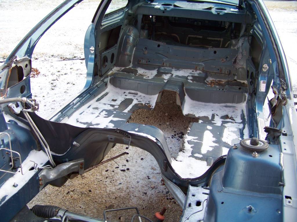
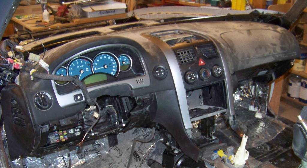
I first removed the original welded sheet metal dash section from the Lemans at the base of the windshield. I had to remove this anyway because I had rust in the lower windshield channel and had to weld a new channel in. I then removed the plastic and vinyl dash cover from the GTO donor and propped it up in place to check the fit. I did end up trimming the plastic sub structure of this assembly and therefore temporarily lost the defroster vents.
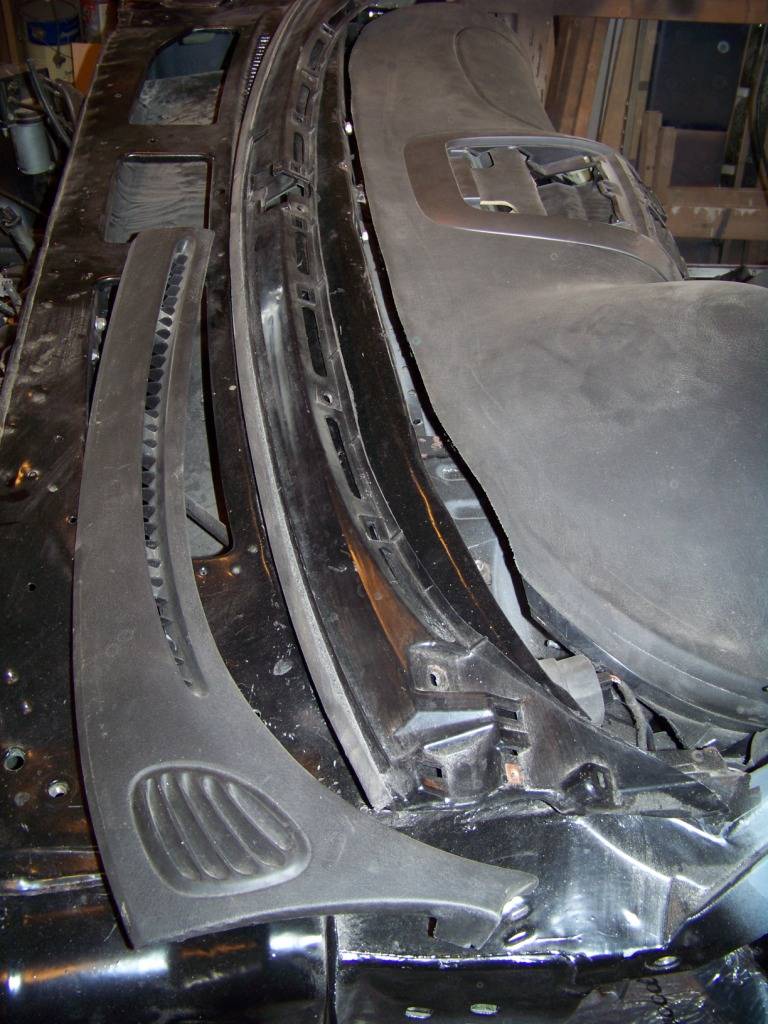
It's hard to see what is going on above since everything is black, but looking right to left we have the GTO dash pad, the windshield channel of the Lemans, the plastic section I cut from the GTO dash structure that was trimmed from the GTO dash pad, and the defroster vent grill. My plan is trim the vinyl top of the GTO dash a little more and install the defroster grills in the gap between the windshield channel and GTO dash pad.
I hope to relocate the vents into the vinyl area of the dash. As I was doing this mock up I took the seats from the GTO donor and placed them on the floor of the Lemans to get a feel for how it was going.
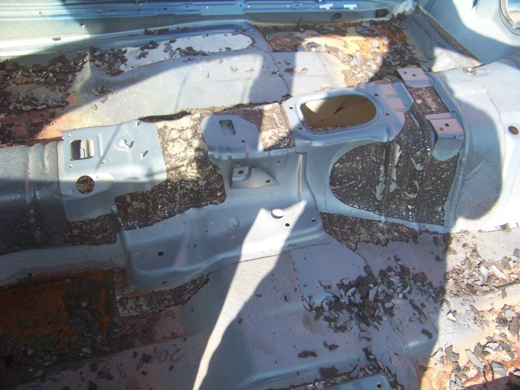
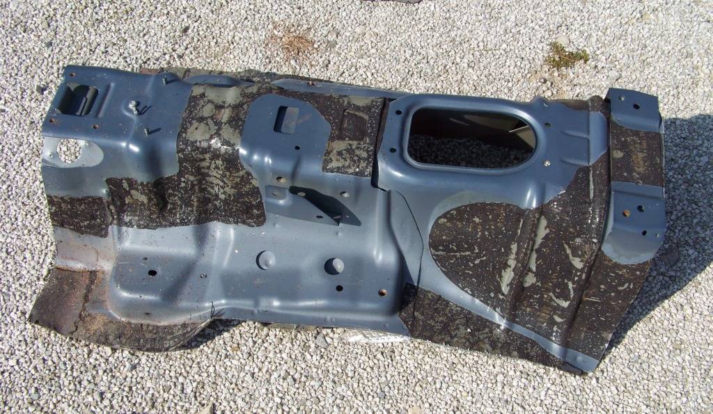
As I removed the dash components from the GTO donor, taking pictures as I went to aid re-assembly, I studied how everything went together and was supported. I decided to remove part of the firewall from the GTO donor and mount it into the Lemans to help support the new dash and the AC unit. This firewall/cowl structure also forms the ductwork for the defroster vents and supports the dash wire harness and steering column. I first removed the windshield (a mess since it broke and came out in pieces) and then cut the firewall out.
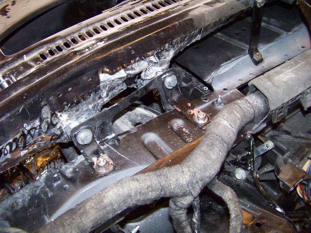
From there it was a trial and error process of fitting it into place, trimming areas here and there, and making brackets to support the GTO firewall into the Lemans. The two pictures below show the front and rear views of the removed firewall structure after all the trimming was done.
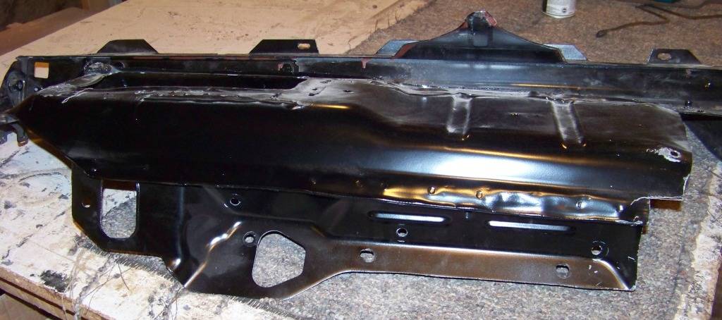
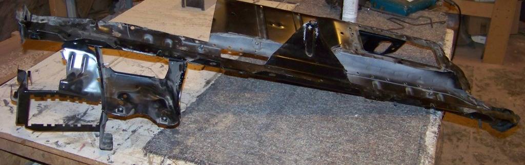
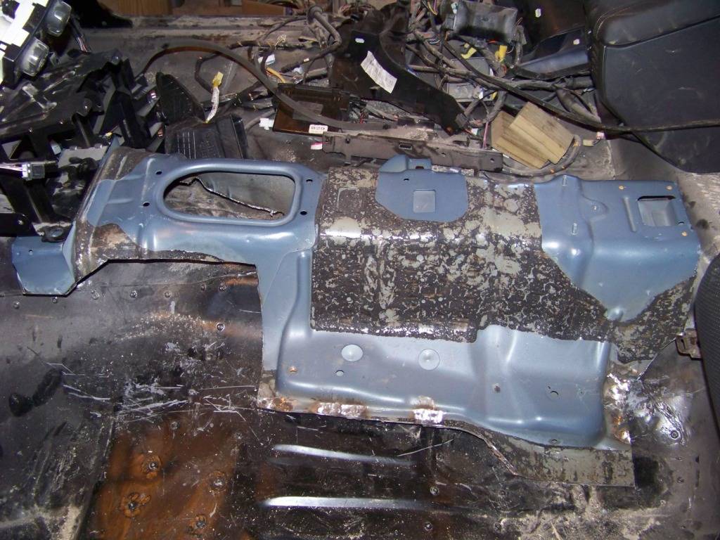
I tried to have the firewall supported at several different points so its sturdy. This GTO firewall ended up being about 4 inches behind the Lemans firewall.
The view below shows the attachment of the firewall above the steering column, these two small brackets connected the GTO firewall to the brake pedal bracket support locations on the Lemans.
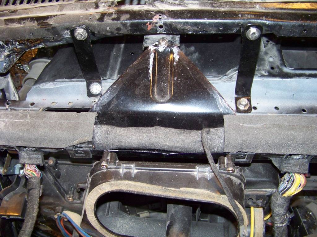
This picture shows the support of the GTO firewall in the center.
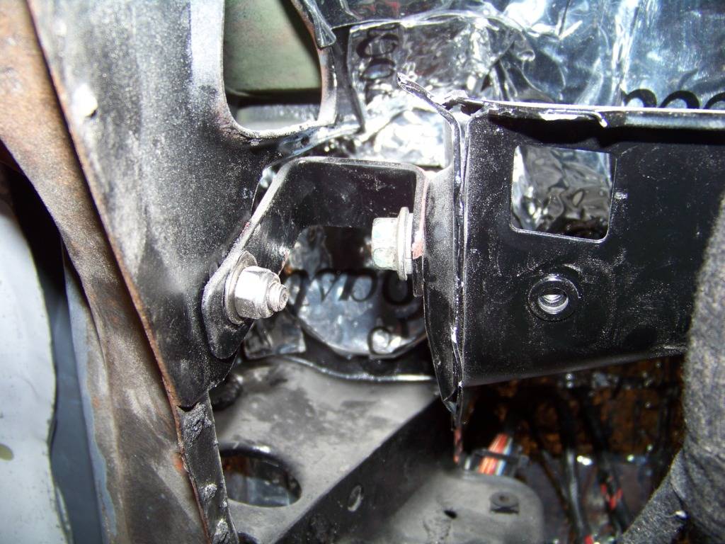
On the outer ends the GTO firewall is supported by these small u-shaped brackets.
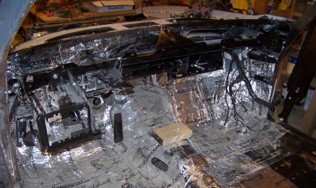
At this point the GTO firewall structure is attached and its just a matter of reinstalling the dash parts. First the dashboard wire harness is installed and the HVAC unit is bolted in. The large white object on the right is the passenger airbag module.
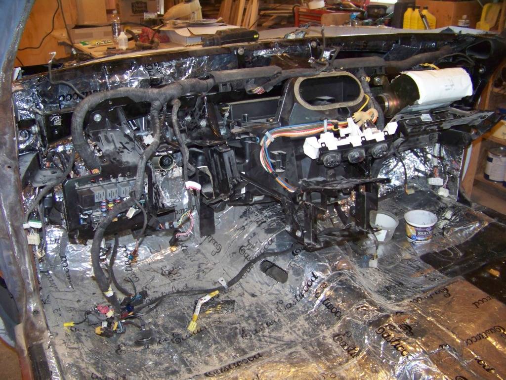
From here parts are installed in the reverse order in that they were removed, connecting electrical components as I go. This is pretty much where I am at the moment, except I do have the upper part of the steering column and wheel installed also.
I obviously still have a lot to do to in the interior such as redo the defroster vents, rework the door panels so they flow into the dash as they did in the GTO (the side AC vents are actually in the door panels), install the seats, install the console, install the rear seats, etc. All of these things will be covered in future posts, starting with the console installation.
Now that everything is hooked up I was able to successfully start the engine (after some delay finding a connector under the hood that wasnt hooked up). It pretty much fired right up thinking it was still in the GTO. I do have some codes such as two for the O2 sensors (the rear ones are obviously missing) and one for a injector circuit malfunction which I dont how that happened. But the engine seems to be running great; it was exciting to see and hear it come to life!
-
02-28-2013 #52
Registered User
- Join Date
- Nov 2011
- Location
- Springfield, OH
- Posts
- 58
Supporting the Console and Seats
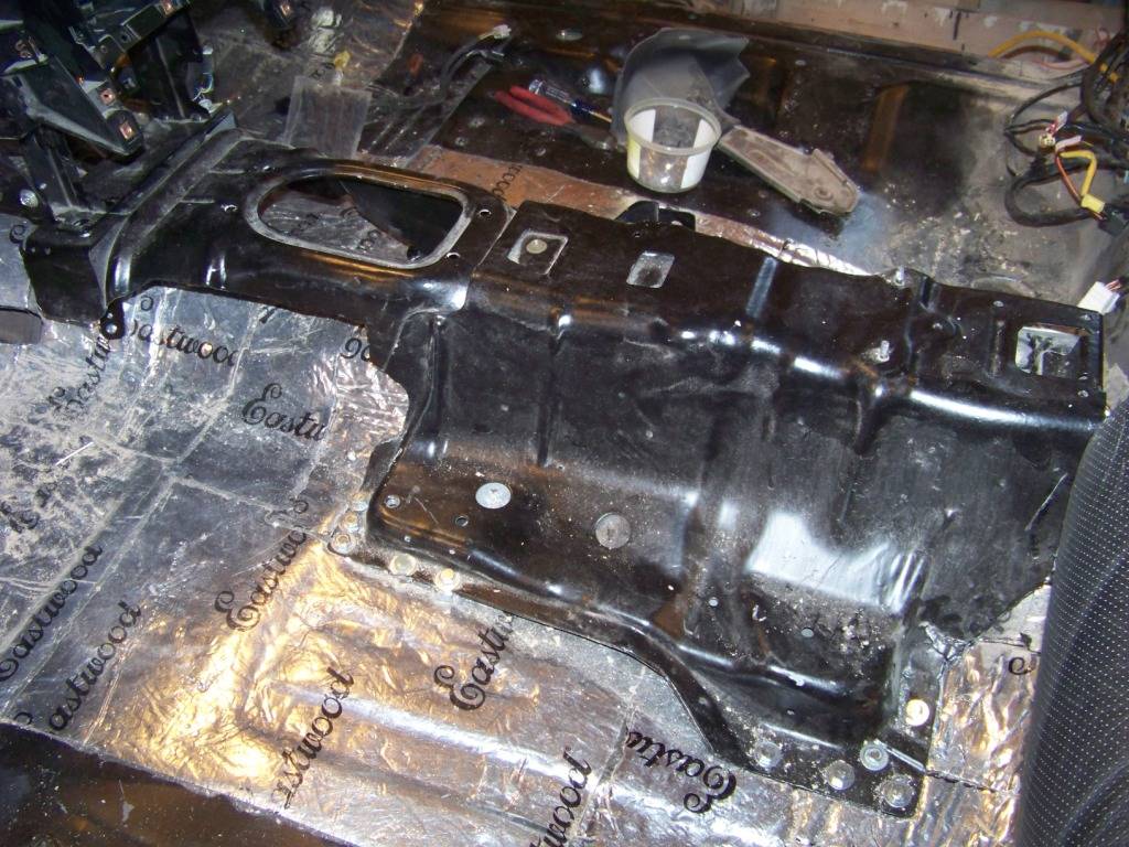
With the dash and steering pretty much all set, I moved further back and worked on the console area. I used the same philosophy I used for the dash in that I removed the structure from the GTO donor that supports the console and mounted it into the floor of the Lemans. This structure supports more than just the console, it also provides mounting points for the shifter, e-brake handle, and the inboard mounts of the front seats. As I did with the dash, I removed the structure from the GTO:
And trimmed it to fit onto the Lemans floor:
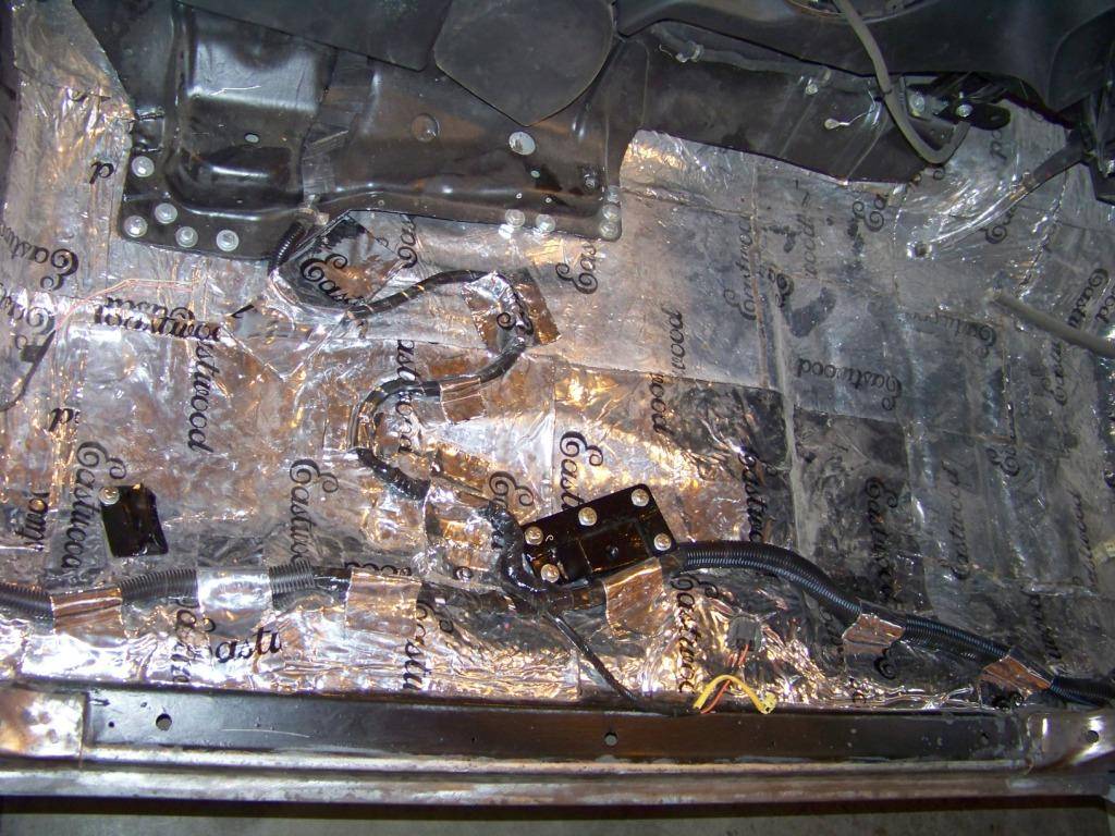
I still am not comfortable enough with my welding skills for sheet metal to install something like this with welding, plus my floor is already finished top and bottom, so I thought it better that I bolted it in. I used several 5/16 grade 8 bolts to install it. I knew it had to be fairly secure since this structure also supports the inboard seat mounts and the seats have integral seat belt buckles. Before bolting it in for good I removed all of the sound deadener, sandblasted it and painted it. I also installed sound deadening material to the floor before the tunnel installation.
From here the console components can be installed, starting with the shifter which I will document next.
-
02-28-2013 #53
Registered User
- Join Date
- Nov 2011
- Location
- Springfield, OH
- Posts
- 58
Shifter
Since my interior installation including the shifter was going to be a few inches further rearward from the transmission than it was on the GTO donor the shifter linkage wasnt going to work. I used the parts from the GTO with a longer rod I fabricated myself to connect the shifter to the transmission.
Shown below are the parts I fabricated.
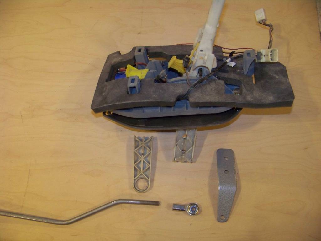
When I installed the shifter into the console substructure I found the lower lever on the shifter rubbed along the top of the Lemans floor. I tried to bend the lever with heat from a heat gun but ended up breaking it off. I realized it was too long to work anyway so that led to plan B which was to rework the linkage to work with a smaller lever. Originally the lever had a radius of about 6 inches, the reworked lever reduced that to about 4 ½ inches. I filled the cavities in the lever with epoxy and then made a lever extension from steel strap as shown above. The lever extension was just bolted to the remains of the plastic lever with two 5/16" bolts.
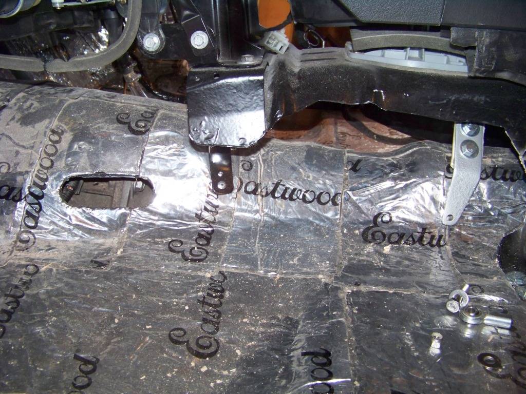
I cut an oval in the Lemans floor as shown to provide a place for the new linkage rod to pass through.
The lever on the transmission was shortened a proportional amount to get the same travel there.
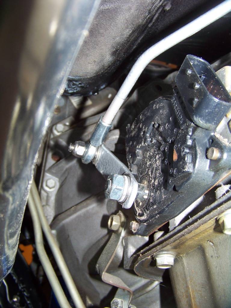
The final picture below shows the shifter and new reworked linkage installed. I made the linkage rod from 5/16 dia steel rod bent as required and then cut threads on both ends. I then installed rod ends that had female 5/16 x 24 threads and bolted them to each of the two levers with 5/16" bolts. I used rod ends bought from McMaster, part number 60645K331.
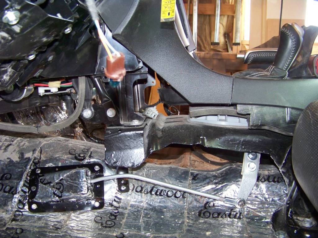
The cover was made from bent and welded sheet steel to cover the hole made in the floor, the cover has a hole in the back face of it to allow travel of the linkage rod. A little minor adjusting to the rod ends and it works great!
-
03-27-2013 #54
 Registered User
- Join Date
- Apr 2004
- Location
- Cedar Rapids, IA
- Posts
- 999
Wow! Still loving the backyard fab work.
How did you come across the wrecked GTO?Some times I'm fast sometimes I'm half-fast
-
03-28-2013 #55
Registered User
- Join Date
- Nov 2011
- Location
- Springfield, OH
- Posts
- 58
rohrt:
Thanks for your comment.
Post 12 on page 1 talks about the GTO I bought, how I bought it and the reasons I got it. I searched the internet for salvage cars and came across Salvage Autos Auction, you can search for cars there for what you want at salvage yards all over the country. My searching led me to East Coast Auto, I bought my GTO directly through them, they also arranged for shipping.
Let me know if you have any further questions.
Phil
-
03-30-2013 #56
Registered User
- Join Date
- Nov 2011
- Location
- Springfield, OH
- Posts
- 58
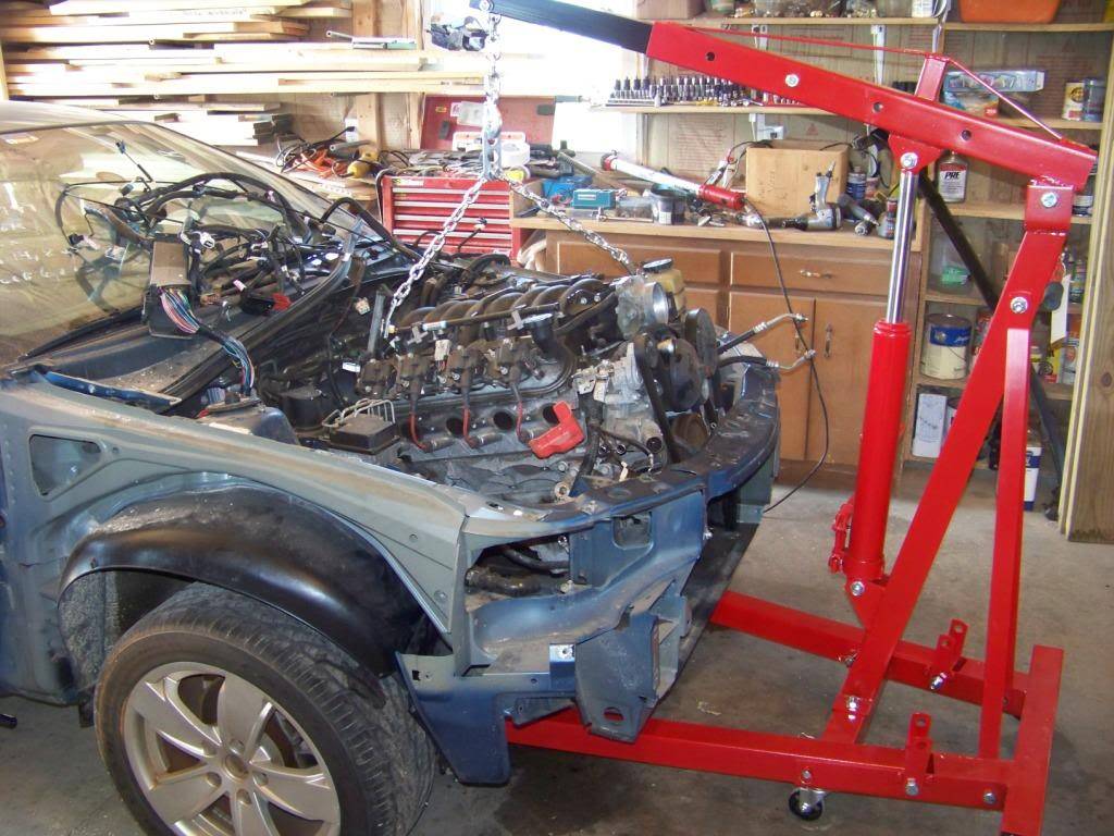
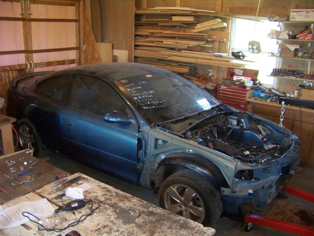
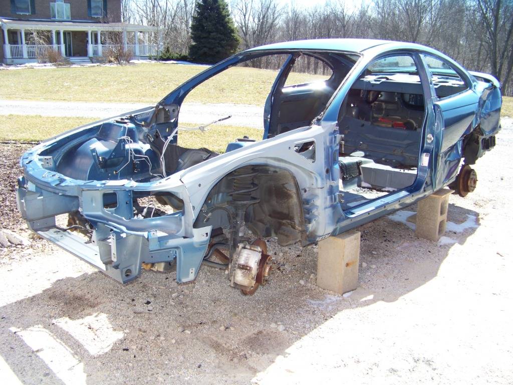
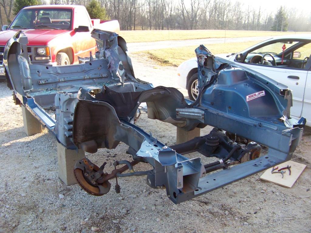
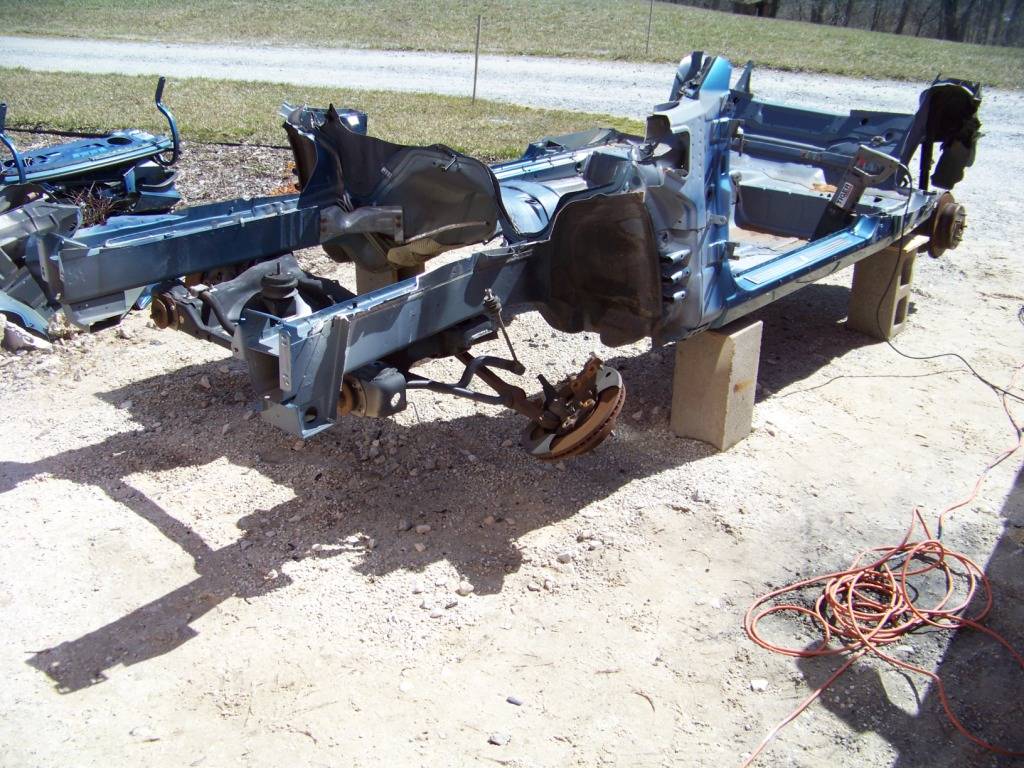
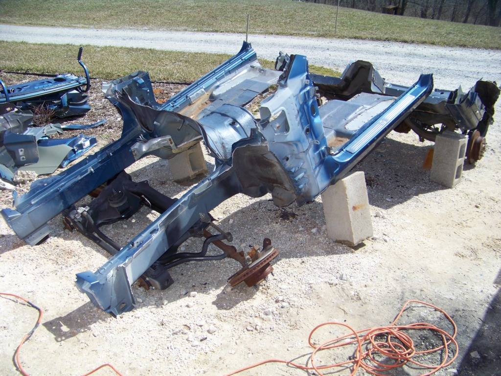
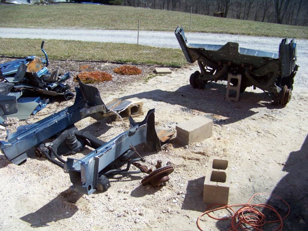
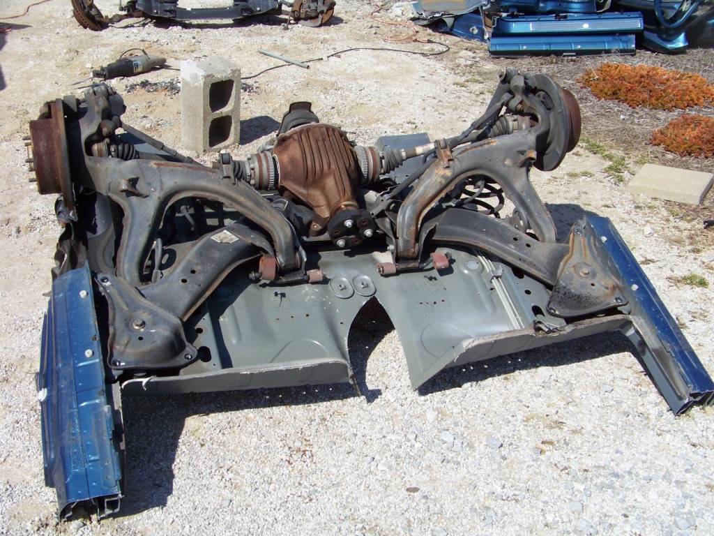
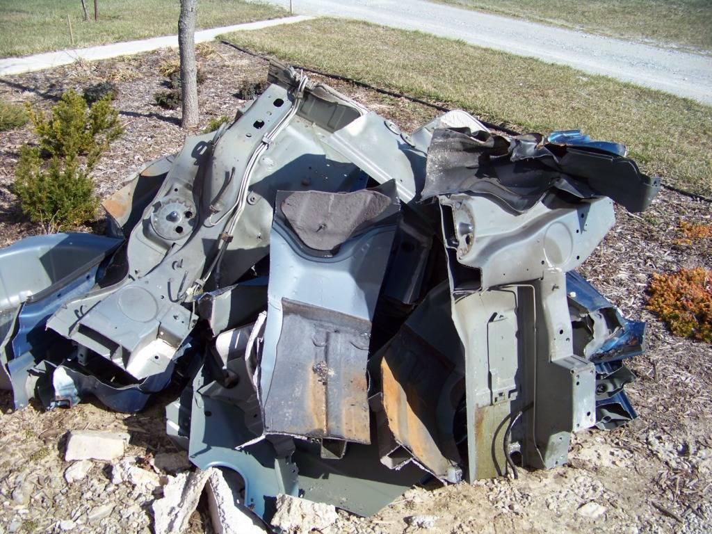
Donor Destruction
The last few weeks I have been selling unused parts both from the GTO donor and Lemans on ebay and Craigslist and have done pretty well with it. I have used some of the funds to buy parts for a 1970 GTO front end which I almost have everything for.
We finally got some warm weather here in Ohio so I took the opportunity to deal with the carcass of the donor. Thought it might be interesting to you . . .

-
10-17-2013 #57
Registered User
- Join Date
- Nov 2011
- Location
- Springfield, OH
- Posts
- 58
It's been several months since I last posted but I have been working steadily on the Lemans. I have been doing a variety of things as the mood strikes me and have time available, such as getting the driveline done, bodywork, and collecting parts. I have been on what seems like a quest to get all the parts for the 1970 GTO front end. It took me several months buying individual parts through craiglist and ebay but I finally have everything I need for the cloning process.
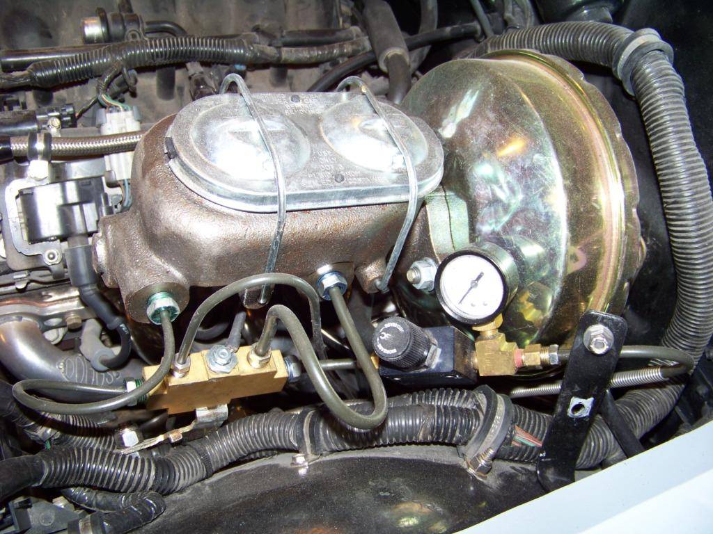
The next major milestone I have been working towards is getting the car to move under it's own power after being stuck in the shop for more than two years and who knows how long in the barn I bought it from (the most recent registration sticker on the plate was 1999). If it's going to move on it's own I thought it would be best if the brakes were working, so worked on finishing that up. I originally had the distribution block and adjustable proportioning valve on top of the frame just forward of the firewall. When I started adding brake fluid to the system of course it started leaking from one of the connections there which were pretty much inaccessible because of the body and inner fender were now installed. I wasn't really happy with the way I installed and plumbed those parts so I decided to tear it all out and redo it. I relocated the block and valve under the master cylinder so they were accessible and it is now much easier to get to the knob on the valve.
I had previously installed Speed Bleeders on the calipers to help in bleeding since most of the time I work alone. These were a help when I bled the system. I have never done it before so I took my time and tried to do it right. The pedal feels just a little soft but they do work to stop the car during the low speed trip I took on my driveway. The pressure gauge to the rear brakes doesn't move when I press the pedal, but I know the rear calipers are working. On my to do list is to check brake pressure at each caliper.
The last piece of the puzzle to get it moving was the driveshaft. The previous owner had given me a driveshaft, I sandblasted it and had it reworked by a local driveline company to work with the 4L60E and the correct length. I believe it was shortened by an inch or two, u-joints were replaced, and the correct transmission yoke was added. When I got that home I epoxy primed it and painted it. When I went to install it the x-pipe on the exhaust prevented the driveshaft from rotating down enough to meet the rearend. I decided to move the x-pipe forward so it was almost directly below the transmission yoke. This involved removing the two one-foot length pipes that were between the header collector reducers and the curved pipes that went to the x-pipe, thereby moving the x-pipe forward by that amount. These pipes would then be reinstalled forward of the mufflers. Unfortunately for that to happen means I would have to rework my transmission crossmember since it didn't allow the pipes to immediately curve towards the x-pipe. I always thought I would make another crossmember at some point anyway because I felt the first one I made was like something Dr Frankenstein would create.
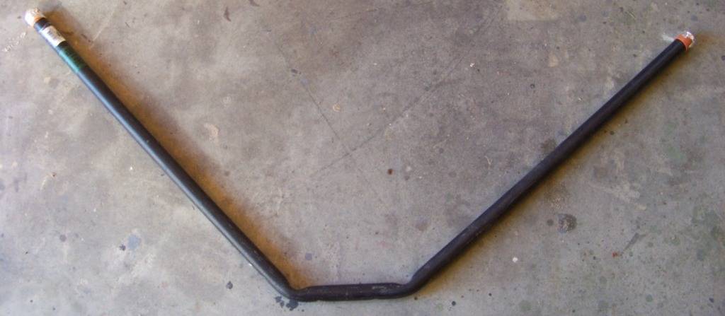
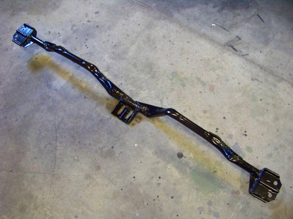
I wanted to make the next one a little simpler; I was inspired to create something similar to the Chevelle crossmember which is basically just a bent piece of tubing. I could have bought one and modified it as a lot of people do but didn't want to spend the money. I decided to use 3/4" iron pipe bent as necessary to get the shape I need. I did some measuring, drew up something on CAD that I thought would work and got started.
This picture shows the initial bends I made at the center of the crossmember where it supports the transmission.
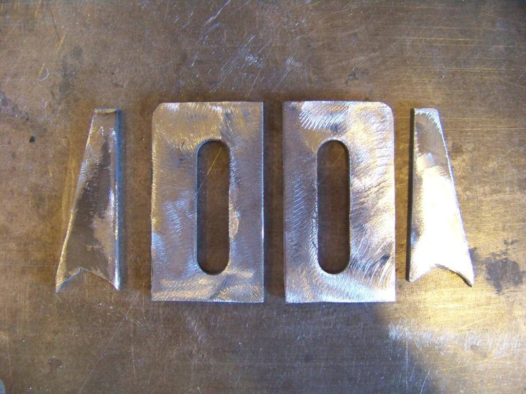
This shows the parts I made for the bracket that supports the transmission. The parts with the slots came from some brackets I removed from the 04 GTO (you never know what you will use from your donor car).
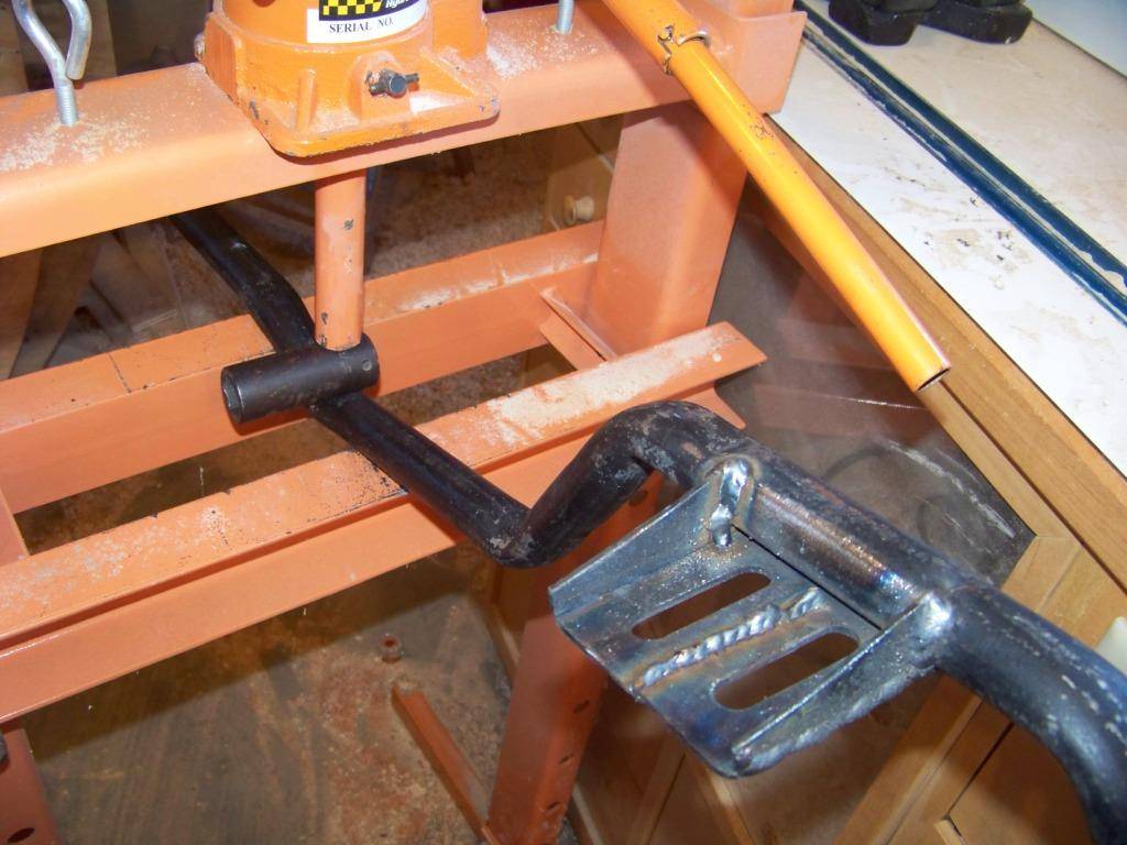
The next picture shows the process for bending the pipe. I used my shop press and a impact socket as shown to get the bends I wanted. It did kink the pipe quite a bit but I welded some gussets on as you will see. This picture also shows the transmission support bracket, but this was later removed and flipped over to get it to fit better.
The next picture shows the completed crossmember with gussets welded on at each bend to stiffen it. I also used the support brackets on the ends that I previously made for my first crossmember, this time welded on to give me a one-piece crossmember. The crossmember here has just been sandblasted in preparation for finish.
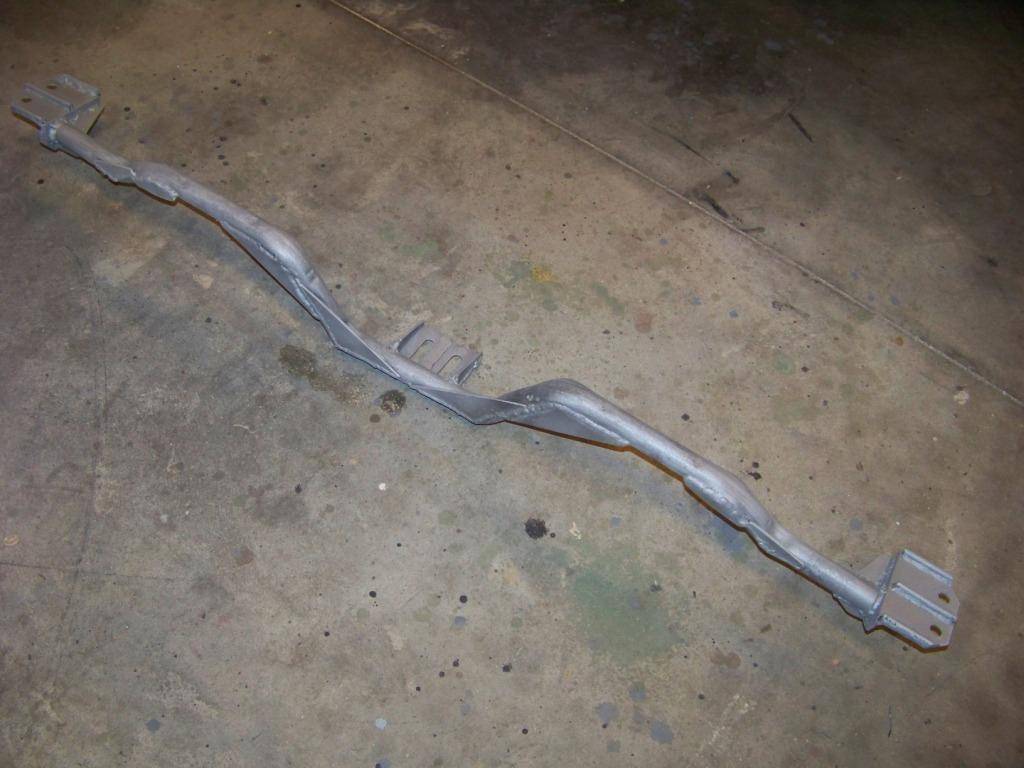
This picture shows the crossmember painted and ready for installation.
The next two pictures show the new crossmember installed. You can also see the new driveshaft I had made.
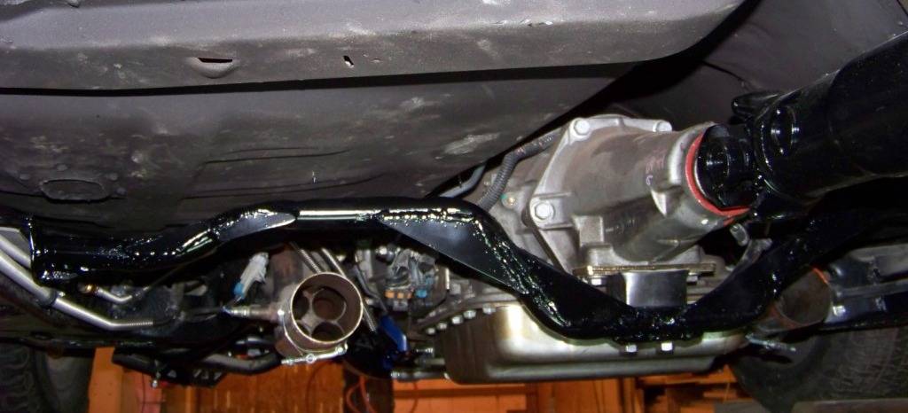
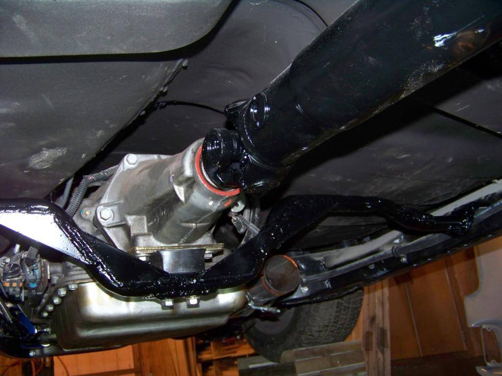
After this was all done I reinstalled the exhaust with the change I mentioned before, put those nasty old tires on and pumped them up. The car was then lowered to the floor for the first time in more than a year.
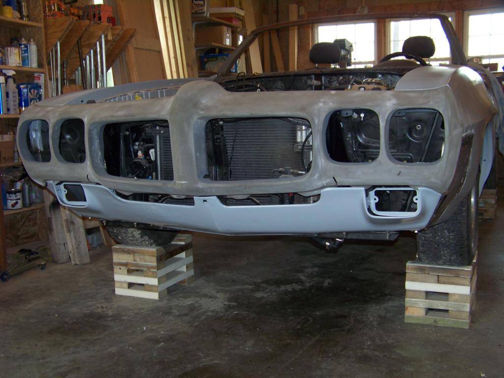
And then finally the major milestone as I mentioned, the car can now move under it's own power for the first time in many years:
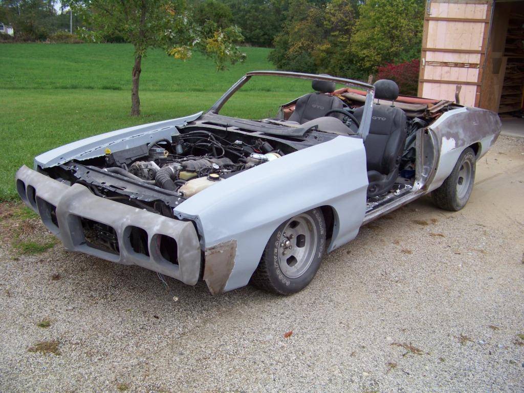
I took it for one trip up and down my gravel driveway. The front suspension is really low, the front crossmember is just 2-3 inches above the ground, something I need to look into to. The rear is a little high, but once more weight is added to the car that should come down some.
In the picture above you can also see the the 70 GTO bumper I am getting ready for paint and the rework of the Lemans fronts fenders into GTO fenders. I will document this work in a future post.
-
11-30-2013 #58
Registered User
- Join Date
- Nov 2011
- Location
- Springfield, OH
- Posts
- 58
Time for a couple of small updates. I have been hopping around from one thing to another as the mood hits me.
In my previous update I mentioned that the front end was really low. I ended up inserting all of the coil spring spacers in the lower control arm spring pocket. That raised the front about 2 1/2 inches. I am happy with it for now, when the car is almost done with all the weight on it and the final wheels & tires installed I can fine-tune it then.
This post talks about redoing the transmission cooling lines, my next post will be about the outer seat brackets.
Transmission Cooling Lines 2.0
I had some leaks from the transmission cooling lines that I originally cobbled together from the 04 GTO lines and several AN fittings (See post #54). I decided to simplify the lines and reduce the number of connections.
At the bottom of the transmission I had some hard tube adapters, one was leaking and it was between the header and transmission and therefore hard to get to to tighten it. I got two more -6 AN 3/8 hard tube adapters (part number SUM-2200077B at Summit) and re-cut the 04 GTO transmission lines lower down closer to the transmission for easier access:
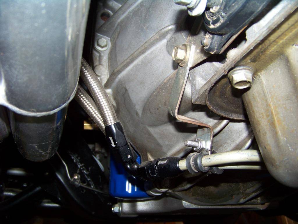
I made new braided steel lines with 90 degree hose ends.
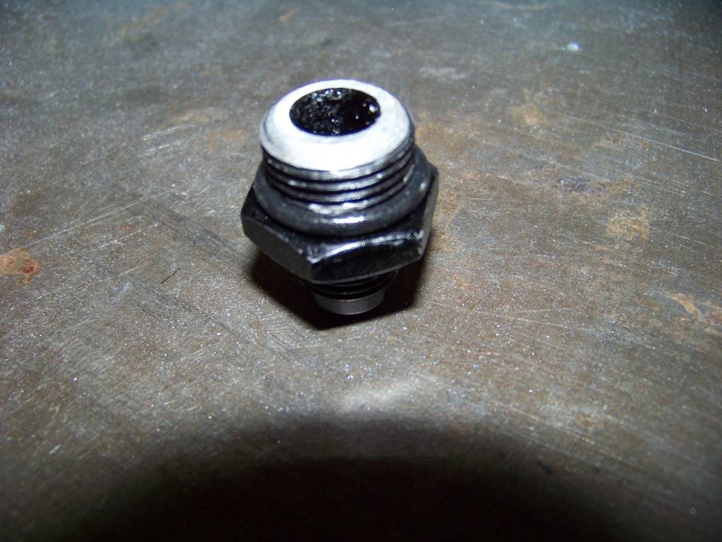
I originally had more hard tube adapters on the tube ends that originally connected to the 04 GTO trans cooler in the radiator, but I had some leaks there too. I went ahead and bought some adapters to fit into the connections in the GTO radiator and converted the connection to -6 AN. These adapters (from Fragola, part number FRA-460618 at Summit) convert the 18mm x 1.5 mm threads on the transmission cooler connection on the radiator to -6 AN. One issue though is that the threads on the adapter were deeper than the threads on the recess in the radiator. I ground down the threaded portion of the adapter so it would fit:
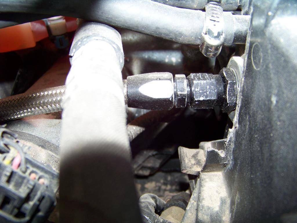
This final picture shows the upper connection at the radiator, the lower connection is similar. From right to left we have the GTO plastic radiator, a rubber o-ring to seal the new adapter, the trimmed adapter, and the -6 AN hose end and hose:
This new version of the transmission cooling lines is working out well with no leaks.
-
12-01-2013 #59
Registered User
- Join Date
- Nov 2011
- Location
- Springfield, OH
- Posts
- 58
Outer Seat Brackets
As promised this post will talk about the fabrication and installation of the outboard seat brackets. See post #93 that shows using the tunnel structure from the GTO donor for the inner seat bolt connections. I considered using the sheet metal bracket for the outer seat bolt connections from the GTO donor but due to the floor shape in the Lemans it would have required a fair amount of work. So I thought if I am going to go to all that effort I will make my own more substantial brackets.
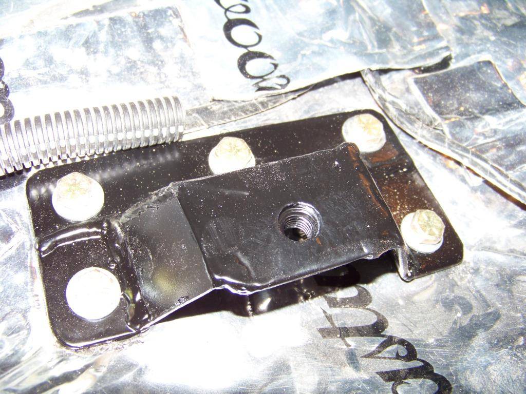
The picture below shows the brackets I made installed on the passenger side floor, the following picture shows the driver's side floor. The forward bracket on the passenger side had to be installed at an angle due to the shape of the floor in that side. You can also see here I secured the wiring harness in this area with leftover scraps of sound deadener, I thought that worked out well. In areas where the carpet would cover the harness and it could get stepped on I added convoluted harness cover.
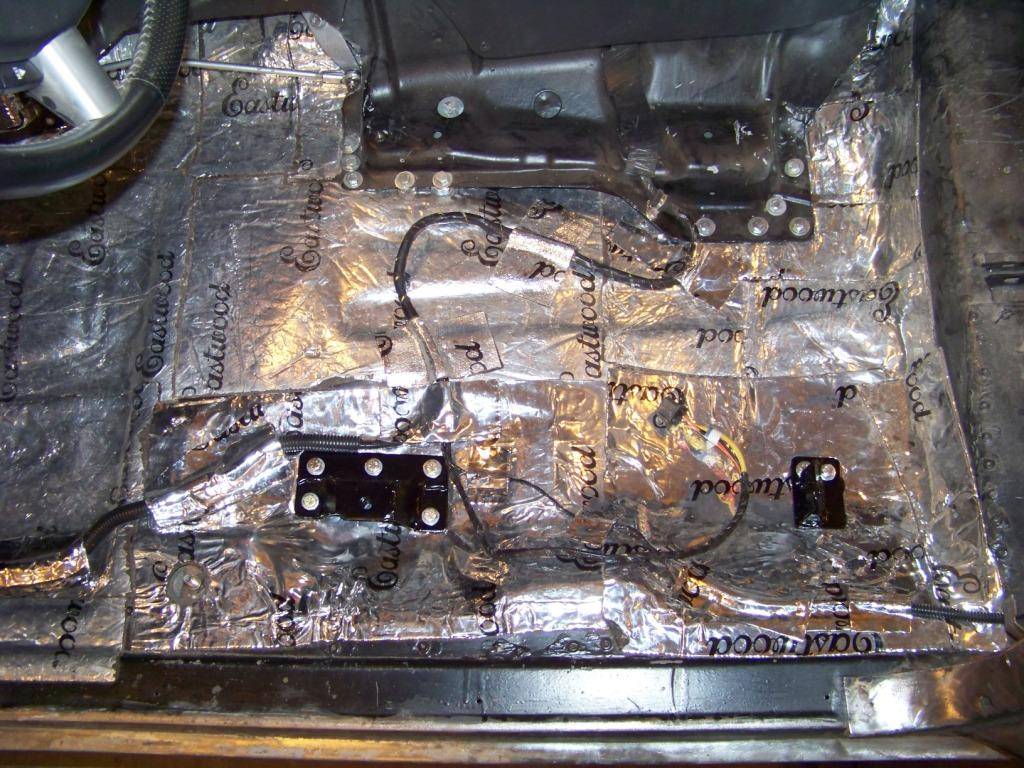
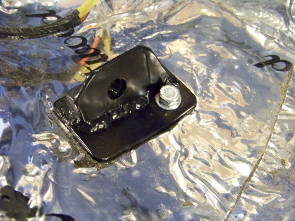
The next picture shows the forward bracket on the driver's side. These brackets are made from 1/8" steel welded into a tower-like shape as shown. The threads for the seat bolt are a flanged metric nut welded in place onto the underside of the bracket similar to what the GTO donor had. The brackets are bolted through the floor with several 5/16" bolts.
This picture shows the rear bracket on the driver's side.
Once these brackets were installed I then tried fitting the carpet from the 04 GTO. With some trimming here and there it fits okay, but I think at some point I will get the correct a-body carpet. My future desire is to someday redo the interior in a two-tone tan and brown theme (I think that would look good with the dark blue I have planned for the outside), at that time I can get a brown a-body carpet.
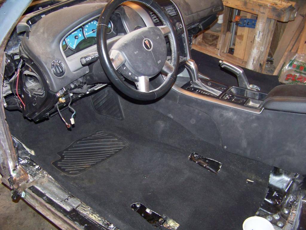
The carpet had to be trimmed a little around the new outer seat brackets, then the seats were installed using the original bolts from the GTO donor. The seats themselves were trimmed slightly around the rear outer brackets to comform to the slope of the Lemans floor.
That's all I will probably do to the interior for now, my next major effort will be towards the bodywork with the goal of maybe getting it in paint sometime over the winter.
-
12-08-2013 #60
Registered User
- Join Date
- Nov 2011
- Location
- Springfield, OH
- Posts
- 58
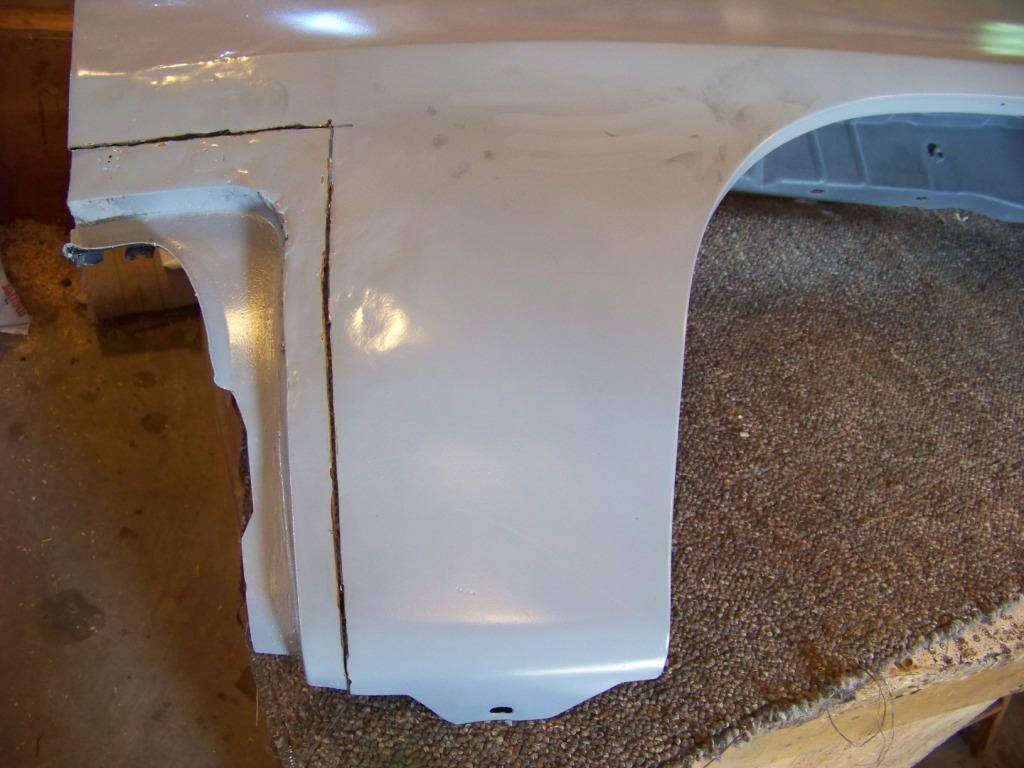
Front Fender Rework
When I bought the car it came with fenders for a 1970-2 Lemans that were in really good condition with minimal rust behind the wheel wells which I patched. But since I decided to clone the car into a 1970 GTO they wouldn't work with the rubber GTO bumper. 1970 GTO front fenders are available as reproductions but they are $600 a side, plus I would have had to fuss around selling the Lemans fenders. I came across some info on the Internet about reworking the Lemans fenders into GTO fenders so that's what I did. At the moment I have more time than money.
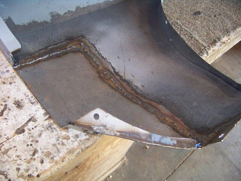
The first step is to remove the pocket in the front of the fender that the Lemans bumper and front valance fit into:
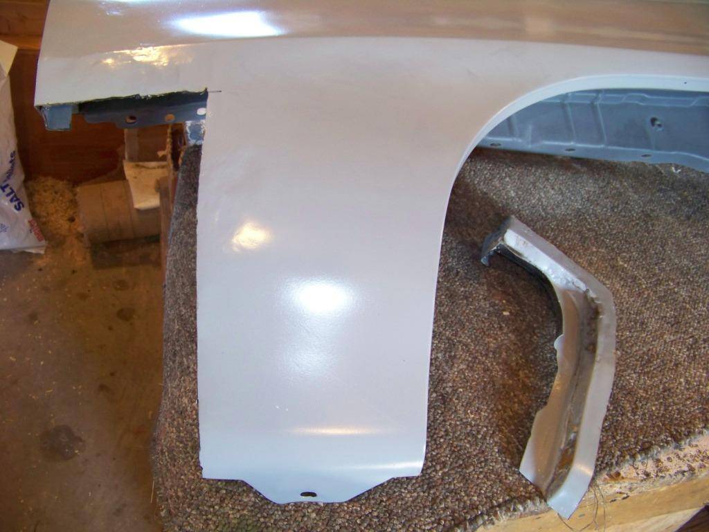
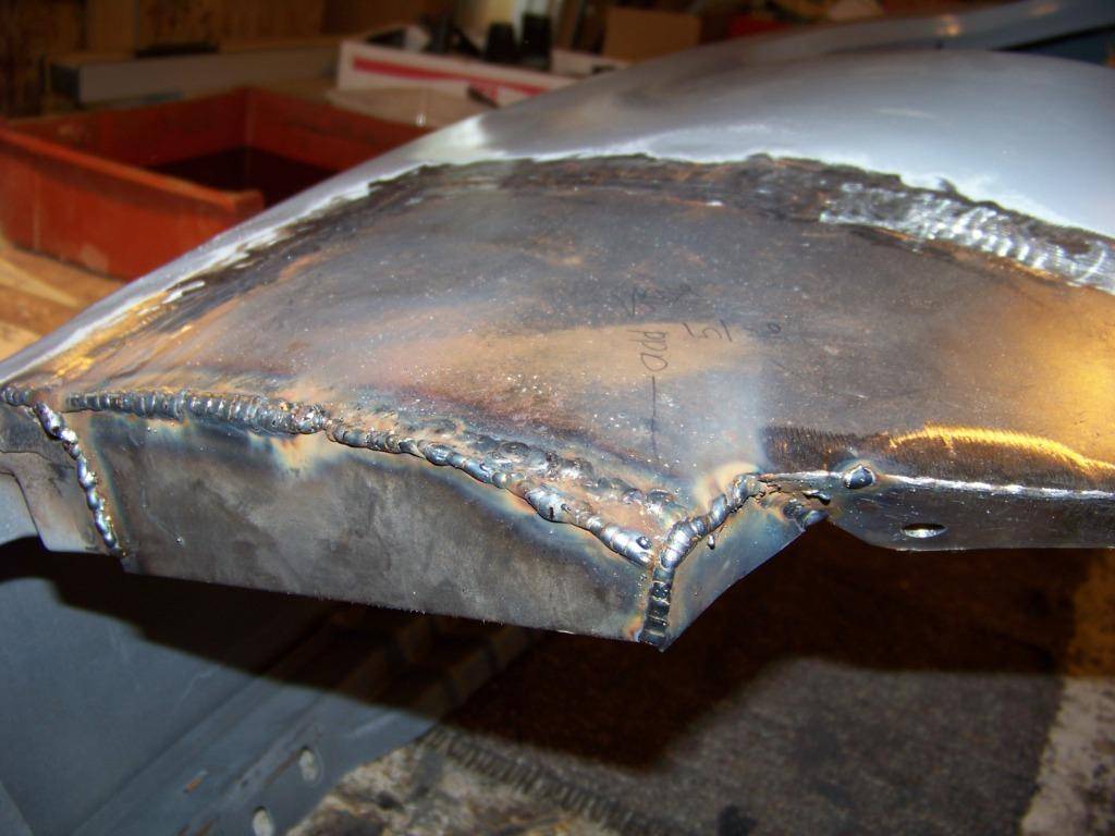
Then I shaped some sheet metal to match the curvature of the fender and welded it in:
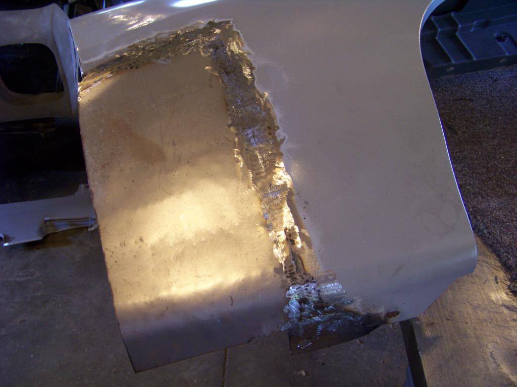
From there it was fitting on additional parts on the front of the fender where it meets the lower valance panel and rubber bumper:
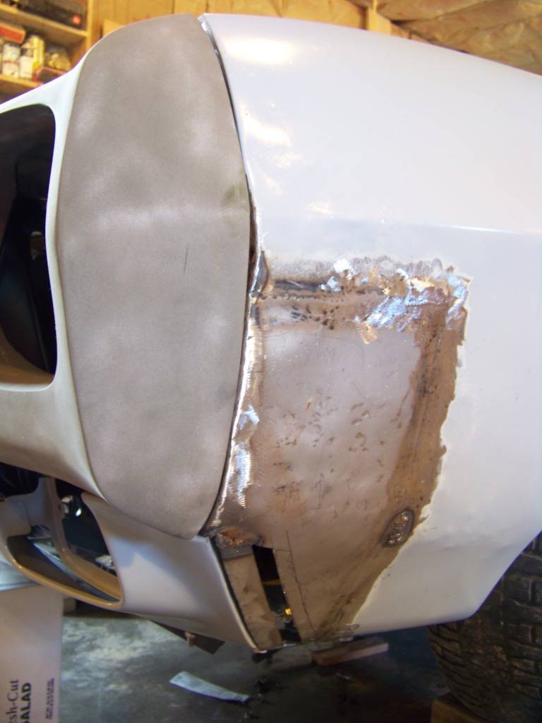
I didn't have any measurements or example GTO fender to copy from, this was all just winging it to some degree, using pictures on installations I found on the internet. As you can imagine, this required a lot of trail and error and fitting. For example, I found my initial effort to support the valance panel was too far to the rear so I had to cut that portion off and move it forward:
After more such tweaking I was pretty happy with the outcome:
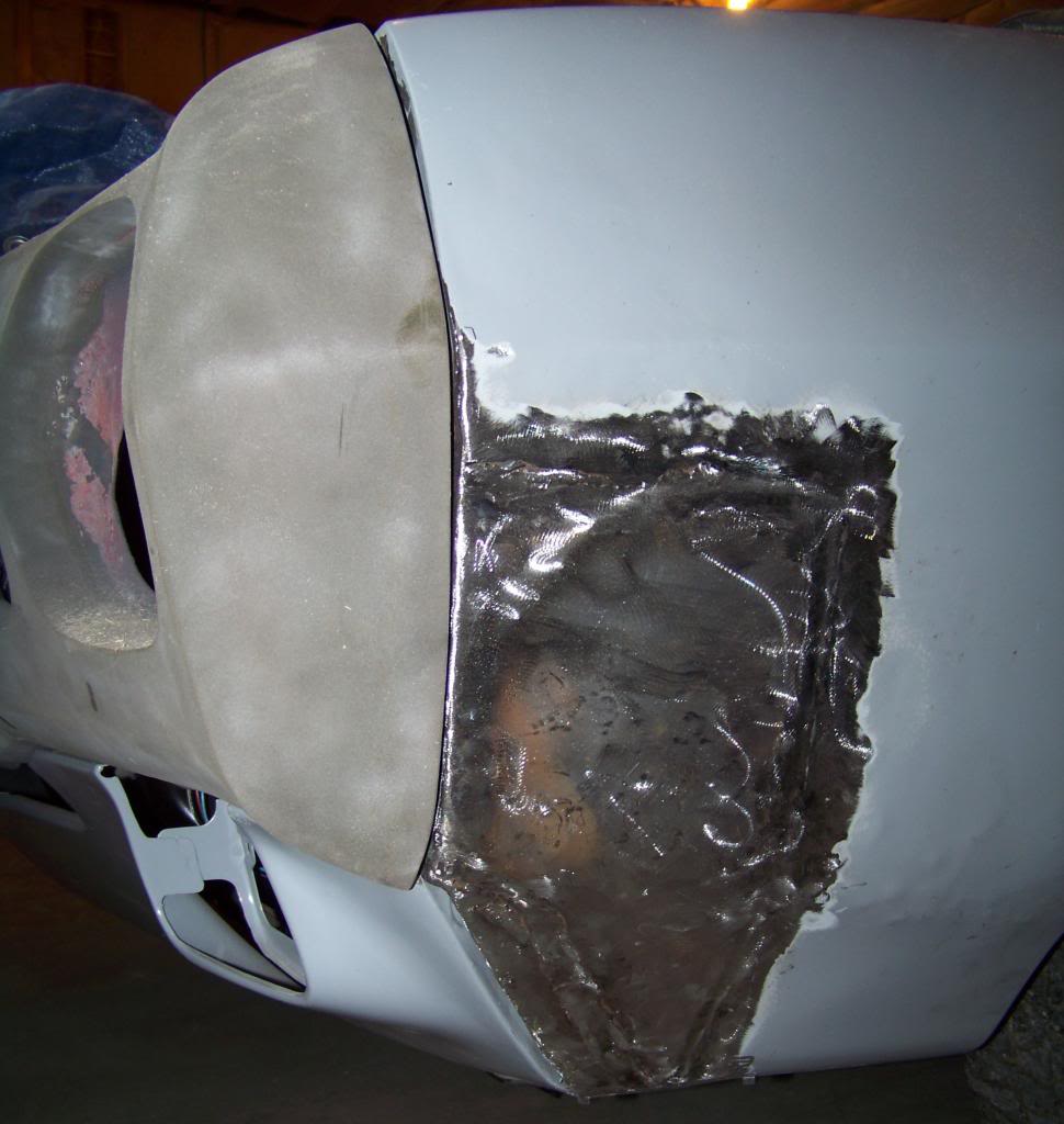
I didn't try to add the cutout for the front side market light, I figure I would just do without it and go for the shaved look. After some hammer and dolly work and some filler this should look pretty good. It actually appears to fit better than some of the pictures of finished cars I found online.
After doing both fenders and rough fitting the bumper and valance panels I came to this point:
It feels good to have the front sheet metal well on it's way, I just need to fit the doors and hood and check the alignment of everything.
Since then I have been working on the back; starting to replace the passenger quarter, reworking the trunk lid, and repairing some minor rust issues other places. Those will be featured in future posts.

 Reply With Quote


