

Results 1 to 20 of 25
Thread: cracked 4 bar bushing
-
05-23-2009 #1

 Registered User
- Join Date
- Aug 2004
- Location
- Crown Point, Indiana
- Posts
- 1,107

cracked 4 bar bushing
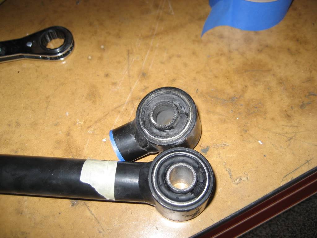
 What could have caused this ? This is a pic of my ART four bar bushing (sleeve)
Last edited by GRNOVA; 05-23-2009 at 01:57 PM. Reason: improper terms
-
05-23-2009 #2 -Moderator/Sponsor-
- Join Date
- Apr 2001
- Location
- The City of Fountains
- Posts
- 16,117
Are you referring to the sleeve inside the bushing?
Andrew1970 GTO Version 3.0
1967 Cougar build
GM High-Tech Performance feature
My YouTube Channel Please Subscribe!
Instagram @dr__efi
I deliver what EFI promises.
Remote Holley EFI tuning.
Please get in touch if I can be of service.
"You were the gun, your voice was the trigger, your bravery was the barrel, your eyes were the bullets." ~ Her
05-23-2009 #3
Registered User
- Join Date
- Aug 2004
- Location
- Crown Point, Indiana
- Posts
- 1,107
yes
05-23-2009 #4
-Moderator/Sponsor-
- Join Date
- Apr 2001
- Location
- The City of Fountains
- Posts
- 16,117
I don't know for sure, but I would not be surprised if the inner tubes were split like that to begin with. Looks like a very clean, straight "crack." Originally Posted by GRNOVA

Andrew1970 GTO Version 3.0
1967 Cougar build
GM High-Tech Performance feature
My YouTube Channel Please Subscribe!
Instagram @dr__efi
I deliver what EFI promises.
Remote Holley EFI tuning.
Please get in touch if I can be of service.
"You were the gun, your voice was the trigger, your bravery was the barrel, your eyes were the bullets." ~ Her
05-23-2009 #5
Registered User
- Join Date
- Aug 2004
- Location
- Crown Point, Indiana
- Posts
- 1,107
Sorry pic is a little big. When I pulled the drive shaft I also noticed that the rear has hit the floorboard. Also that the pinion angle is -5 and the engine is -3. Shouldn't the pinion be +3 or +4?The red lines are the cracks I was talking about.
05-23-2009 #6 Registered User
- Join Date
- Sep 2004
- Posts
- 159
It looks like the bushing doesn't have enough give to allow the suspension to swivel and move about so it is binding and cracking instead. Here's a visualization demo: grab a broom handle with both hands palms down. Place your elbows at your side with your arms sticking straight forward. Pretend your arms are links and the broom handle is the axle. Now raise one hand about two inches like as if you hit a bump in the road. Notice how both wrists have to twist and that your arm will not go straight up and down but in an arc relative to the other hand. I hope that helps explain why you need a bushing with some give to them (like rubber) to allow this kind of movement instead of a hard bushing (like plastic or polyurethane)

Brian
05-23-2009 #7
Registered User
- Join Date
- Aug 2004
- Location
- Crown Point, Indiana
- Posts
- 1,107
KQM052...These are steel inserts in a rubber a bushing. But I do see what you are saying, maybe this was too tight and instead of moving it just cracked. I will call Airride Tuesday. As far as the pinion angle is concerned if the tran. is down 3* then the pinion should be up 3* to have correct pinion setting does this sound right?
05-23-2009 #8 Registered User
- Join Date
- Nov 2008
- Location
- So. Cal.
- Posts
- 1,240
Hey Tim. I see the long split on the inner sleeve, I think that is supposed to be there. I have some out right now and there is a line showing its a split sleeve. On mine the joint is tight though, where yours looks like it has spread abit.
But whats confusing for me is inside the bore, at the back end on yer pic, where you show all the obvious cracks. What is that?? Isnt it a through hole for a bolt. The pic is deceiving for me. It looks like there is a solid (was solid till it cracked) "plug" like item? I cant make out what that cracked area is??
I could see the sleeve spreading and opening up the joint if the bolt wasnt tightened down enough. They need to be pretty tight so the saw tooth end bites into the mounts causing it, the sleeve, to be immobile while the rubber takes the rotating action, and there is all the rotational binding we all hear about with rubber bushings.
But to be honest, I dont see the issue. Rubber bushings are so compliant it only takes a lil hand pressure to move the control arm or trailing link through its entire working (road travel) travel I dont see it as an issue.
But anyway. Ummm, whats the cracked surface in the pic at the far end of the bore? JR
05-24-2009 #9 Registered User
- Join Date
- Oct 2004
- Location
- IL/TN
- Posts
- 908
can't tell much from the out of focus pics
https://www.protouringf-body.com "doing what they say can't be done"
05-24-2009 #10
Registered User
- Join Date
- Aug 2004
- Location
- Crown Point, Indiana
- Posts
- 1,107
I am sorry about the out of focus pic but I took several and this was the best one. see if the video helps.
05-24-2009 #11
Registered User
- Join Date
- Nov 2008
- Location
- So. Cal.
- Posts
- 1,240
Holy crap!!! That sleeve is severely fractured!!!! Im on my desk top computer now (lap top last night) and can actually see what it is.
The entire sleeve has shattered.. Dude!! That looks like a material heat treating quality control issue. No matter what, that metal should not have fractured like that.
If the tempering process was not adhered to then it may be overly hard (BRITTLE). I have a full on hardness testing and heat treating setup here. Id love to check that sleeve. Bet its on the high side. Id like to see what the manufacture spec'ed out for the final tempered hardness. If they speak english that is
Never know where some parts come from. Could be assembled in the US with overseas parts. And dont even get me wrong, nuthing wrong with that, sometimes. But I have found QC can goe out the door after the first part left with the customer.
Like to hear what ART has to say. Im sure they will stand good with their product. JR
11-15-2009 #12
Registered User
- Join Date
- Aug 2004
- Location
- Crown Point, Indiana
- Posts
- 1,107
only 5 months
Well I don't want to start another post since I have the same problem as I had in May CRACKED bushings on my air 4 link ends. I need to find a heim joint that I can press into the bar ends. Anyone have any ideas.
Last edited by GRNOVA; 11-15-2009 at 08:31 AM. Reason: Title
11-15-2009 #13 Registered User
- Join Date
- Aug 2004
- Posts
- 2,413
to start press out the rubber bush and get some measurments..
Nothing says "I built this" better than tool marks and dykem blue..
Follow my 3 link build. https://www.pro-touring.com/forum/sh...ad.php?t=61592
11-15-2009 #14 Registered User
- Join Date
- Apr 2009
- Location
- san diego
- Posts
- 5,101
the COM series spherical eyes may be what you are looking for.
My build thread: https://www.pro-touring.com/showthre...ing&highlight=
The mustang build thread: https://www.pro-touring.com/showthre...el)&highlight=
11-15-2009 #15 Registered User
- Join Date
- Sep 2006
- Location
- Henderson,NV
- Posts
- 2,870
My guess would be that the rubber was fatigued enough that it wasn't adequately supporting the sleeve. It's very possible the sleeve was binding on the outside housing. I changed over to a QA1 kevlar endlink after tearing up a couple bushings identical to those. I replaced my upper arms all together and cut off the axle ends and tapped them for new end links. I could tell the rear end was able to articulate easier the first time I drove the car.
 Todd
Todd
11-15-2009 #16
Banned
- Join Date
- Aug 2003
- Location
- Orlando, FL
- Posts
- 8,745
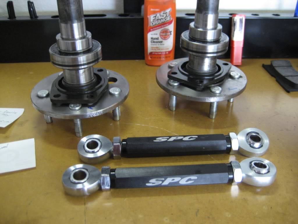
This is what we do the the Prodigy Bar ends.
As Todd said, you can cut and tap the rods 3/4 X16, the DOM tub is the perfect size for this. besides totally liberating the rear end movement, you also can get some wheelbase adjustability and easier pinion angle adjustment. We do this on our 4 link kits (Prodigy Bar) at the factory and call it our swivel end kit. Here is exactly what we do. We have the parts in a kit including the taps for $240 or you can get them on your own under these part numbers
Rod Ends
(4) QA1 XMR10-12 XMR
(2) QA1 XML10-12
Jam nuts
(4) JNR 12S
(2) JNL 12S
Spacers
(16) SG 108
Taps
3/4 X 16 Right Hand
3/4 X 16 Left HandLast edited by ProdigyCustoms; 11-15-2009 at 06:03 PM.
11-15-2009 #17
Registered User
- Join Date
- Aug 2004
- Location
- Crown Point, Indiana
- Posts
- 1,107
here are the measurements: Originally Posted by LowBuckX
11-15-2009 #18
Registered User
- Join Date
- Aug 2004
- Location
- Crown Point, Indiana
- Posts
- 1,107
Would these be able to be used without replacing the brackets that are already welded in place. Originally Posted by ProdigyCustoms
11-15-2009 #19
Banned
- Join Date
- Aug 2003
- Location
- Orlando, FL
- Posts
- 8,745
Originally Posted by GRNOVA
Yes, but I forgot the spacers
(16) SG 108
11-15-2009 #20
Registered User
- Join Date
- Aug 2004
- Location
- Crown Point, Indiana
- Posts
- 1,107
Frank, are these on you website? Where do I look up the part numbers.
I found this site BTF


 Reply With Quote


