


Results 1 to 19 of 19
Thread: need help making a crossmember.
-
06-04-2008 #1
 Registered User
- Join Date
- Feb 2008
- Posts
- 148
need help making a crossmember.
not sure if this should be in the 'wanted' section or not, so if it belongs there, please move thanks.
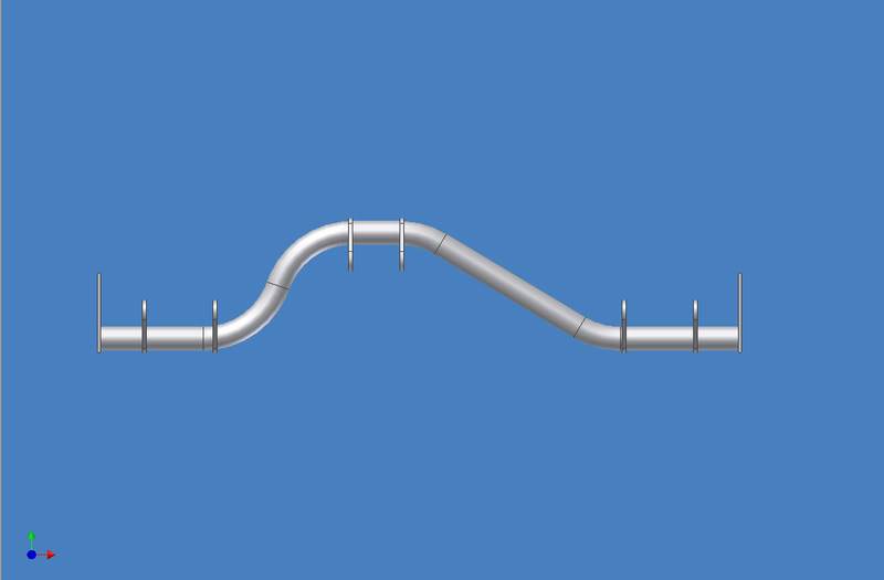
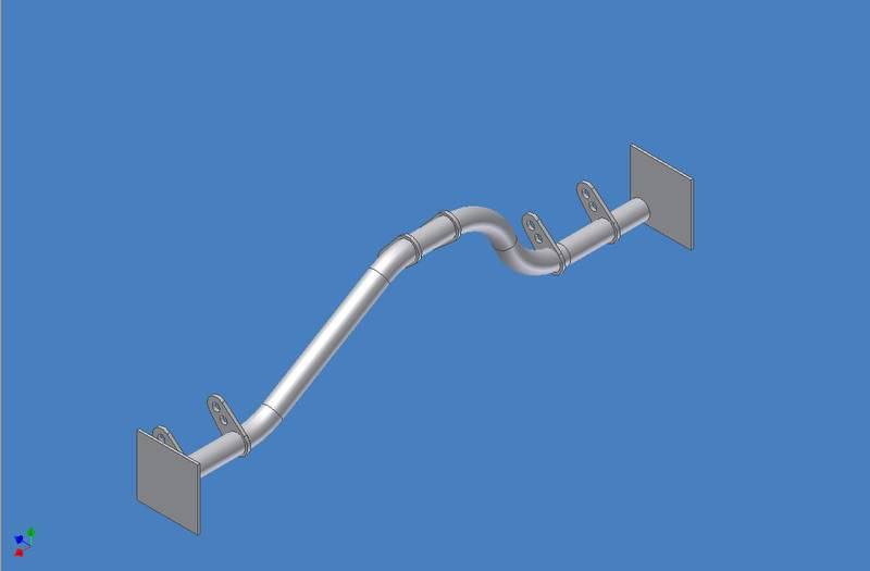
soo, i am having a hard time finding a place that can bend me some thick tubing for a crossmember on my truck.
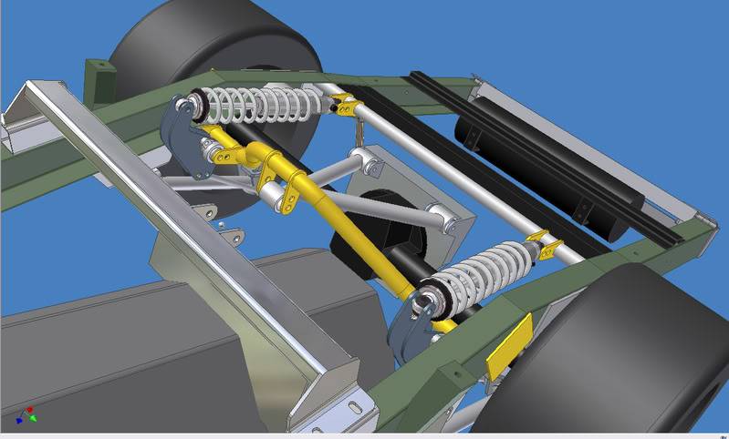
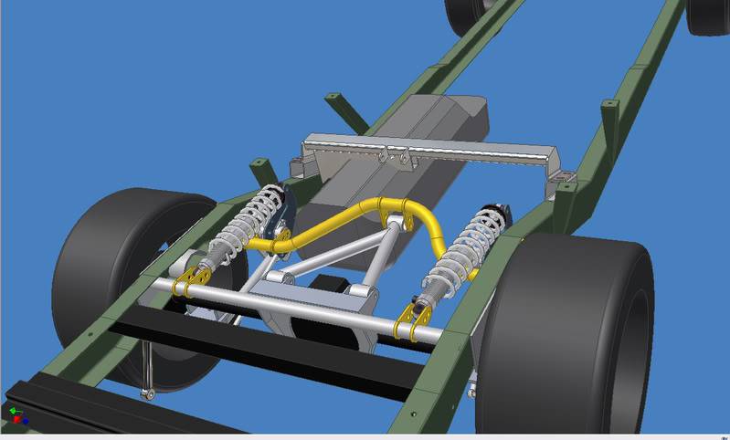
in CAD i have it designed with 1.5" dia 1/4" wall tubing.
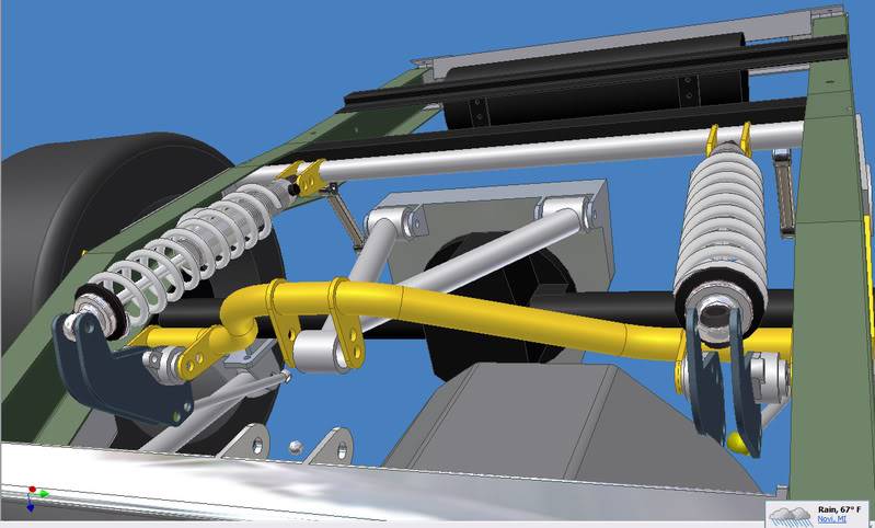
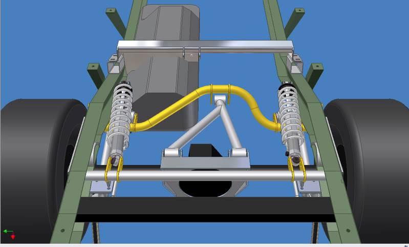
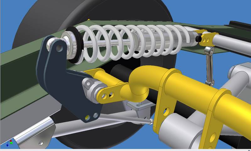
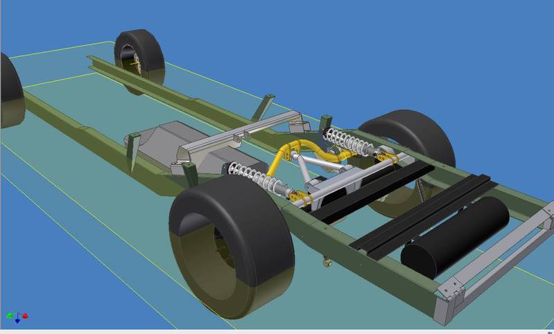
here are a couple screenshots of what i am trying to get.
http://i113.photobucket.com/albums/n...D/6c4d59f3.jpg
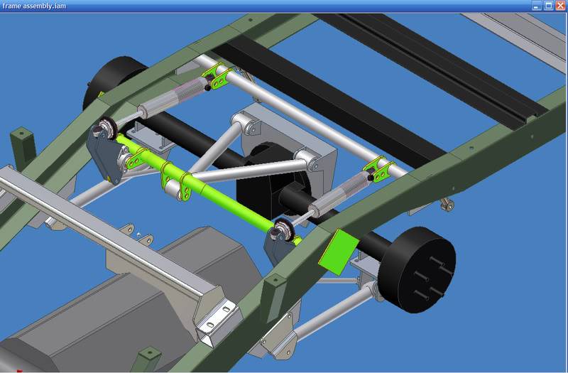
the green one (very bad angle sorry)
i am also looking to get the tabs cut (laser or waterjet)
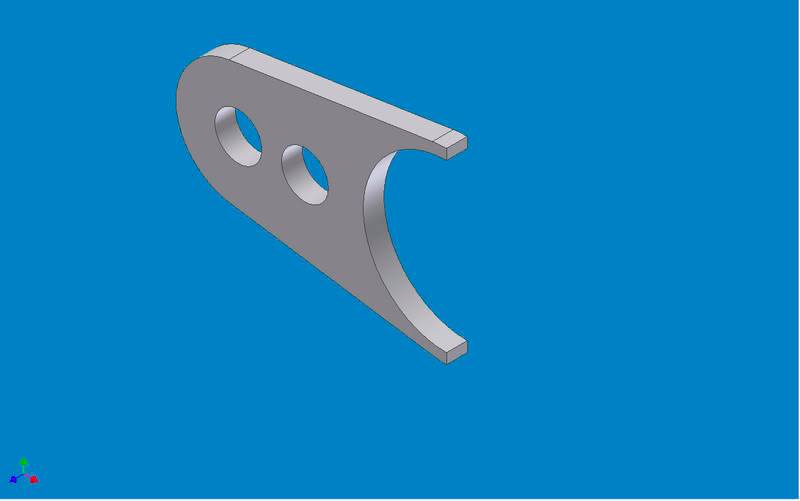
if possible I would like it all welded together for me as well
is there anyone that can help me? or lead me to a place that might be able to?
preferably in the Michigan area to reduce shipping costs.
thanks!
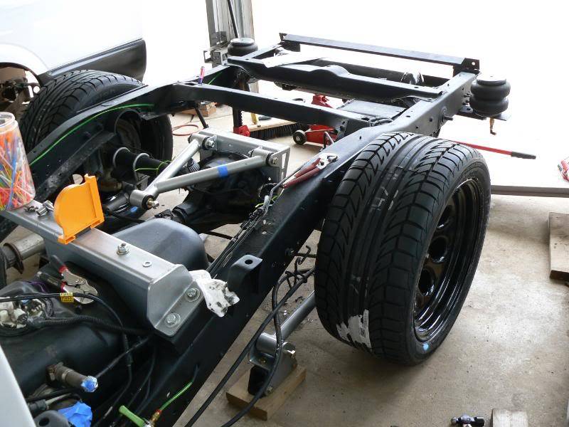
and here is the truck it's going on
-
06-04-2008 #2
Registered User
- Join Date
- Feb 2008
- Posts
- 148
some more accurate updated screen shots
06-04-2008 #3
Registered User
- Join Date
- Jul 2005
- Location
- Marshall , MO
- Posts
- 699
See if you can find a local 4X4 shop that builds rock crawlers or trail trucks. They usually will use heavy wall tubing and have the equipment to bend it.
Brad Shepard
69 Malibu
Marshall, MO
06-04-2008 #4 Registered User
- Join Date
- Sep 2006
- Location
- New York, NY
- Posts
- 458

holy jesus, that crossmember carrys so many loads!!!
1. holds up the car (bending force forwards)
2. centers the rearend (axial force)
3. acceleration (bending force backwards)
4. braking (bending force forwards)
If you find a way to separate it into a coilover crossmember and a link crossmember that would be the best. They could both be straight and not be so stressed.
BTW, is that a bagged tilt bed setup I see?
Jerome
06-04-2008 #5
Registered User
- Join Date
- Jan 2006
- Location
- Oregon
- Posts
- 1,773
What's the minimum bend radius of the cross member shown? My brother has a Pro-Tools HD105 mechanical tubing bender which is good up to 2" with 1/8" wall with a 7" bend radius, but you're not going to do much better than that cold. His 1-1/2" die has a 6" bend radius but is also still limited to 1/8" max wall thickness. Short of a true mandrel bender, you can do some amazing things with them if you don't try to exceed the capabilities of the bender. Most off-road shops will have something similar.
We have a company in Portland that specializes in all types of tube and structural steel bending called Albina (http://www.albinapipebending.com/). You may look around your area and see if there's a similar company where you're located.
Looking at your design, have you considered adding some triangulation to your cross member to support the loads being applied by the center link so that you can get away with thinner, and hence easier to bend, material? I would think a couple of pure links running back from inside the frame rails and tying into the cross member at or below the mounting point for the upper link would greater increase resistance to bending and make everything that much more rigid. Either that or something to tie rearward into the other shock cross member. Anything to help offset the various loads that thing is going to see.
It looks like you've put a lot of thought into it and I've only been looking at it for a couple of minutes, so please take my opinion for what it is...just my opinion. Looks like a fun project. Do you mind if I ask what modeling software you're using?
Tobin
KORE3It's what I does.
06-04-2008 #6
Registered User
- Join Date
- Feb 2008
- Posts
- 148
the only one i know of told me they cannot do it with a drawing, and that they would need the truck there to test and fit.... which is not going to happen.... and that also means that the tolerances will be miles off, as in they cannot bend accurately from a dimensioned drawing. Originally Posted by shep
yes, the major reason is that it has to clear the driveshaft.... and having an aluminum driveshaft, the large diameter shaft needs a lot of room... Originally Posted by jerome
and i thought simplifying it would be nicer to make, and as for forces, i am offsetting concentrated stress by sacrificing weight, hence the 1.5"dia 1/4" wall tube.... which may be overkill, but will make me feel safer.
and yup, that is a tilt bed setup. originally i was doing it just to be 'cool', but now it is needed to be able to fill up my gas tank
currently in that drawing the centerline of the tube is along a 5" radius... which means the inside of the bend is at 4.25" radius. Originally Posted by Apogee
and i dont think it can get much bigger.
which leads me to, if i were to say i can deal with it not being a bent tube, but welded up sections, how will that affect structural strength?
the major reason i havent been able to find a place to do this for me is that i have no way of searching... google does not seem to work too well for me... at least im not using the right combination of search terms.
i have not thought of too much triangulation or extra bracing, as i know my CAD is not totally accurate, hence the reason i am designing everything to be 'bolt-in' for ease of adjustment, and once i am happy with how it sits later on, i will weld a few parts.
another reason is that i have to drive to my school's shop to access a welder, so relying on welding as an initial design wont work for me.
i appreciate any opinion, especially since this is my first major build by myself, and many of you are MUCH more experienced than me in many things.
the software i am using is autodesk inventor.
06-04-2008 #7
Registered User
- Join Date
- Sep 2006
- Location
- New York, NY
- Posts
- 458
how come you can't hook up a filler to the gas door? the tilt bed is really cool though.
I see what you mean with the crossmember clearing the driveshaft. However, unless you are seriously dropped (are you doing a notch on the frame?), the first straight crossmember should be ok?
as for the tabs, you can use a $20 angle grinder and cut-off wheels from harbor freight, and a small drill press to make those brackets...it sucks, but unless you make some friends at a waterjet place, those tabs are going to cost you. Other options are to look at places like Bluetorch Fab, Ballistic Fab, Poly Performance, and other offroad shops, they make lots and lots of tabs pretty cheap. For more vendors, go to pirate 4x4, vendor showcase, suspension forum.
hope that helps...looks like you've put in quite a bit of time designing this system, my only advice is not to make things harder than they actually are...obviously you're the only one that knows what stuff you have to get around, but I know on mine, the crossmembers were all intentionally simple and easy to fabricate. My upper link mounts to the stock gas tank x-member. My lower links mount to an off-the-shelf ladder bar crossmember that I bolted in. I made the mounts for my coilovers, but they just mount to the side of the frame, with a piece of tubing going across to reinforce it. I'm just sayin you might be missing something if it is so hard to fabricate, there's plenty of room under these trucks unless you're slamming them. If your CAD is at ride height, then the height will be pretty similar to mine (my rearend is 3" below the frame), and I fit in pretty long coilovers vertically by having it mounted a few inches below the axle. Not telling you to ditch the bellcrank design, just giving you an example of the easy way out.
Great job so far, I'm lookin forward to seeing this suspension done. Will a stock swaybar work with this, or do you have something up your sleeve?
Jerome
06-05-2008 #8
Registered User
- Join Date
- Feb 2008
- Posts
- 148
i already have the bolt in notch, although i regret this, because the flame flex behind it is ridiculous.... but that is also another reason why i didnt want to mount any coilovers in a 'conventional' method behind the axle. from this bellcrank design, the forces from the spring will only be applied in the longitudinal direction, so the pitch flex and twisting motion of the frame behind the notch will affect the entire suspension package very little, as opposed to 'the easy way out' Originally Posted by jerome
i also originally planned for the package to work without cutting the bedfloor, and that made a few issues trying to get the suspension travel i wanted within that confined height.
my ride height is aimed to be 6 or 7 inches of ground clearance with my 275/40/17 tires. compared to the 4 inches of clearance i was running before, it will feel like i am miles high
for the tabs, i do have access to a manual mill, so i can easily make them on that... although making 10 of them will take forever, and i also need to make 4 bellcrank walls.
if i learn to use the cnc mill, i might do it on that, but that will also take a long time..
i relocated the gas tank forwards almost a foot, so the filler neck will not line up with the gas door.
i dont think i can do a straight crossmember without seriously changing my design, because the driveshaft, bedfloor,and bellcranks create a lot of confinement
as of now, i will be using the zq8 rear ('stock') swaybar, but i have not run any numbers, and i have a feeling it's way too small.
but then again, i'm pretty sure the front 'stock' zq8 swaybar is also too small, so making new ones will be a project for another time.
having bellcranks, i will have much freedom in designing a rear swaybar.
thanks for the tips! but i think its too late now to ditch the major design
06-05-2008 #9
Registered User
- Join Date
- Sep 2006
- Location
- New York, NY
- Posts
- 458
you can hook up a flexible hose filler for gas i'm pretty sure
06-05-2008 #10 Registered User
- Join Date
- Apr 2005
- Location
- dayton, oh
- Posts
- 952
for tabs and brackets:
http://www.ballisticfabrication.com/...Tabs_c_11.html
so, maybe I'm not understanding something here. i'm looking at your bellcrank design, and it looks like the links from the axle are only angled 30* from the ground? if the axle moves vertically, that will only slightly push forward on the bellcrank. it seems like the leverage on the coilovers will be very slight, and if the axle moves up much, the link will be almost horizontal, and it will have no leverage at all.... ?
awesome project, though.
06-05-2008 #11
Registered User
- Join Date
- Feb 2008
- Posts
- 148
dave, i agree the pushrods are very 'inefficient', and the bellcrank will be taking some major forces, but with that bellcrank geometry i have been able to get almost a 1:1 wheel rate. obviously changing the geometry of the bellcrank will allow me to go in either direction, and also control the progressivity (?) of the rates.
as of now, the design is very close to linear, with a slight progression of higher rate the deeper in bump it goes.
06-06-2008 #12 Registered User
- Join Date
- Feb 2006
- Location
- s.f. east bay california
- Posts
- 209
something looks off to me
I'll start by saying that I am not a expert at designing suspensions. But I have done a lot of research in preparation for my own chassis I am building. It looks to me like your cantilever will not have much actuation from the link to the axle. It may just be the angle of the pics but to me it looks like the lower link between the axle and the cantilever pivot is too parallel to give it much movement tot he shock and spring. So one because of the very layed down approach of the link to the axle you will have to run a spring that is much stronger than if running it more vertical. Another thing is that as the axle moves up in its path of movement, and the pivot link rotates around its pivot. The amount of actuation will decrease as it moves through their range of motion. As the link on the axle moves up and the link on the pivot block moves forward the angle at witch the link bar is in relation to the axle link and the pivot link become more and more parallel and there will be less and less forward pressure on the pivot link and will stop compressing the shock and spring.
I did a quick search to give an example of what a more efficient example would be and still fit your space confinement with a little adjustment.

See how the link from the axle to the pivot block is nearly vertical. When designing a cantilever suspension the link between the axle and the pivot mechanism has to be thought of as the shock and spring. You would not lay a straight coil over shock as parallel to the ground as your lower link would you, y because it would not work very well. A cantilever allows you to lay the shock and spring down but you still need a vertical link from the axle to transfer the axles vertical movement into a horizontal one.
Like I said it may just be the angel of the pics u posted but to me you dont have an addaquit vertical link to transfer the axles vertical movement to the pivot block.
Looking at your pics theres a big open space behind the axle. If you dont have something already planned for that space u mite consider turning the shocks and spring perpendicular to the frame like this.
I know its not the best example of packaging for your application but the concept is the same. The shocks dont know forward back side to side. As long as the force is coming from a vertical plane into the pivot mechanism there happy and will work just fine.
Again, not an expert or anything, just done a lot of homework and have built many smaller versions for off road and on road r/c cars.
Hope I was able to explain things in a way everyone could understand, or not make an ass of myself. I could be totally off but I can only go by what I am looking at (static pictures) U may have a suspension modeler like I used too that you can plug all the dimensions into and watch it work. I dont know but good luck with your project.Dog will Hunt
06-06-2008 #13
Registered User
- Join Date
- Sep 2006
- Location
- New York, NY
- Posts
- 458
oh man, I completely missed it...I thought your bellcrank hadn't been drawn in yet, your coilover was fixed at the front, and those chrome links were the links to your bellcrank
quick rouch calculation:
3 inches of rearend travel
link looks like about 30 degrees from horizontal
bellcrank looks like it magnifies travel by a factor of almost 2
3 inches of vertical travel at rearend * sin(30) = 1.5 travel at link
1.5 travel at link * 2 = 3 inches travel at coilover
It seems to work on paper. However, here's some problems I can think of with a non-vertical link transferring load to the bellcrank.
-As your rearend travels upwards, the angle goes towards zero, giving travel*sin(0)=0 travel in the coilover.
-Pinion angle looks like it decreases in upwards travel of the rearend. This will pull back on the coilover rod, while upwards travel will push on the coilover rod. These two counteract each other and you don't get full effect.
-Rearend rotates in an arc, getting further from the bellcrank in upwards travel, also partially counteracting the effect of "pure vertical travel"
-Anti squat traditionally comes from reaction of rearend against tire torque. This causes compression in the lower links and tension in the upper links. With the right arrangement of links (usually lowers pointed up and uppers pointed down) this causes an upwards force on the chassis. However, with your design you introduce the coilovers as an absorbing force also. I would be very hesitant to do that, as the coilovers would not absorb much of the initial shock of the acceleration (because of shock damping), pushing the car up like in antisquat transferred through a suspension member, then it would absorb it after the transient damping period, lower the rear of the car back down, and possibly oscillate between those two modes (wheel hop).
Again, your design, but my opinion is...instead of dealing with all this stuff, make your coilover rod vertically transfer force to a bellcrank. That would make life alot easier.
Please correct me if I'm wrong...like trackrat said, you probably have worked all of this out, and it actually works.
Also, just forgetting the coilovers for one second, with the parallel lower link design, you're roll axis is gonna be the side view of the lower link. I assume they are pointing up (to get some antisquat), so now you've got roll oversteer, which may be nice in autocross, but won't be so nice at 90MPH. I'd advise you to converge the lower links a bit. That way, you're roll axis is drawn ( in side view) from the wishbone attachment point at the chassis to the point of convergence of the lower links. This can create a neutral or understeer condition while still maintaining the antisquat.
06-06-2008 #14
Registered User
- Join Date
- Feb 2008
- Posts
- 148
i agree totally that this looks bad... lol
but on paper (cad), it works well.
i have many ways of adjustment, so if this plan does not work, i can 'fix' the problem relatively easily.
and as for roll oversteer etc, i regret getting a 'kit' with the wishbone to work around. originally i had thought this would simplify matters a lot, but turns out its limiting everything...
jerome, im still very fuzzy on the dynamics of a solid axle suspension, so i can use all the help i can get.
you are saying i should move the inboard lower perches closer towards the longitudinal centerline of the truck?
as for your comments on the pinion rotation affecting the pushrods, im not sure if you caught that the pushrod is mounted on the same axis as the lower link outboard pivots, so axle rotation can be 'ignored'
i can look at the motion of the suspension 'purely' with just the lower link bars.
here is an earlier model, but you can see how it works on paper.
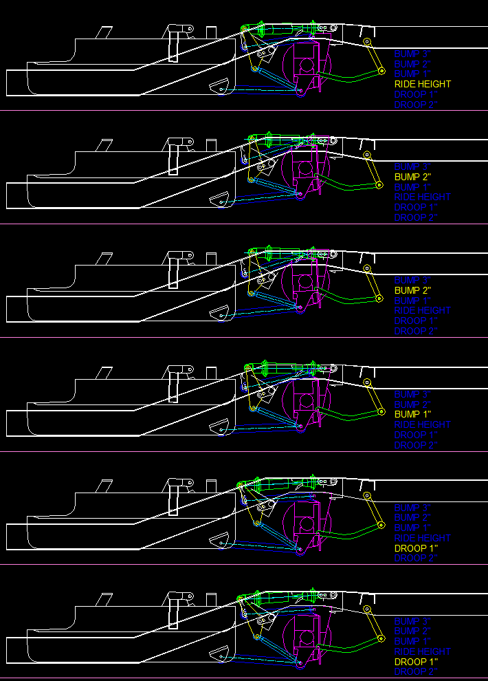
i would have to say from the angles i showed in the screenshots, the pushrod angle might seem to be worse than it is, although i totally agree it should be more vertical.
06-06-2008 #15
Registered User
- Join Date
- Sep 2006
- Location
- New York, NY
- Posts
- 458
yeah, use a crossmember to mount the frame-side of you lower links more inboard. Have you calculated the anti-squat you're getting yet?
Looks like there's no way to change lower link angle without changing ride height, and that will be a problem if you're trying to optimize for anti-squat and roll steer.
I have the MATLAB file from when I calculated all my stuff, you can input the numbers and see how they change roll axis, antisquat etc. No way to show bump, droop, roll, except for changing the inputs though. If you have MATLAB or access to it, I'll find it and post it. No knowledge of MATLAB necessary, it'll just pop the answers for you.
Jerome
06-06-2008 #16
Registered User
- Join Date
- Feb 2008
- Posts
- 148
yea, i have matlab at school so that would be awesome!
i drew things wrong in cad (leaf spring perches are not parallel to the ground stock. oops)
so my angles are outta whack now anyways....
sucks, but not much i can do about it at this point.
i havent done nearly the calculations i wanted to, due to lack of knowledge and time, so i based most things on what others have done, and seemed to work + a big safety factor.
mounting the lower perches inboard would be a pretty simple fix later down the road.. i just need to get this truck running first. even to get to the machine shop im borrowing mom's van... and that just wont work...
i need to get this suspension built to work 'for now', then i will remeasure everything and update the CAD to be correct, then start thinking of modifications to improve on it.
bad way to do it, but not much i can do about it now, as this is my daily driver.
im glad i am keeping everything 'bolt-on'
so i can change out components easily. i can build a full cross member, and swap it out in a day.
06-06-2008 #17
Registered User
- Join Date
- Sep 2006
- Location
- New York, NY
- Posts
- 458
%x=out
%y=forward
%z=height
%a=axle f=frame
%l=lower u=upper
%INPUTS
cgh=24; %center of gravity height
wb=109; %wheelbase
axh=13; %axle height
al=[-22.25 22.25;0 0;8 8]; %lower links axle coordinates
au=[13;0;18]; %upper link axle coordinates
fl=[-8.5 8.5;28 28;10.5 10.5]; %lower links frame coordinates
fu=[13;13;17]; %upper link frame coordinates
pb=[0;-6;13]; %panhard coordinates
mc=3000; %mass of car
mr=250; %mass of rearend unit
axr=4.10; %rearend gear ratio
%ANALYSIS
mu=(fu(3)-au(3))/(fu(2)-au(2)); %slope of uppers
ml=(fl(3,1)-al(3,1))/(fl(2,1)-al(2,1)); %slope of lowers
in=[-mu 1;-ml 1]\[au(3)-mu*al(2);al(3,1)-ml*al(2,1)]; %intersection
SVSA=in(1) %side view swing arm
antisquat=(in(2)/in(1))/(cgh/wb)*100 %antisquat percentage
pvcy=(fl(2,1)-al(2,1))*al(1,2)/(al(1,2)-fl(1,2)); %plan view convergence y coordinate
pvcz=(fl(3,1)-al(3,1))*pvcy/(fl(2,1)-al(2,1))+al(3,1) %plan view convergence z coordinate
offset=(au(3)/(al(3,1))*axh*mc)/(axr*(mc-mr)*(cgh/wb+abs((au(3)-fu(3))/(fu(2)-au(2))))) %third link offset necessary for 100% cancellation
conv_angle=atand((fl(1,1)-al(1,1))/(fl(2,1)-al(2,1)))
%PLOTS
subplot(2,1,1) %plan view
plot([al(1,1),fl(1,1)],[al(2,1),fl(2,1)],'b') %lower driver
hold on
plot([al(1,2),fl(1,2)],[al(2,2),fl(2,2)],'r') %lower passenger
plot([au(1),fu(1)],[au(2),fu(2)],'k') %upper
title('Plan View (top is front)')
subplot(2,1,2) %side view
plot([al(2,2),fl(2,2)],[al(3,2),fl(3,2)],'r') %lower arms (uses passenger numbers)
hold on
plot([au(2),fu(2)],[au(3),fu(3)],'k') %upper arm
plot([al(2,2),wb],[0,cgh],'c') %anti-squat line
plot([fu(2),in(1)],[fu(3),in(2)],':k') %upper extension to intersection
plot([fl(2,1),in(1)],[fl(3,1),in(2)],':r') %lower extension to intersection
plot([pb(2),pvcy],[pb(3),pvcz],'m') %roll axis
th=linspace(0,2*pi);
plot(13*sin(th),13+13*cos(th))
plot(3.25*sin(th),13+3.25*cos(th))
title('Side View (right is front)')
axis([subplot(211),subplot(212)],'equal')
For anyone not familiar with matlab, anything after a "%" is just comments. Calculations will appear unless a ";" is added after the calculation, so to see the result of a calculation, remove the ";"
Paste the code into Matlab and run it, and you get this plot:

Important graph is at bottom
lower control arm & upper control arm imaginary dotted line extension, intersection of lines if above blue line(antisquat line) means greater than 100% antisquat, lower means less.
purple line is roll axis, downward slope means roll understeer, upwards means roll oversteer. On mine, it is defined by PHB height on left of screen and intersection point of lower control arms.
disregard stuff about offset, that was to tell me how far to offset the upper arm to cancel driveshaft torque
optimization:
antisquat-opinions differ, i was shooting for roughly 90-100% throughout the travel range, once you have ride-height antisquat where you want it, play with control arm length ratios to get it to remain constant
roll steer-shoot for neutral or slight understeer, and see if you can keep it from going to oversteer during the whole travel range
SVSA (side view swing arm) length-longer is better to prevent brake hop, shoot for greater than 45-50 inches
That's about it...
Jerome
06-06-2008 #18
Registered User
- Join Date
- Feb 2006
- Location
- s.f. east bay california
- Posts
- 209
That motion file is a big help in understanding it better. Those pics had me all screwed up. but now another question, what is linked to the axle from the read in green and yellow?. Looks like it could possably be an anti roll bar of some kind but have never seen one mounted so that it could swing before.
Dog will Hunt
06-07-2008 #19
Registered User
- Join Date
- Feb 2008
- Posts
- 148
thanks jerome!
i will try playing around with that the next chance i get..
any chance you have a file for maple instead? i have that on this computer
trackrat, yup, thats the rear arb
its the 'stock' one on the s-series.
mounted to the axle and the endlinks are mounted to the frame.

 Reply With Quote


