


Results 1 to 20 of 22
Thread: 1989 Chevrolet C1500
Threaded View


-
11-12-2024 #1
 Registered User
- Join Date
- Jun 2019
- Location
- Nashville, TN
- Posts
- 24

1989 Chevrolet C1500
Hey folks,
My name is Jimmy King, and I am here to document the build of my 1989 C1500. The truck is about finished and over the next few posts I’m going to write in high detail about the truck, my build process and fabrication, and why I did things the way I did. The goal with this truck is to run autocross and some road course stuff this next year.
To give some background on myself, I’ve been building cars in some capacity for roughly 15 years. My dad and brother are great influences in that and my passion started in more traditional hot rods as that’s what they were into. Fast forward through college where I received my degree in mechanical engineering, I became more interested in racing and what that entails. Engineering school set me up with some great tools and the knowledge to look at the components of cars in a more objective way and design them as such.
I hope this post will spark some good discussion and will help me improve when moving into the development phase of this truck and chassis.
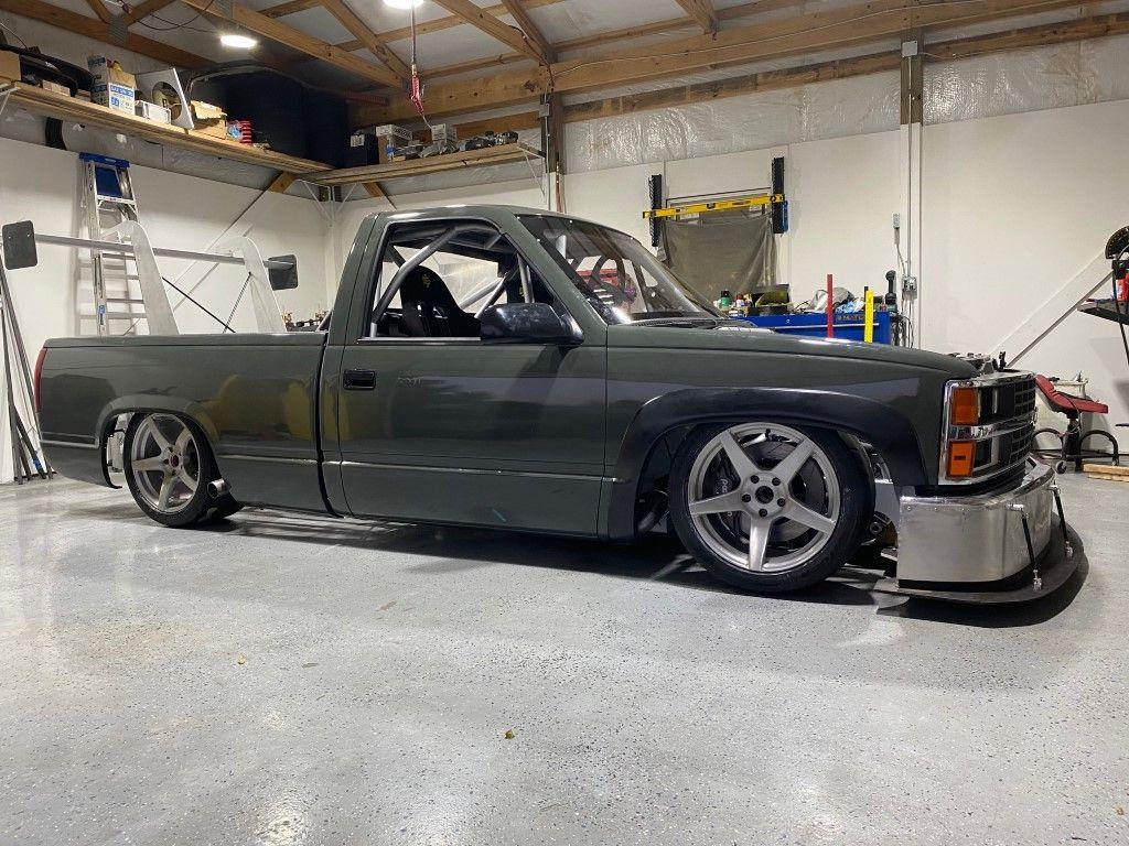
PART ONE: Front Chassis, Suspension, and Brakes
I took a lot of inspiration looking at TA2 and circle track cars, and there is a big crossover between the two as a few manufacturers build both. In particular, I found a brochure for the Howe TA2 chassis’ and they had a color-coded picture that labeled all the tube sizes on the chassis. Howe, at some point, worked with GM on some destructive testing of their chassis which sold me on the design. There’s a technical paper floating out there about this test.
I had worked in CAD for a few months to get the design correct. A lot of simulation with suspension/steering geometry and tire clearance. Running a 345 proved to be a decent challenge. There are compromises to everything, and at some point, I needed to start building.
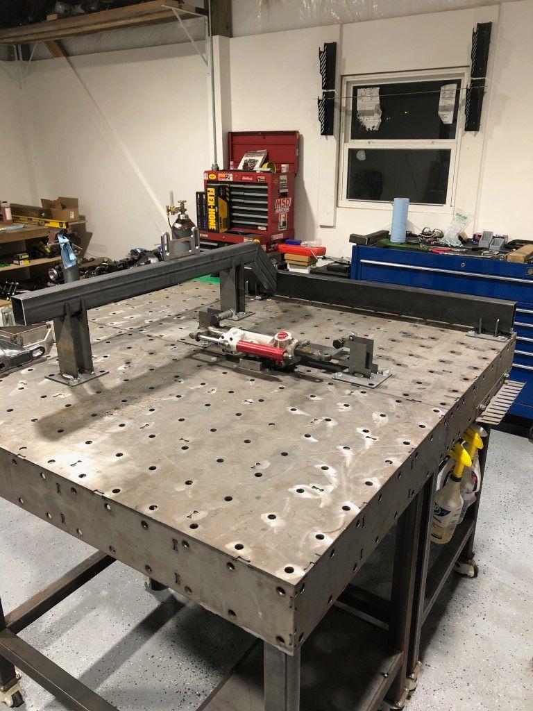
I designed around a used Woodward Steering rack that I found for a few hundred dollars online. I don’t find any particular problems with steering boxes, but if I was building a chassis from scratch, this made the most sense. I can also swap parts to achieve a wide range of steering ratios.
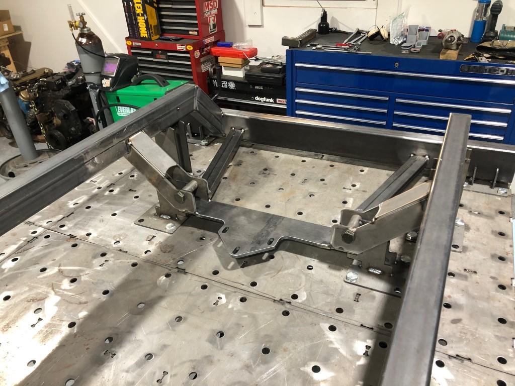
I built many fixtures to place all the tubes and maintain accuracy. I love building this way because components only fit one way. The crossmember closest to top of this photo eventually had a chunk cut from the center to accommodate the engine and transmission. I kept it intact until after the entire chassis was welded together to reduce warping.
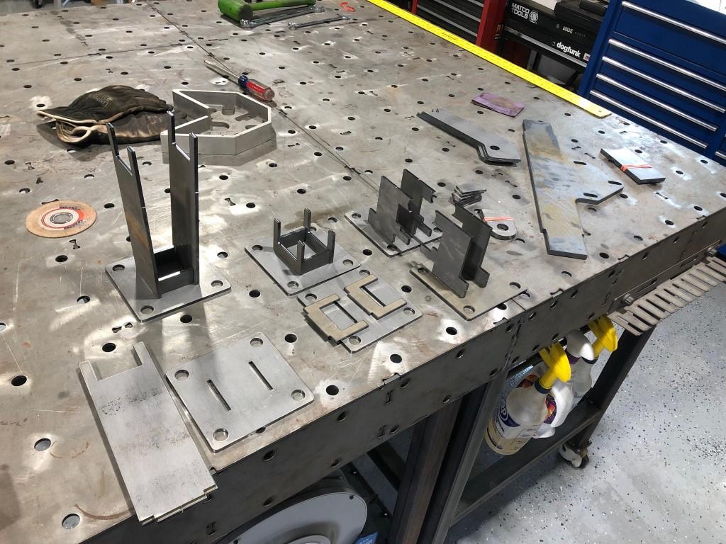
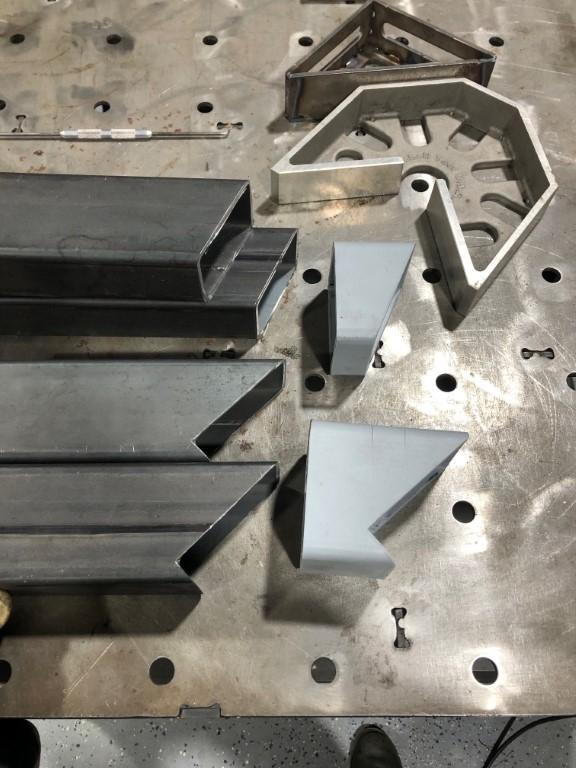
I 3D printed guides to mark out the coped profiles of each tube. This saved a lot of time as I could be working on other things while the part printed. These guides also took the guess work out once I started cutting.
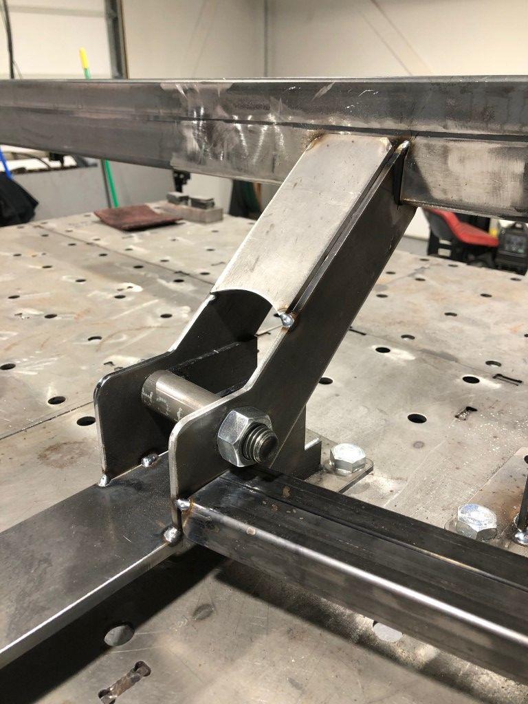
This is the passenger side where the lower control mounts. The front most plate would later be trimmed slightly to clear the fittings on the dry sump oil pump.
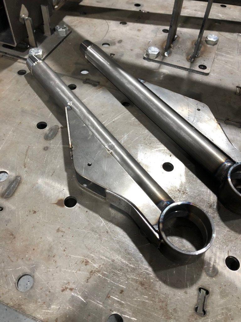
These lower control arms are all chromoly. I bought the ball joint cups to fit the K727 Chrysler ball joints. This will be an area for tuning as there are several companies that make this style ball joint in various stud lengths.
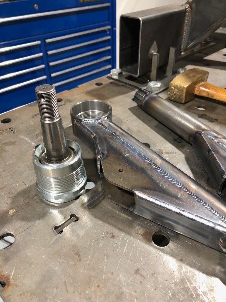
The small hole would later be drilled to accept a ¾" bolt. The lower control arm assembly is a trailing arm style, where a solid rod EYE is placed between the plates on the arm, and a rod end mounts back at the chassis.
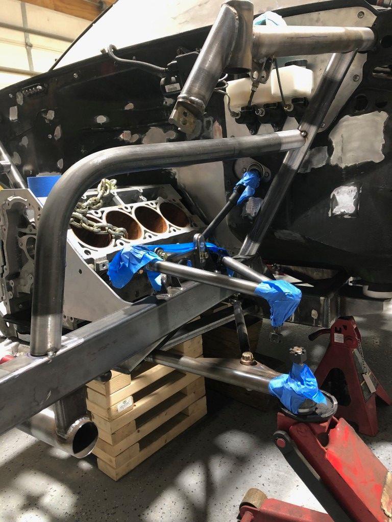
This picture jumps a way ahead, but it illustrates how the lower control arm assembly resides on the chassis.
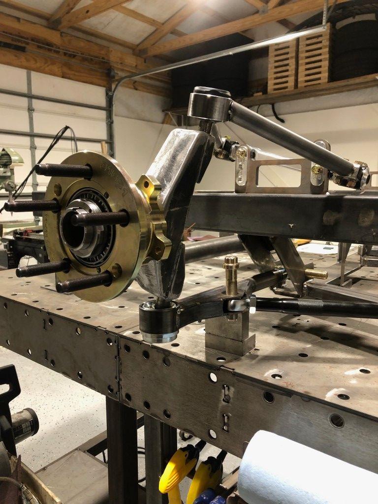
This was an early mockup with upper controls arms that I had built. Later on, I had some clearance issues and bought some upper control arms that are off the shelf and come in many different geometries. The upright is the TA2 upright from Port City Racecars. They run 2” bearings on both the inside and outside. I used Coleman hubs in 5x4.75”. The pin is so big that I don’t think pad knockback will be an issue. (NOTE: the rod EYE is missing from the trailing arm. I didn’t have one yet so a rod end sits in place.)
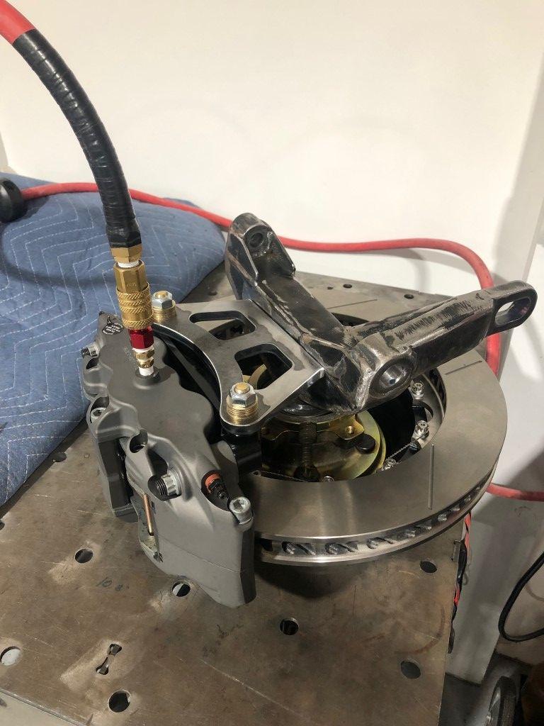
I purchased the uprights less the caliper brackets as circle track cars run a fairly small front disc. I 3D printed an initial bracket prototype, confirmed fitment, then sent the file to the laser cutter. It is 3/8” thick. I adapted my compressor hose to the caliper in order to clamp the disc and ensure a robust placement while I welded.
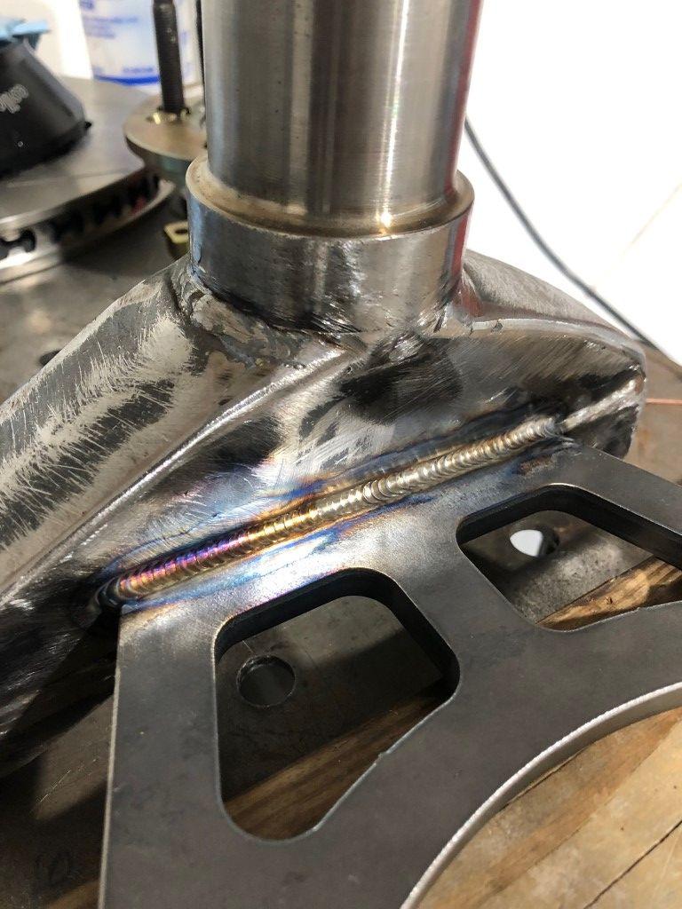
I did two passes per side as the material is thick and wanted to ensure I had a good fillet in there. Gussets were added later.
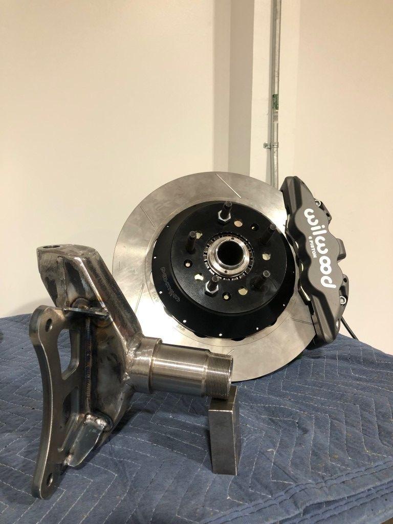
Final product.
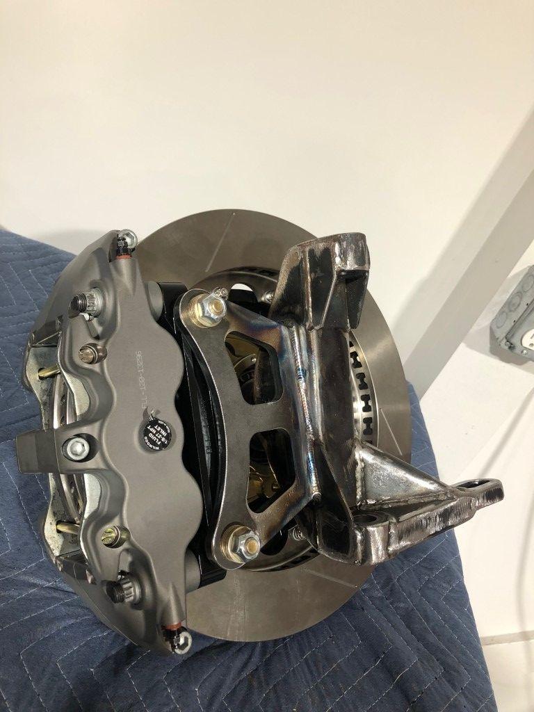
I leave it at that for now. Next up will be the remaining sections of the chassis and rear suspension. Thank you for reading.
Jimmy
-

 Reply With Quote


