

Results 1 to 8 of 8
-
07-18-2015 #1

 Registered User
- Join Date
- Mar 2013
- Location
- Boise ID
- Posts
- 97

Second Gen Quadralink Modification
Need some advice, thanks in advance!
FIRST.....I'm ABSOULUTELY not complaining about anything DSE has done here, everything including their tech support is first class.
I've installed all four mounts for the upper and lower links. While test fitting the stock spring pocket mounts (see first pic), I looked to clean it up as well as allow me to overcome some of the factory frame inaccuracies and insure the links were exactly centered and square to the rear end. I spoke to DSE about the 1/4" out of square the links would be using the stock spring pockets and they thought this was at the upper limit but acceptable. Frankly, just flexing the rubber bushings would fix that amount.
Truth be told, I don't know why the spring pockets bug me, they just do.
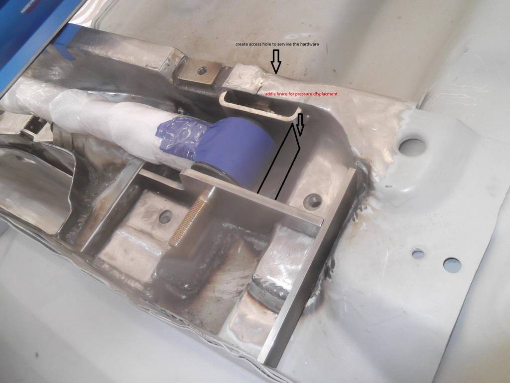
The attached pics are my solution. I've only tacked them in place so far as I was looking for you guys to shoot holes in my design. Please....I'm looking for reasons NOT to do this so please swing away! Ha!
For sure weld strength is crucial, but beyond that it looks to me this should be at least as strong as the spring pockets.
The location of the bolt for the link is exactly in the same place as it would be with the pocket.
Thanks
John
-
07-18-2015 #2 Registered User
- Join Date
- Nov 2008
- Location
- Lawrenceburg, TN
- Posts
- 4,098
how do you service the bolt? is there an access hole on the other side?....I do like it...I hate spacers and the leaf pockets, but thats what makes the hardware serviceable
07-18-2015 #3
Registered User
- Join Date
- Mar 2013
- Location
- Boise ID
- Posts
- 97
Yes, there is a hole through to the other side of the frame. If you look at my build thread, you can see how I did that. Glad somebody else doesn't like the pockets!! Thanks!
07-18-2015 #4
Registered User
- Join Date
- Nov 2008
- Location
- Lawrenceburg, TN
- Posts
- 4,098
07-18-2015 #5
Registered User
- Join Date
- May 2013
- Location
- Colton Ca.
- Posts
- 623
It looks like you dropped the arm down about 1/2"or so, is that going to cause interference in the arms travel once the suspension is compressed or the cars lowered? I like it tho.
Ahmad B.
09-30-2015 #6
Registered User
- Join Date
- Mar 2013
- Location
- Boise ID
- Posts
- 97
Hey guys, sorry for the delay in getting back. Appreciate the advice. Yes, I had already created the access hole, actually DSE did this by using an existing hole in the frame. That access hole is oblong and not exactly in the ideal location for access to the nut (the DSE setup had the bolt coming in from the opposite site as my mod's). Agreed, there shouldn't really be a huge need to have access here except for "bolt check" purposes. I added the access hole and 2" round sleeve....I guess just because I could!
I did take Rod's advice and added that brace but did it using a piece of angle, I also added another brace on the interior side (under the link).
Ahmad, you are correct, it does look like I lowered the bar a lot and I agree that would cause interference with the chassis, however, that pic is a little deceiving. Actually I did inadvertently lower it about 3/16" because I used a set of spring pockets I purchased from Classic Industries to locate the center hole in my assembly but when I checked them against a set of stock ones, their hole was about 3/16" lower than the stock ones. I made a mock up the rear end with the shock fully compressed and checked that it didn't hit the frame...it didn't. Pic's attached.
Still need to do some clean up of the welds and I know some of them look bulky but In some cases I was overlapping my pieces with the existing DSE parts and wanted to insure connection the chassis.
I did cover the frame mount with some sheet metal, just to increase the cleanliness of the look. Yes, I probably didn't do a good job here in keeping the overall build on a strict diet but at least the weight is low. Once I started down this path....I couldn't stop myself. I'm sure you can relate!!
On that note, I wasn't really sure how much additional bracing came from the angle bracket that was provided to be installed between the upper link assembly and the frame (pic with my finger), it only had three plug welds and one was essentially on a piece of sheet metal. I fabbed up a bit of a stouter bracket, again...I know I added some weight but it seemed to me that if a brace was necessary in this location...it should be as strong as possible.
Appreciate any further input.
Cheers!
09-30-2015 #7 Registered User
- Join Date
- Nov 2006
- Location
- Ma.
- Posts
- 5,560
Nice work!
Wayne
Car FINALLY home !!!!!! lol
Project FNQUIK https://www.pro-touring.com/showthre...ghlight=FNQUIK
01-03-2016 #8
Registered User
- Join Date
- Apr 2010
- Posts
- 95
Agreed. I love this build!!!

 Reply With Quote