


Results 1 to 20 of 132
Hybrid View


-
07-18-2015 #1

 Registered User
- Join Date
- Sep 2010
- Location
- corona,ca.
- Posts
- 1,130

Dr.G,question.
How do you keep your work bench from moving while using your bender?
It looks like you have casters on there.
Keep up the good work,im loving the fab!
Phil
72 chevelle.
-
07-18-2015 #2 Starting The Transformation
- Join Date
- Feb 2010
- Location
- El Segundo, CA
- Posts
- 268
Good question. I used what they call "self-leveling casters". For mine you have to turn a little dial on the caster and it lowers a big rubber foot down onto the floor, taking weight off of the caster. That keeps the work bench from moving around. I have to have the thing on wheels since my garage is not big and I have to move stuff around depending on the project at hand. Gustave Originally Posted by chevelletiger

07-26-2015 #3
Starting The Transformation
- Join Date
- Feb 2010
- Location
- El Segundo, CA
- Posts
- 268
I finished modifying the cab floor to accommodate the new brake pedal and provide a bit more forward leg room:
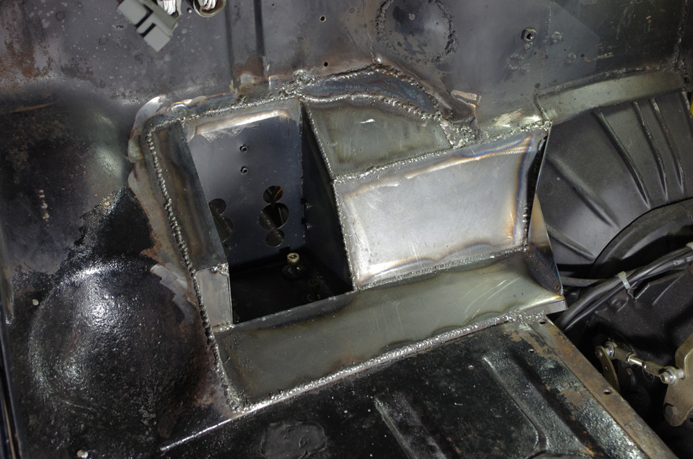
I will have to modify the tranny cover to match this new floor. And I will build a bottom hinged throttle pedal to go on the right once I get the seats back in so I can test fit everything. The C-shaped patch along the top of the new metal was a repair. I had a perfect fit for a butt joint along the top, but a previous builder had sanded the old sheet metal so thin (during a firewall reshape) that when I went to tack in the new metal, the old metal just vaporized. So I was left with a 1/4" gap to contend with. After trying to fill it with MIG I finally realized it better to just put a patch over it. When I get the cab off during my new frame construction (first half of next year hopefully) then I can get proper access to try and fix this area properly. Right now with the engine in the way it is just too difficult.
Here is the completed pedestal I built to mount the brake pedal cluster to the frame:
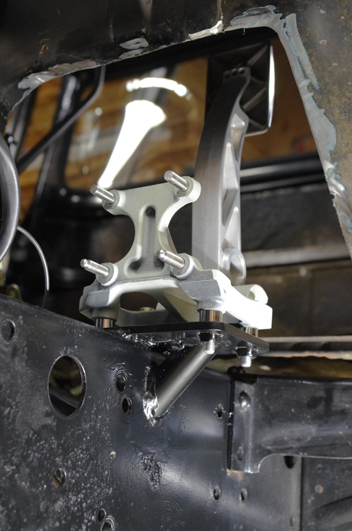
This should be plenty stiff and the new floor will wrap around the brake pedal, with the master cylinders outside in the engine bay. That part turned out just how I'd hoped.
Here is the start of the new seat mounting base I made:
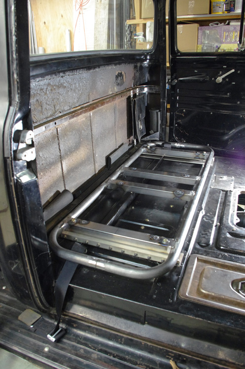
I showed pics of me bending this tubing earlier. It's 1.5" 0.095 round with 0.065 rectangular. I have a habit of overbuilding stuff. If I did this again I'd make the whole thing out of 0.065
The seat platform bolts to aluminum adapter brackets, which pick up the original 8 threaded holes in the cab floor. The seat sliders will bolt to this platform. I welded little cylindrical tubes through the rectangular sections so that they would not crush when tightening the bolts for mounting to the cab and the seats.
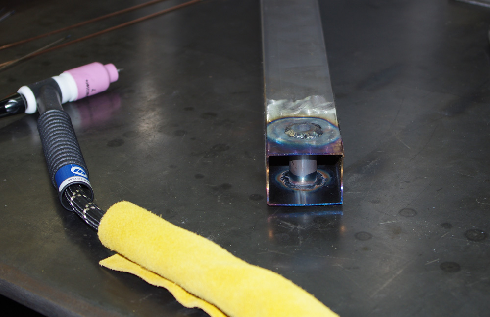
As you can tell I am still a total beginner TIG welder. But when I finish a weld, I look at it and ask myself it I will bet my life on it. If the answer is yes, then I move on. It's more the aesthetics and consistency of the welds I have trouble with. But I could sit there and weld practice coupons all day and not get the kind of practice I'm getting on all the various welding involved with these projects. So much variety. Different thicknesses, round to square, round to round etc...
I've also mostly finished the first lower control arm. Here is a pic of it compared to the old control arm, which was made by a previous builder.
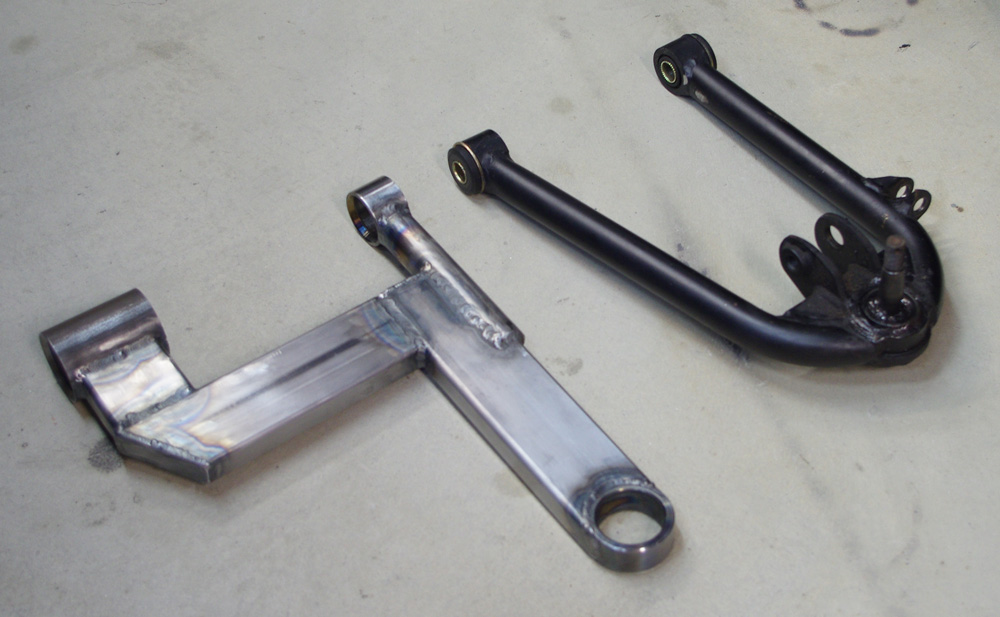
Surprisingly the new control arm weighs 6 lbs and the old one weighs 7 lbs. Though the new one still needs tabs for mounting the shock and sway bar.
The principle with this control arm design is to have a very direct path from the outer ball joint to the inner pivot point. To take up cornering loads with minimal deflection. Then the rear pivot point will be a rubber bushing. This allows the front wheels to move backwards a tad when hitting bumps, which is important for ride quality. I basically copied the principle from BMW, who used the same concept on the E30, E36 and E46 chassis 3-series cars. The only caveat is that the BMW's used McPherson struts, so as the lower out balljoint moved back, there was only a small change in caster, as in under braking. For my implementation there will be more caster wind-off during braking. We'll see how it goes, it is king of an experiment, and having to adapt it to my existing frame entailed certain compromises.
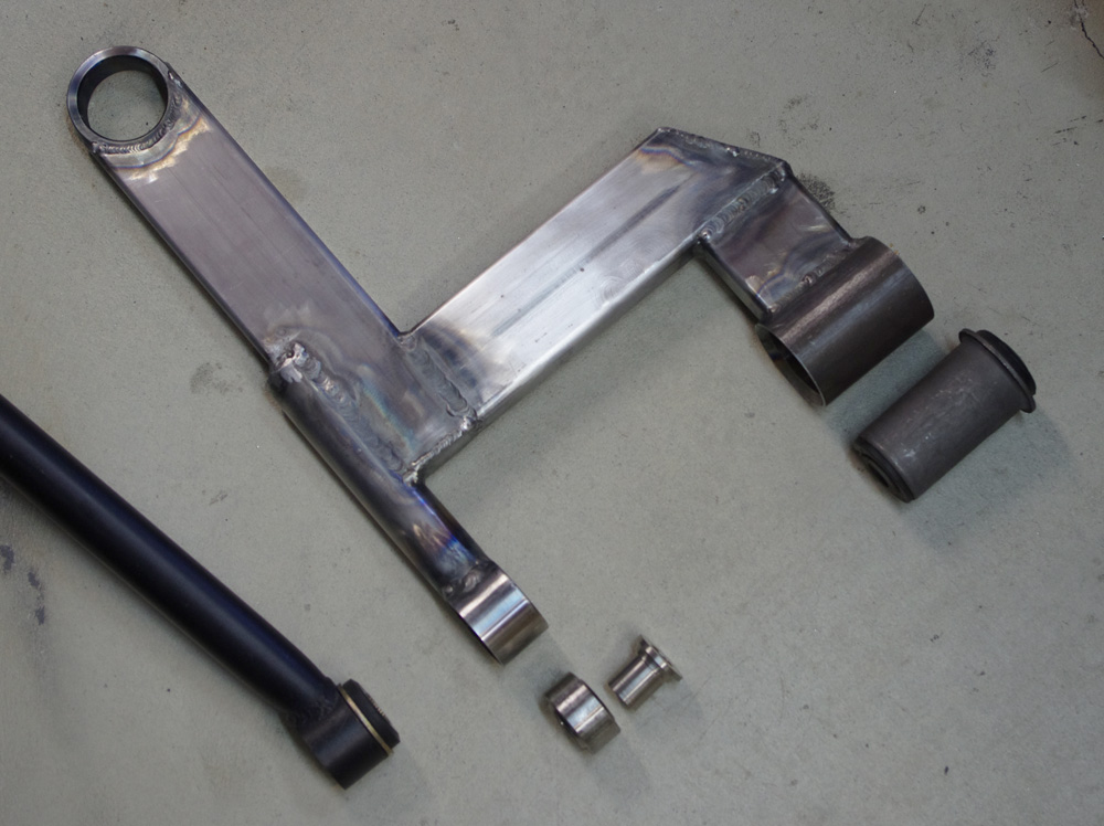
The front pivot is a regular spherical bearing to help deal with camber change when cornering.
Gustave
08-12-2015 #4
Starting The Transformation
- Join Date
- Feb 2010
- Location
- El Segundo, CA
- Posts
- 268
Some progress pics...
Since I am increasing caster, it seemed reasonable that the load on the power steering would be increased. So I've added a power steering fluid cooler. Here is a pic of the steel shroud I fab'd up to direct air to the Earl's cooler:
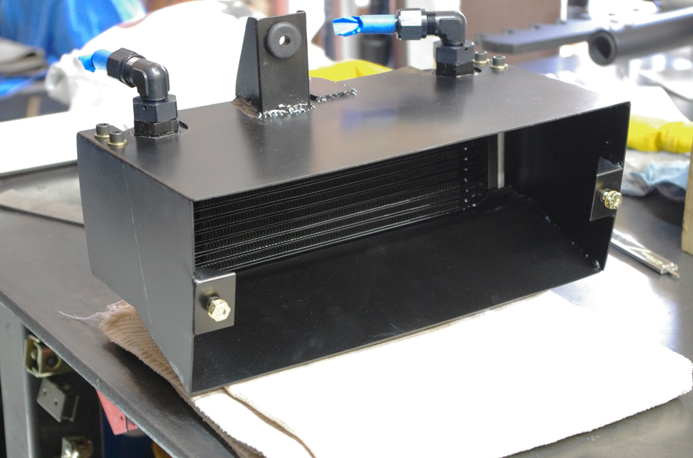
The cooler is situated behind what Ford calls the "gravel pan". I am busy now plumbing it into the pump and rack.
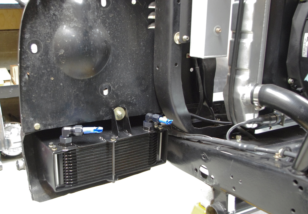
Air is directed to the cooler via holes in the gravel pan:
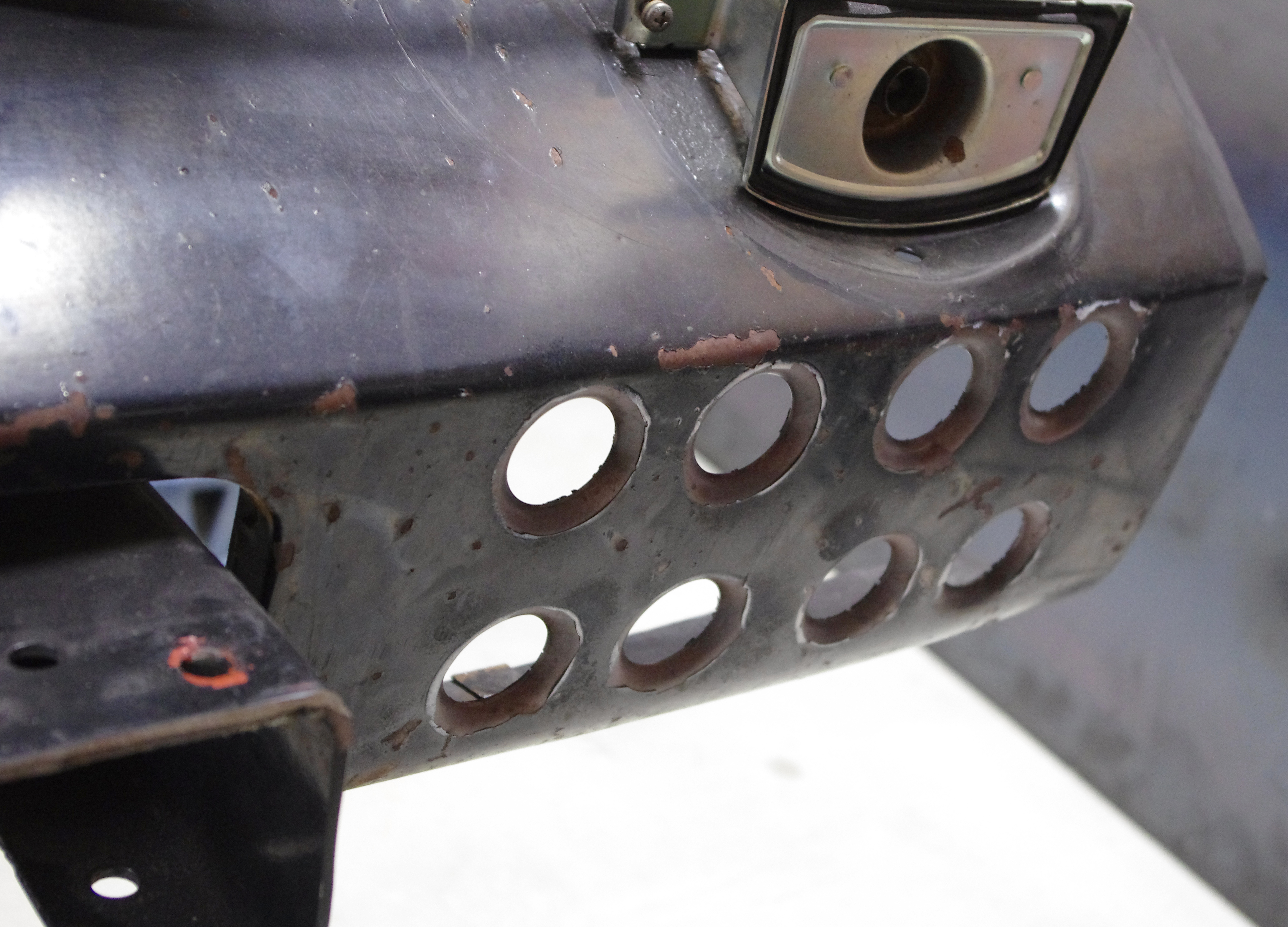
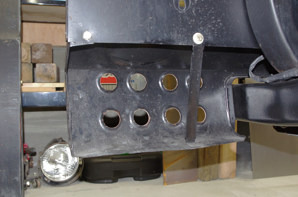
In terms of maximizing air flow to the cooler, this is not optimum, but not bad. The bumper will get in the way to some extent, and I'm not ready yet to punch holes in that like Rob did.
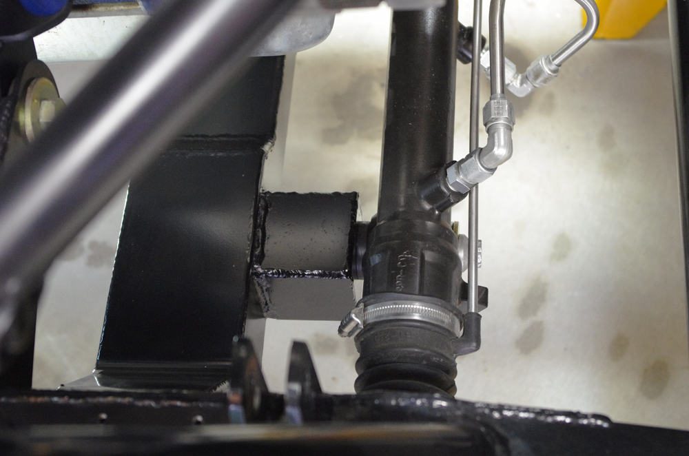
Because my new control arms push the front wheels forward both to increase the wheelbase 1" and some more to increase caster, I had to move the rack forward and up. This was a bitch to figure out. I think I got it close, but ultimately I will need to measure the bump steer to know for sure.
The original rack was mounted on these pylons:
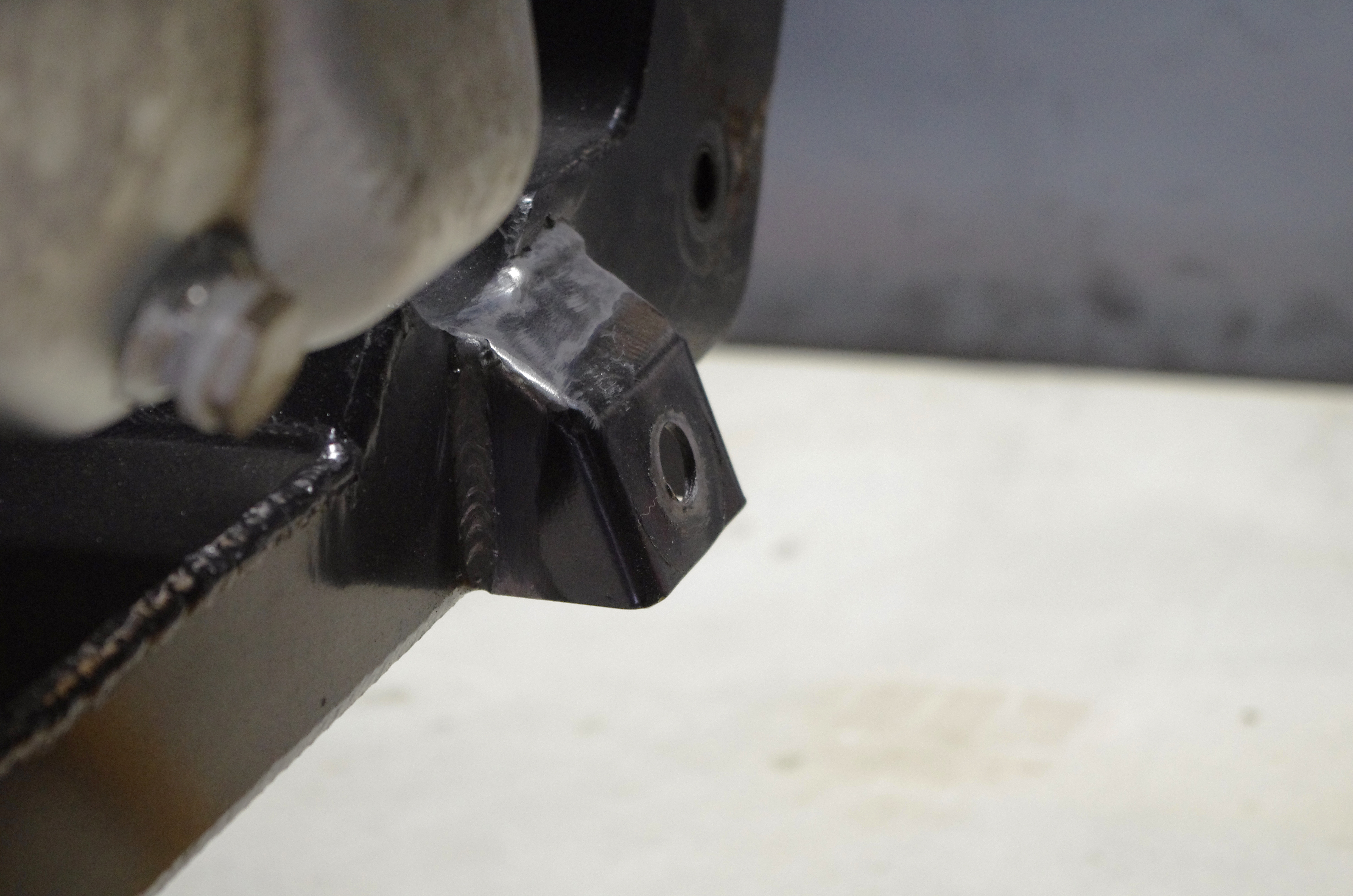
The easiest way I could think of to make new mounts was to enclose these pylons with new bigger pylons. Here they are welded up on the bench:
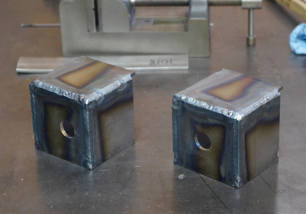
And here they are welded onto the (wimpy) subframe:
I've also finished the lower control arms and had the rubber bushings pressed in. I did a mock install today:
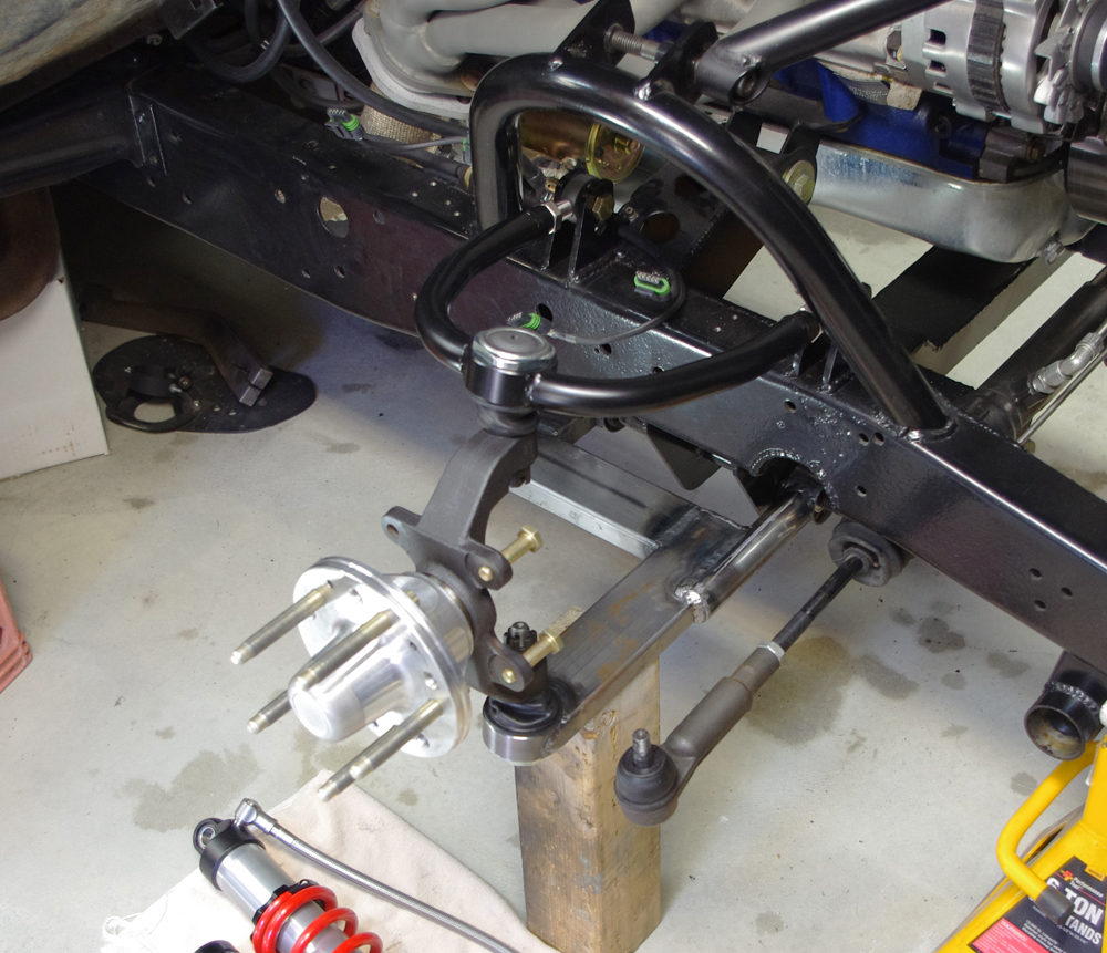
More to come... Gustave
08-24-2015 #5
Starting The Transformation
- Join Date
- Feb 2010
- Location
- El Segundo, CA
- Posts
- 268
Well, a lot of work without much visible progress.
I did get the power steering hoses finalized:
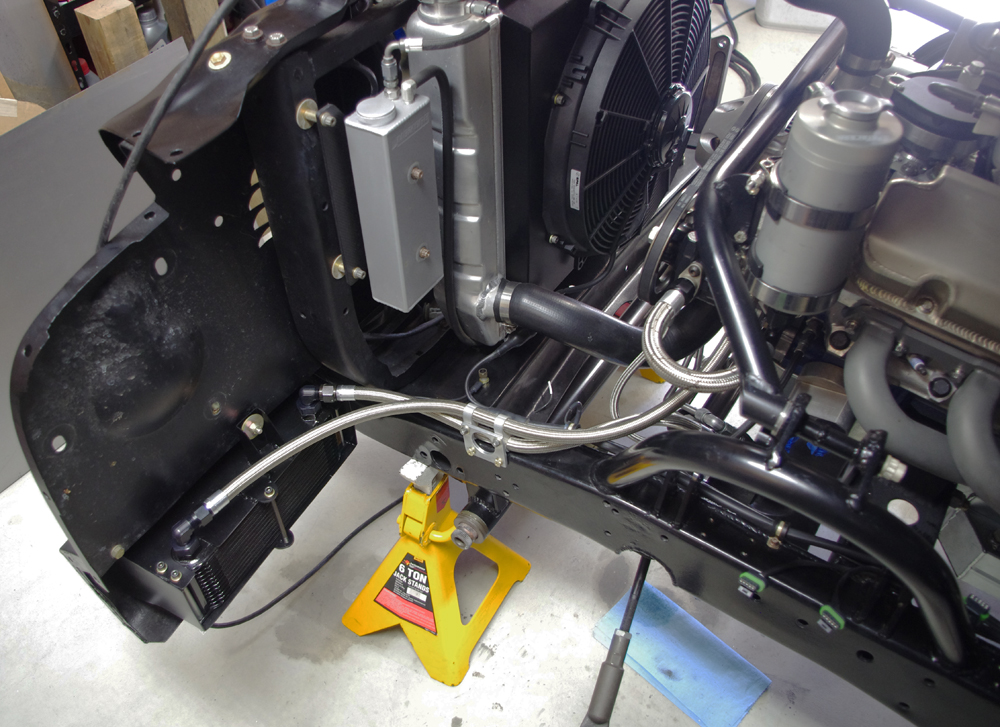
I take a lot of care when running hoses to make sure they do not (a) rub against another hose, especially a rubber hose, and that they do not (b) rub against any wiring, and (c) that they run as straight as possible to reduce pressure losses, and lastly (d) that they look somewhat visually appealing. It takes time to get the lengths and routing correct.
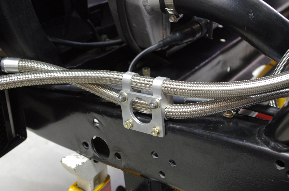
On this truck I use almost exclusively Earl's Ultra-Flex hose and connectors. This is a crimp-on style, but has a super tight bend radius (more so for the stainless than the Kevlar). It also just looks clean without the bulky reusable hose ends. I live close to Earl's Store #1 in Hawthorne so I just go down there and they make them on the spot. The guy Tom who owns the place is pretty tight with Holley (who owns Earls) so he is a good source for advice.
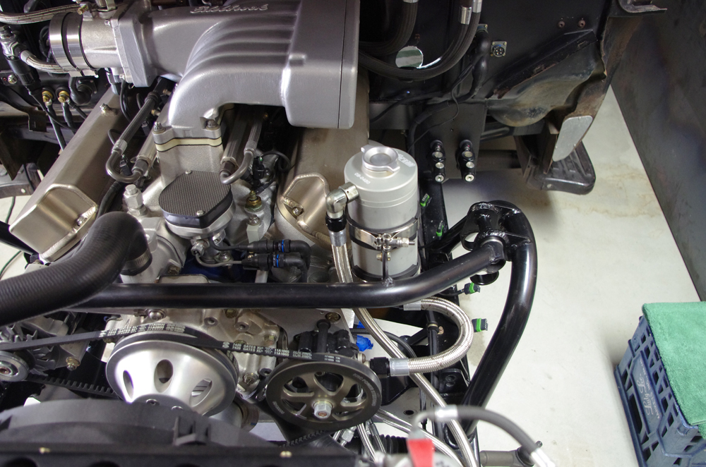
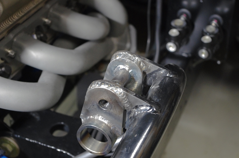
I also made some brackets to for the new upper front shock mounts. The old shocks were way too long (7" stroke) so the new ones are shorter. I also wanted the shock to mount to poly bushings to help absorb road noise and shock. We'll see how much that helps.
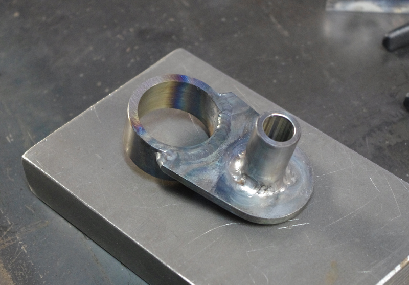
I try to TIG weld whatever I can. Once it comes to welding it to the frame I resort to MIG.
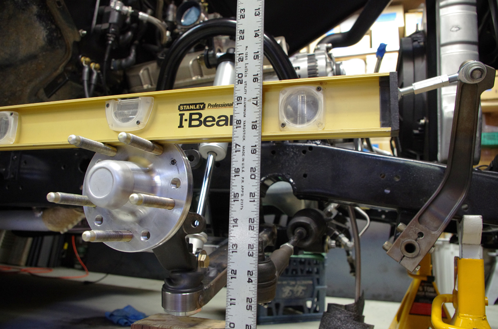
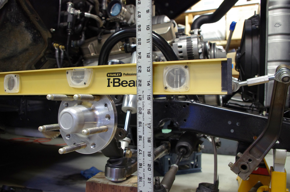
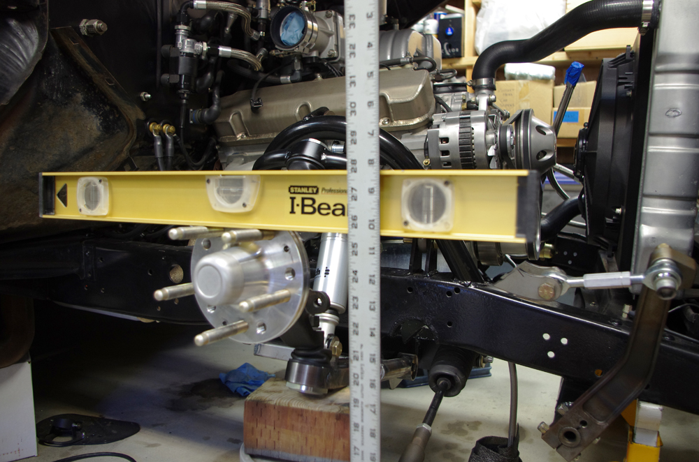
I also mocked up the front suspension to check the wheel travel from full droop to full bump (not including any bump stop which will limit bump travel a bit). The three pics show full droop, app. ride height, and full compression:
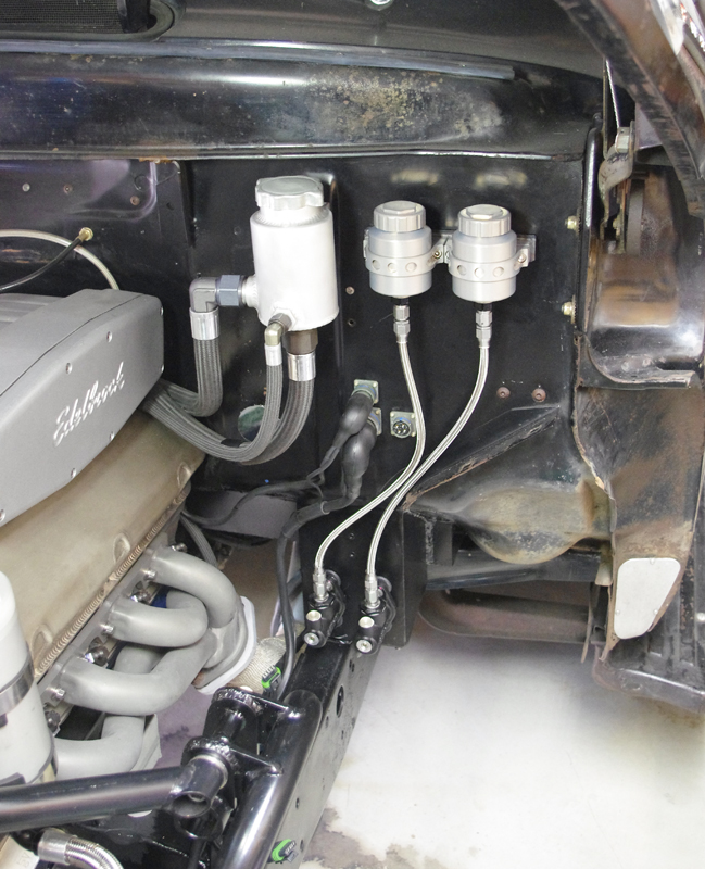
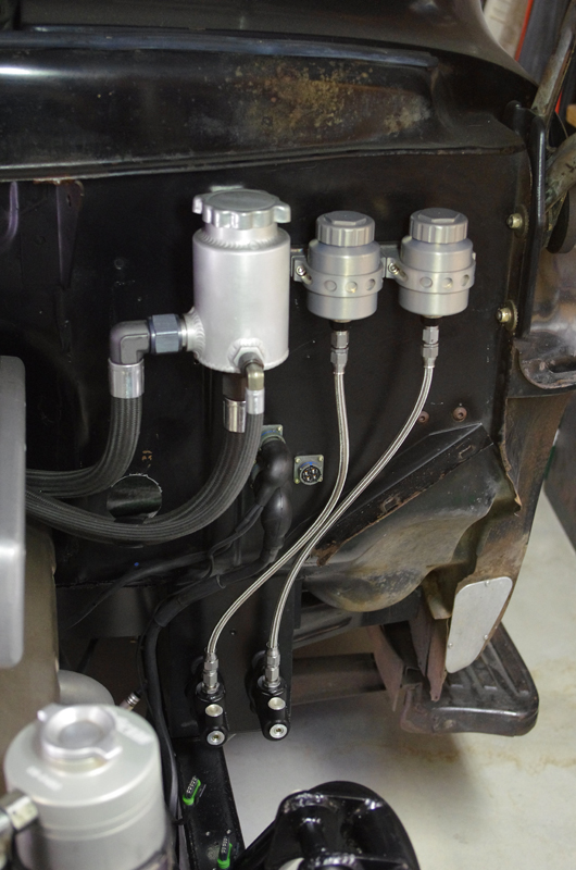
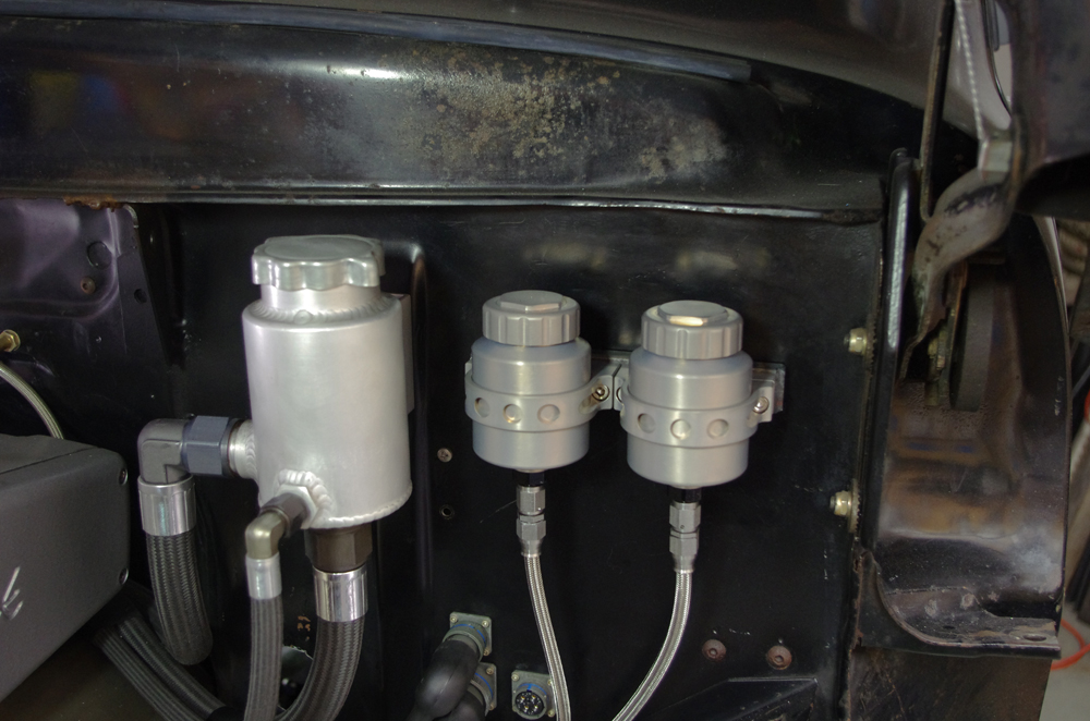
Lastly I got the new brake fluid reservoirs plumbed up. Now that the master cylinders are in the engine compartment instead of under the dash, this was necessary. I also wanted bigger volume. The previous reservoirs were mounted on the dash where the ash tray used to be. That was the only place I could find that was higher than the master cylinders in that configuration. But the reservoirs were only 1 oz each, which meant they had to be refilled frequently during bleeding. And like an idiot I had the reservoirs black anodized, which made it almost impossible to see the fluid level - resulting in a lot of brake fluid leaking down the dash onto the shifter. I did not repeat this mistake with the new Wilwood 4 oz reservoirs.
That is all for now, more to come. Gustave

 Reply With Quote