


Results 21 to 33 of 33
Thread: Triangulated 4 link question
-
02-09-2013 #21
 Registered User
- Join Date
- Oct 2012
- Posts
- 434

Got 55 degrees! I'm thinking that's all I'm getting, it's really pushing it where it is at. I did rotate the upper links, I'll have to brace them well to make sure they stay put, they aren't much above axle centerline.
-
02-10-2013 #22
Registered User
- Join Date
- Oct 2012
- Posts
- 434
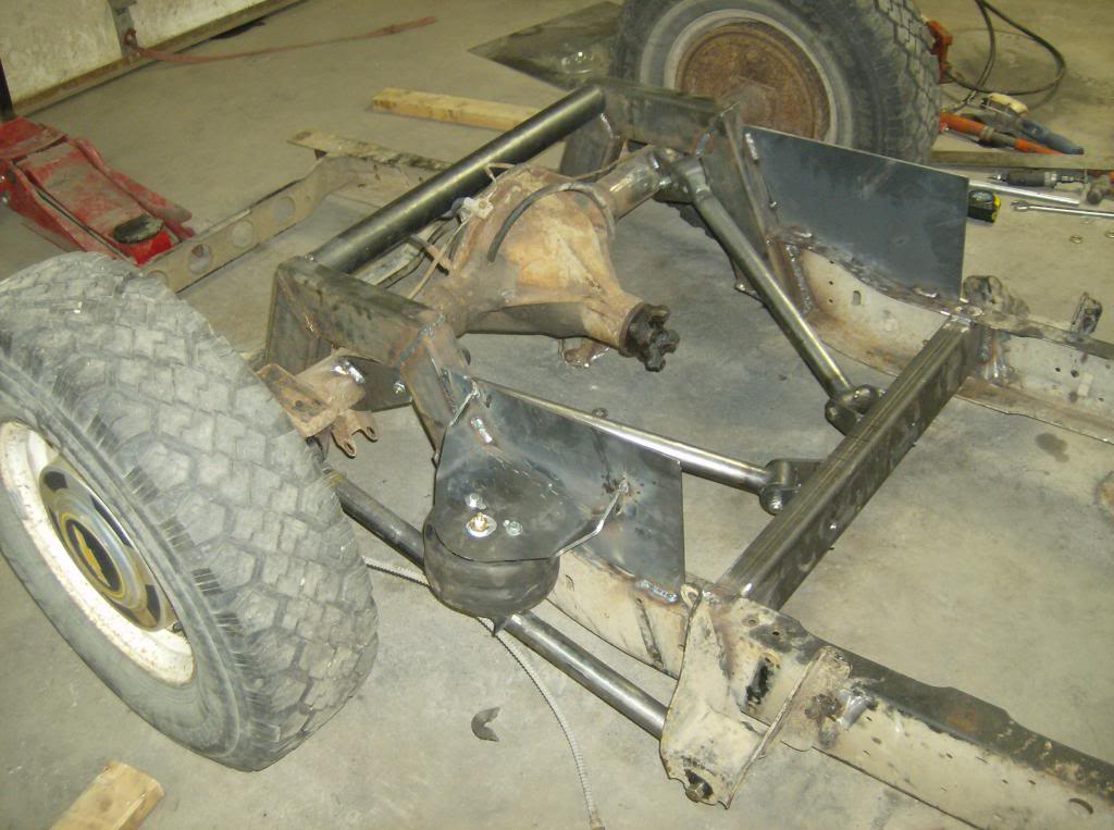
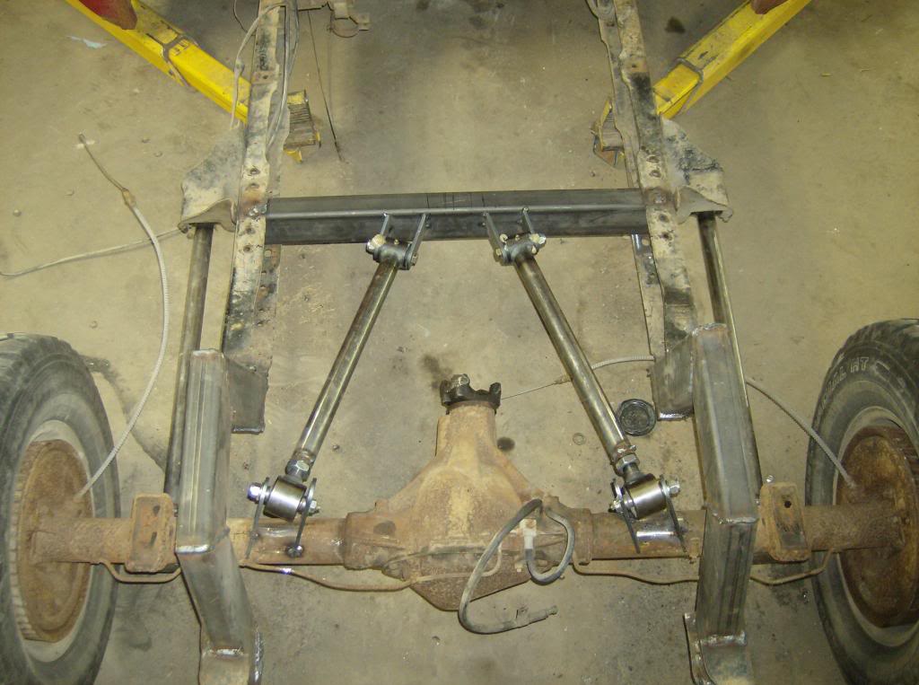
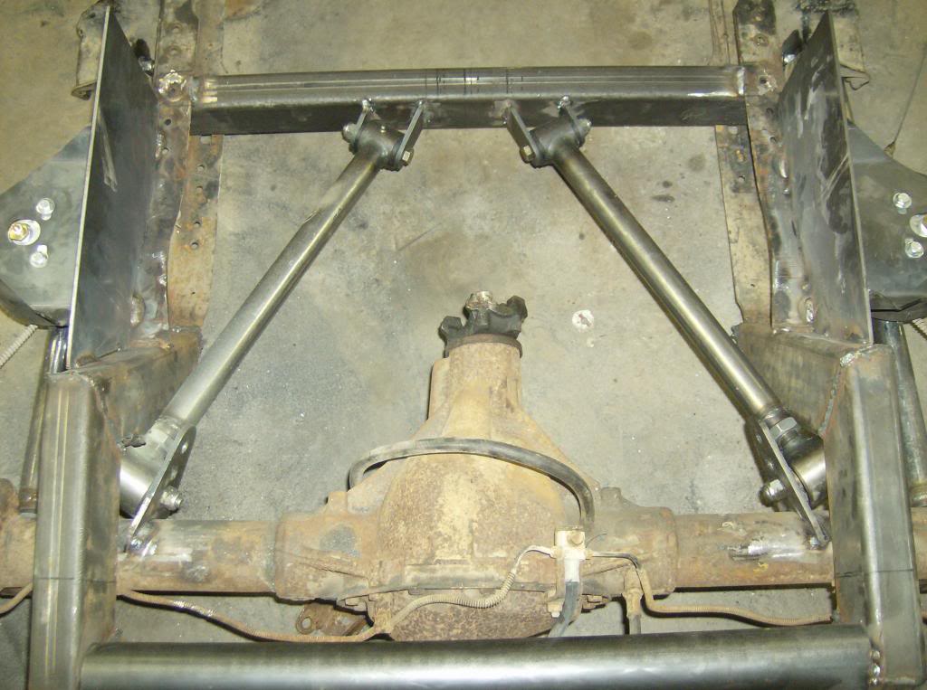
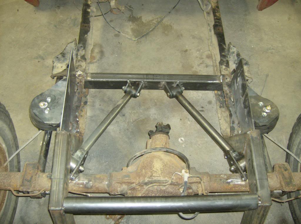
Some pictures, it's my first time so be gentle. Well, building a suspension that is! I have everything tacked in, and I do plan on trimming a few more things. I will be adding a crossmember to my plates, a driveshaft loop, and whatever else comes up. The pinion is offset on the 12 bolt, unknown to me until I triple checked my axle being centered. I have a 2 degree pinion angle at ride height, roughly 12" of travel, and no binding so far. So far I think it has turned out pretty well for my first. You can see what I am talking about with the joints ending up right in the nook of the c-notch.
02-10-2013 #23
Registered User
- Join Date
- Oct 2012
- Posts
- 434
Oops, second picture is my first set up when I didn't have the separation angle I needed. All others are final set up.
02-11-2013 #24 Registered User
- Join Date
- Nov 2002
- Location
- state of confusion
- Posts
- 1,499
Any reason why the C-notch couldn't be extended a little further forward to gain a little more clearance. Is there enough room to accommodate vertical suspension movement without contact occurring?
At 55° angle between the links, the forces in them will be almost double what they'd be at 90° included and about 10% higher than at 60°.
You might want to find out what the angle between the uppers on the Fox Mustang was (I think it was somewhat less than 90°). They converged the other way, but the force multiplication would be by the same logic = 1 / tan(half the included angle)
Norm'08 GT coupe, 5M, suspension unstockish (the occasional track toy)
'19 WRX, Turbo-H4/6M (the family sedan . . . seriously)
Gone but not forgotten dep't:
'01 Maxima 20AE 5M, '10 LGT 6M, '95 626, V6/5M; '79 Malibu, V8/4M-5M; '87 Maxima, V6/5M; '72 Pinto, I4/4M; '64 Dodge V8/3A
02-11-2013 #25
Registered User
- Join Date
- Oct 2012
- Posts
- 434
The c-notch could have been extended further ahead. There are a few reasons to why I'm where I'm at. If this was going to be more Pro-touring than a cruiser to take from show to show, I would have done an entire raised back half with a raised bed floor. Well, I would have built an entire frame, that c-channel is unreal flexible! I can't do a raised bed floor on this because I'm going to be putting my subwoofers in the box blowing through into the cab and I need the floor to box top height. Obviously this goes to show that it is not a pro-touring pickup. I'm using it as a project to learn on, I'm not trying to have it perfect by any means. It will probably never see a hard corner, but I still wanted to build it the best I could while achieving my main objective of laying frame. Definitely learned a lot. The links have tons of room before they would ever hit the c-notch. The notch was designed to lay frame on a 30.5 inch tire, and until I can buy the rims, it has the stock 28.5 inch rims. With an 8" notch, I could lay frame on a stock tire, but my future tires made it necessary to build a 10" notch. The body and frame will hit the ground before the upper rear link would hit the frame, and I would have to have no air in the bags. At ride height I believe I have 7" before any contact, whether it's frame, body, or links. I think a bag would have to explode to make that happen.
Now the forces you are talking about, would that be the axles wanting to move laterally in a turn, trying to shear the upper link brackets off the axle? If so, I'll make sure to brace it as best I can to resist that.
On a side note, do most of the aftermarket vendors (The trustworthy ones) achieve 90 degrees on their kits? I would have had to had incredibly short links!
02-11-2013 #26 Registered User
- Join Date
- Oct 2009
- Location
- New Derry, PA
- Posts
- 1,265
Mitch, what is your plan for getting the driveshaft past that crossmember? Keep in mind that there is still a lof of pulling force against the upper links, so just cutting the crossmember away until the driveshaft clears isn't the best idea...

Ray Kaufman - Wyotech Chassis Fab and High Performance Instructor. Words of Wisdom from an old master... at Asylum Custom Interiors website
02-11-2013 #27
Registered User
- Join Date
- Oct 2012
- Posts
- 434
I had planned on creating an oval loop of thick flat steel. The driveshaft moves from below to above the crossmember when it goes from lowest to highest. I had planned on cutting away the top and bottom, dropping my loop in, welding the top and bottom, cutting out the center, then finish welding the center. That way it will have contact all the way around prior to being welded.
02-11-2013 #28
Registered User
- Join Date
- Oct 2012
- Posts
- 434
I do also plan on triangulating the crossmember with braces running just off center to the frame ahead of the crossmember.
02-11-2013 #29
Registered User
- Join Date
- Oct 2009
- Location
- New Derry, PA
- Posts
- 1,265
Good idea. Originally Posted by mitch_04

Ray Kaufman - Wyotech Chassis Fab and High Performance Instructor. Words of Wisdom from an old master... at Asylum Custom Interiors website
02-11-2013 #30
Registered User
- Join Date
- Oct 2012
- Posts
- 434
Just wanted to say thanks again, you guys are a huge help. Absolutely love this site, after spending hours in the project updates I've went from thinking a C-5 suspension in a vehicle would have been impossible to wondering what I should try to put one in.
03-10-2013 #31
Registered User
- Join Date
- Oct 2012
- Posts
- 434
Enough bracing?
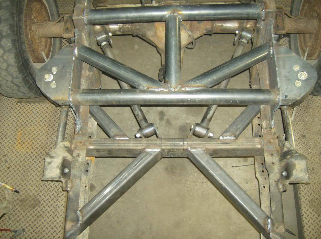
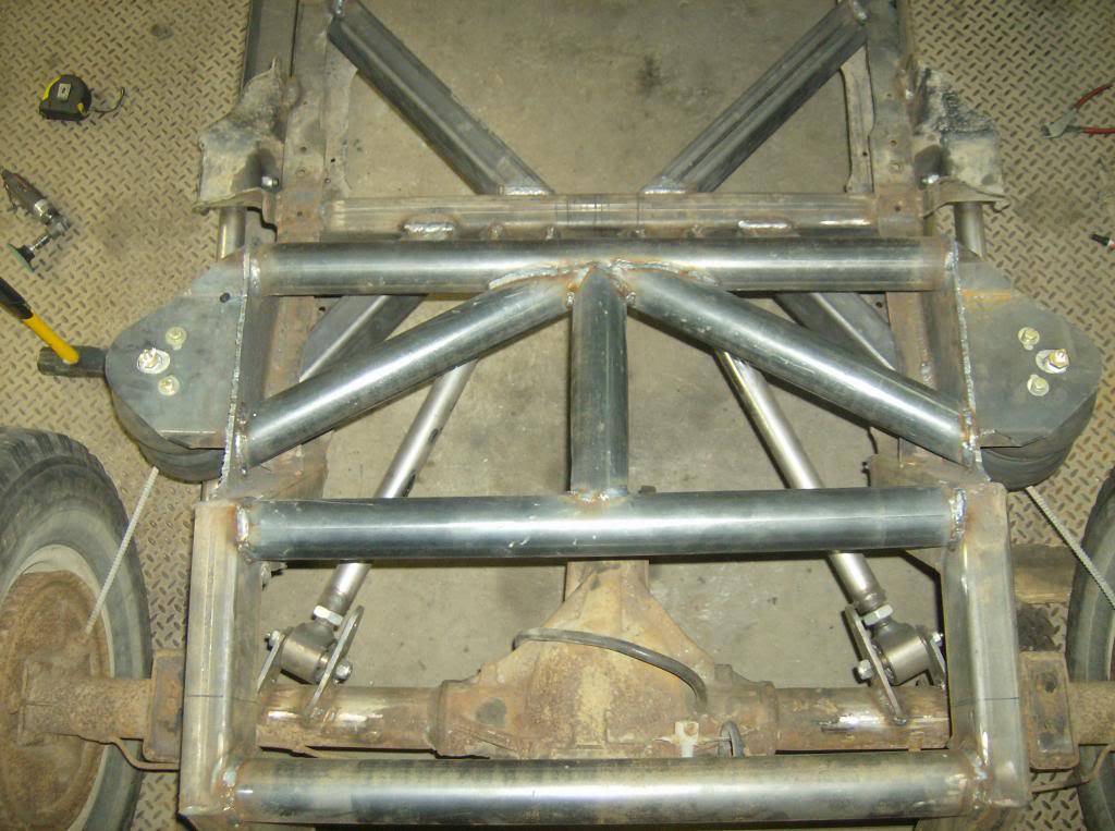
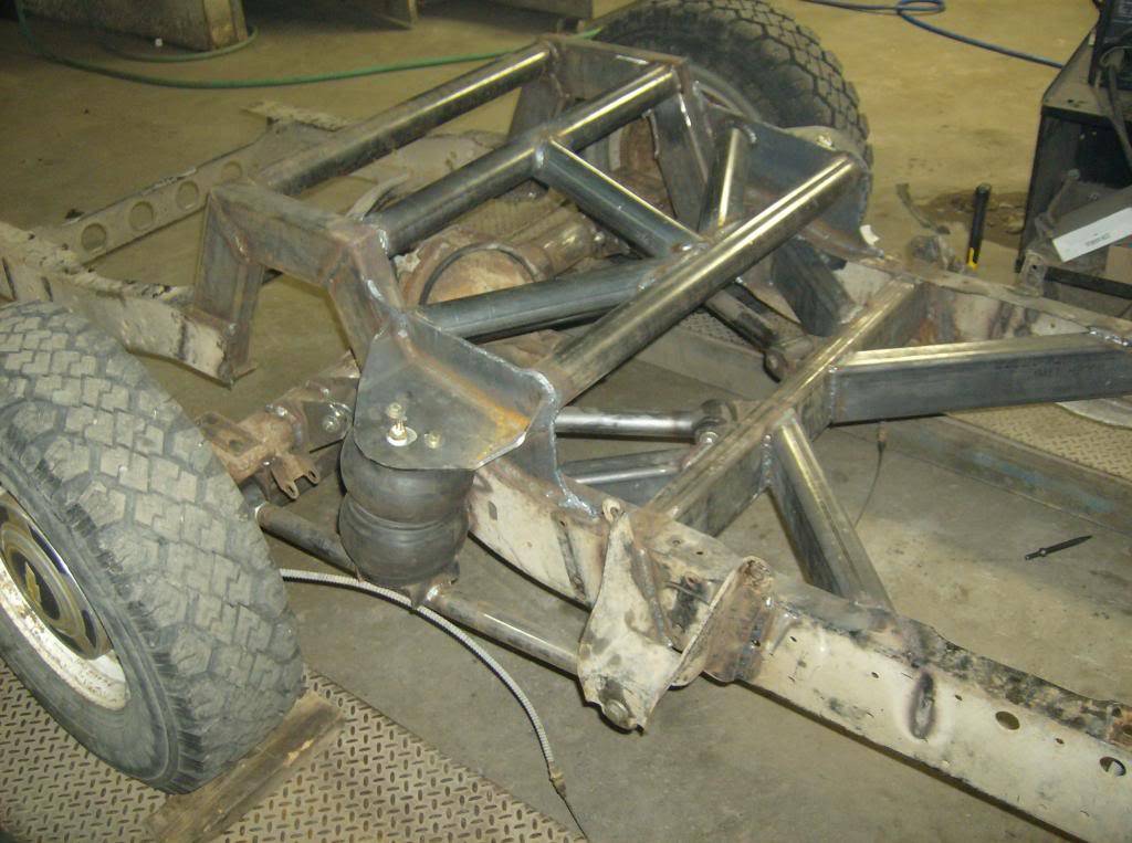
I may put a couple more round tubes to triangulate the rear c-notch bar to the front. I was having a blast doing all of this, I may have overdone it a little! Oh well, overkill is underrated. It's just so much fun, I've been wanting to do a huge build like this since I was probably 11 or 12. I finally am doing one that's up to my standards, which seem to far outweigh any of my "car buddies". Most of them just get a vehicle running, through a 15 ft paint job on it, and call it good. I've been reading Hot Rod magazine and the like for way too many years to keep it that simple....although I could have built about 3 cars in the same time!
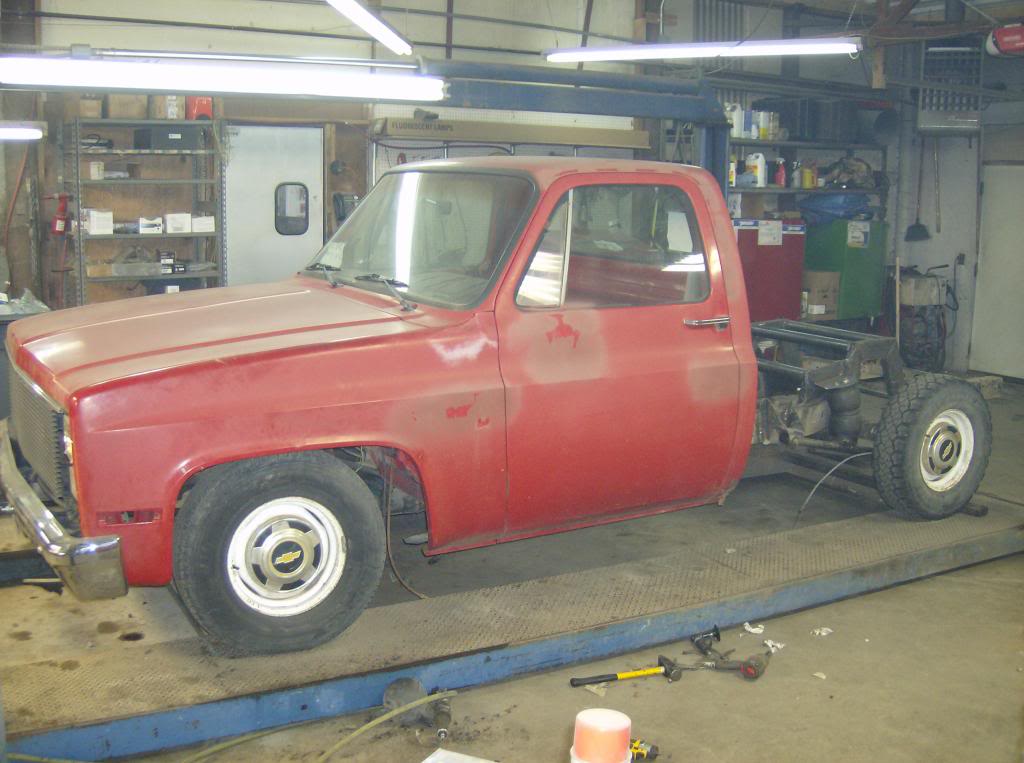
Might as well throw one in of the vehicle as it sits. I have officially hit my main goal, rockers are touching.
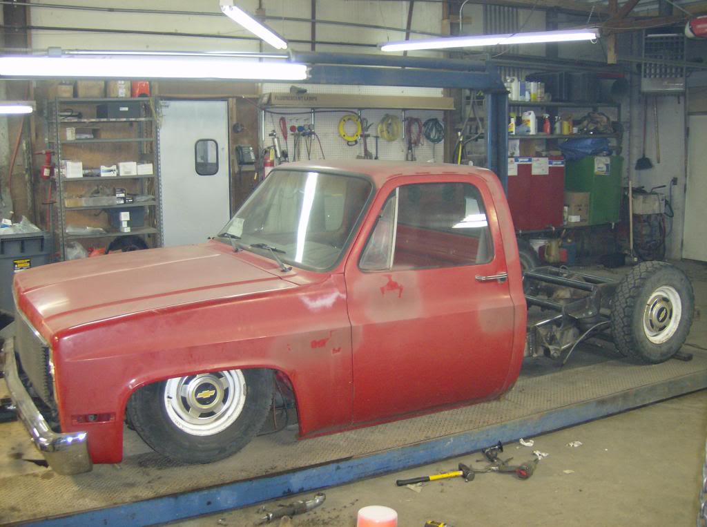
11-14-2013 #32
Registered User
- Join Date
- Dec 2011
- Location
- Arizona
- Posts
- 21
Cool build. I'm in the process of building my rear suspension and fabbed up some brackets similar to yours ( the ones attaching the control arms to the axle and crossmember). I found it was a pita to align them and I didn't think they would be sturdy enough. So I made these. Just thought I'd give u an idea. I can post more pics if u need. The other end is radiused to the diameter of the axle tube and at the appropriate angle.
Adrian R.
It's not the mountain in front of you that slows you down, it's the pebble in your shoe. - unknown author
11-14-2013 #33
Registered User
- Join Date
- Oct 2012
- Posts
- 434
I have since welded on a "cap" to my link brackets tying them together and triangulating them to the crossmember, but thanks for the idea. Next time I build a suspension I will build my own link brackets vs using the ones that come with the kit. It was easier for me to learn by getting the kit, but now that I know what I want I'll do it a little differently.

 Reply With Quote


