

Results 1 to 20 of 30
-
10-04-2012 #1

 Registered User
- Join Date
- Aug 2004
- Location
- Manteca, CA
- Posts
- 383
Ridetech triangulated 4 link modification
Ok.... Perfect example of change one thing to make the car cool and open pandoras box
Started with the ridetech air bar system for my 70 barracuda...... Not low enough when it's all aired out... So my builder cut down the upper shock mount about 2 inches.. Now it looks badass all aired out.... Sweet
Downside..... using the stock Ridtech stuff the LCA is now angled up front to back at ride height since the rear end is now up 2 inches..... And so is the UCA ( I don't think it was dead horizontal with the stock set up either but not sure).... I don't think the UCA/LCA are dead parallel in the stock configuration, but not sure...
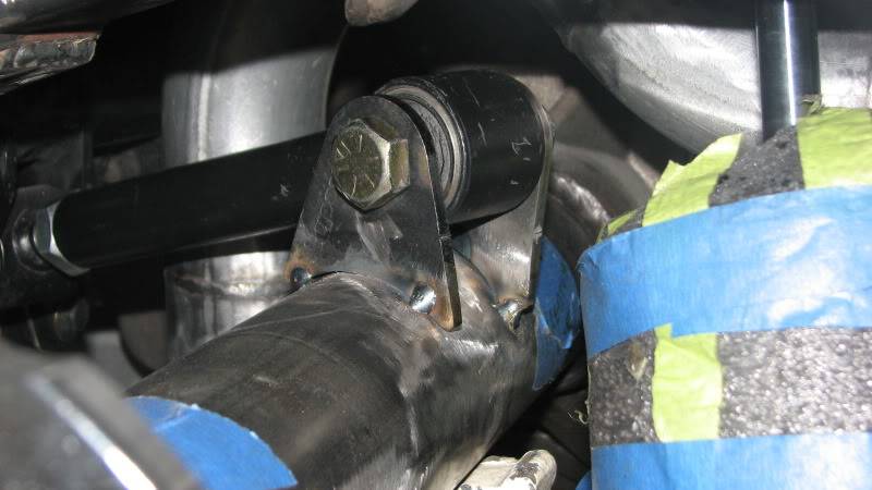
Hate the look and bulk of the u-bolt design of the brackets on the rear end so I find a guy to make one piece brackets with the same layout as the ones in the kit.... But figure I can add some bolt holes that will drop the LCA to horizontal at ride height.... And add some adjustability to fine tune stuff if needed....
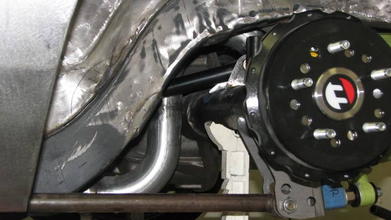
Get it all mocked up... Set my pinion angle ... All tacked together.. Nothing finalized
Now my concerns
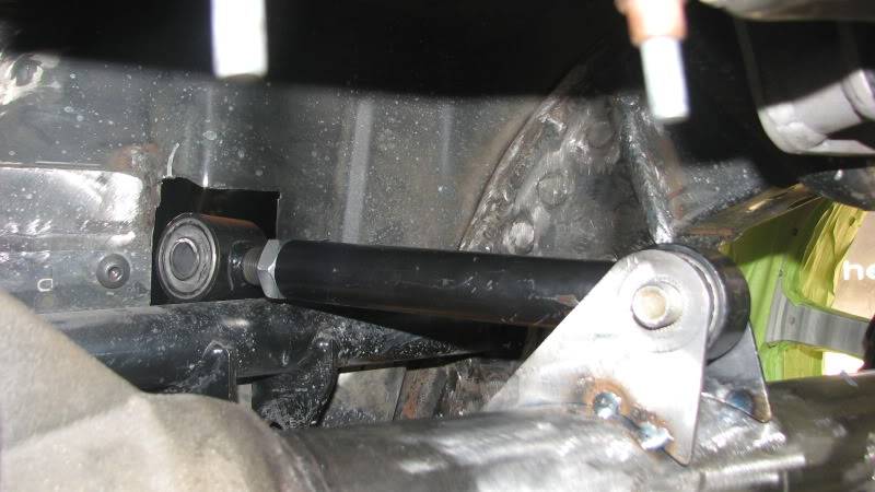
(1) The UCA and LCA aren't parallel to each other.... The UCA is angled up about 18 degrees.... The LCA is dead horizontal if I use the lowest hole on the bracket on the rearend
(2) The LCA is 21 inches.... The UCA is at about 9.5 inches (it's adjustable)....I guess ideal is UCA is about 70% length of LCA.... No way for this to happen even in the stock configuration so I think that's a compromise from the start. If I do some HS algebra, with the rearend back down 2 inches (where it would have been if I didnt start messing with stuff), the UCA would have been about 9.25 inches long....still pretty short....
(3) When I raise or lower the car, the pinion angle seems to change several degrees with only a small change in car height ..... When its all aired out we are talking about 7 degrees different from ride height pinion angle.... I think this is a function of UCA vs LCA length and maybe not having them parallel.....
So.... Can't really make the UCA much longer...maybe 1/2-3/4 inches at best if I make taller brackets that I can position cloer to the back side of the rearend tube (not dead over the centerline of the tube) ....I can adjust the LCA back up to make it closer to parallel with the UCA.... But then it's angling up front to back, which is not ideal
Cant move the UCA front mount without some major fabrication....
Car won't be a hard core track car so perfect suspension geometry isn't my goal.... But I want the car to be responsive and predictable on the street.... No hideous vibrations or unpredictable handling..... So not shooting for perfect......
So do I shoot for making the bars parallel but angled up..... Or LCA horizontal and UCA stay angled up and make the UCA as long as possible?
The drastic and rapid change in the pinion angle is the thing that has me worried.....
Im hoping maybe some ridetech guys will chime in too........now that I've screwed with the original Ridetech set-up
Ned
Manteca, CA
My '69 Camaro
My Camaro Movie
My '70 Cuda Project Thread
My Cuda Project Pix
Cuda Project Sponsors/Builders
Bruning Auto Design,
Bowler Transmission, Air Ride Technologies, American Autowire, Vintage Air, Comp Cams/F.A.S.T
Carter Hickman Designs
-
10-04-2012 #2 Registered User
- Join Date
- Nov 2008
- Location
- Lawrenceburg, TN
- Posts
- 4,098

10-04-2012 #3
Registered User
- Join Date
- Aug 2004
- Location
- Manteca, CA
- Posts
- 383

 Ned
Ned
Manteca, CA
My '69 Camaro
My Camaro Movie
My '70 Cuda Project Thread
My Cuda Project Pix
Cuda Project Sponsors/Builders
Bruning Auto Design,
Bowler Transmission, Air Ride Technologies, American Autowire, Vintage Air, Comp Cams/F.A.S.T
Carter Hickman Designs
10-04-2012 #4
Registered User
- Join Date
- Aug 2004
- Location
- Manteca, CA
- Posts
- 383
Those are sitting at ride height.... when I had the new LCA brackets made, I didnt have them cut the LCA holes where the LCA would have mounted in the original set-up with everything just raised up 2 inches (figured I would never use it)...but I can easily add that hole. It would be about 2 inches up from that lower hole.....so even with that, I dont think the UCA and LCA would have been dead parallel with each other....but closer
Ned
Manteca, CA
My '69 Camaro
My Camaro Movie
My '70 Cuda Project Thread
My Cuda Project Pix
Cuda Project Sponsors/Builders
Bruning Auto Design,
Bowler Transmission, Air Ride Technologies, American Autowire, Vintage Air, Comp Cams/F.A.S.T
Carter Hickman Designs
10-04-2012 #5 Registered User
- Join Date
- Oct 2009
- Location
- New Derry, PA
- Posts
- 1,265
You are pretty much spot on with your assessment of the problems. The system just wasn't designed to run at that low ride height. The fix for pinion angle is to get the links more parallel at your lower ride height, but that's going to mean some major fab on the floor pan. Raising the rear LCA mount back up will help, but that's the problem you were addressing to start with, wasn't it? Originally Posted by DRJDVM's '69


Ray Kaufman - Wyotech Chassis Fab and High Performance Instructor. Words of Wisdom from an old master... at Asylum Custom Interiors website
10-05-2012 #6
Registered User
- Join Date
- Aug 2004
- Location
- Manteca, CA
- Posts
- 383
My thoughts at this point is to make tabs that sit on top of that crossbar for the front UCA mount.... Instead of the stock location under it
That may be possible without a ton of work.... Just a PITA
If I do that the bars may be a bit shorter and slightly angled down from front to backNed
Manteca, CA
My '69 Camaro
My Camaro Movie
My '70 Cuda Project Thread
My Cuda Project Pix
Cuda Project Sponsors/Builders
Bruning Auto Design,
Bowler Transmission, Air Ride Technologies, American Autowire, Vintage Air, Comp Cams/F.A.S.T
Carter Hickman Designs
10-06-2012 #7
Registered User
- Join Date
- Oct 2009
- Location
- New Derry, PA
- Posts
- 1,265
You will still have some pinion change from the different length arms, but raising the front UCA pivots will definitely help. If they end up going uphill to the frame as you think, can you make slightly longer tabs for the axle to level things out again? It sounds like fine tuning the I/C isn't your top priority, so starting out with the links parallel in side view will at least keep the pinion moving the same direction through the full range of motion.
Ray Kaufman - Wyotech Chassis Fab and High Performance Instructor. Words of Wisdom from an old master... at Asylum Custom Interiors website
10-06-2012 #8
Registered User
- Join Date
- Aug 2004
- Location
- Manteca, CA
- Posts
- 383
My thoughts exactly.... I was thinking of making taller tabs on the axle to get things parallel
The arms will never be perfect complimentary lengths.... Even in the stock ridetech set up they were no way matched.... There just isn't room without huge modification
And yes, my goal is not perfect geometry.... It's going to see an occasional track day or autoX but will be 99% street car.... Just want it easy to drive and predictable without some horrible annoying driving characteristicNed
Manteca, CA
My '69 Camaro
My Camaro Movie
My '70 Cuda Project Thread
My Cuda Project Pix
Cuda Project Sponsors/Builders
Bruning Auto Design,
Bowler Transmission, Air Ride Technologies, American Autowire, Vintage Air, Comp Cams/F.A.S.T
Carter Hickman Designs
10-06-2012 #9 Registered User
- Join Date
- Aug 2009
- Location
- Napa, Ca.
- Posts
- 190
Ned I am getting ready to tackle the same thing on my 69 Camaro. Ride height isn't as low as I want it so we contemplated using the DSE shock crossmember... The piece you weld in between the tubs that is cut into the trunk so the upper shock mounts are raised.
I ran into Brett at the Pleasanton GG show and asked him about it to get his thoughts. I have the airbar and one of Prodigy's Moser 12 bolts which I know I will have to change the mounts on since the pinion angle is off so I will be able to play with the mount locations. Anyway, he had concerns that raising the upper shock mount by modifying the shock crossbar it would throw off the geometry too much. He recommended I call and talk to Rodney. Brett said he has worked with a few other customers who have tried things like this and may have some ideas. I haven't called yet but he may be worth reaching out to for you.
Good luck and I will be watching as you work through it. Please keep us updated... Will do the same.Jeff
69 Camaro build, body & paint by West Coast Auto Craft
Build thread http://www.lateral-g.net/forums/show...ght=brownstone
Lateral-g Feature http://www.lateral-g.net/forums/showthread.php4?t=44186
Thanks to Matt's Classic Bowties and Pro-Touring.com
10-07-2012 #10
Starting The Transformation
- Join Date
- May 2008
- Location
- Toronto
- Posts
- 213

I would be inclined to put the LCA back where it was originally to restore the geometry. Then I would move both the LCA and UCA mounting points on the car up equal amounts to correct the ride height and CA angles.
This would maintain the geometry of the original kit.
Without running it through a suspension program or plotting it out yourself on a large piece of drafting paper it's really hard to know the affects of the changes.
I'm not sure that addressing the angle of the lower without the upper has helped you at all, now the relationship between the two are different.
You may be better off with both pointing down.
Call the manufacturer and see what they say.
Keith.
10-07-2012 #11 - Sponsor & Rat Pack Member -
- Join Date
- Oct 2004
- Location
- Indiana
- Posts
- 1,371
For your design parameters, you may be using the wrong product. The ridetech 4link was designed to get the car as low as feasible, as defined by the limits of the driveshaft tunnel and the floorpan. Can the car be built lower? Absolutely, but it will be exponentially more work. One consideration is what suspension will be on the front? Getting the rear of the car low is fine, but will look weird if it is lower than the front.
If you are going to modify the ridetech 4 link, I would start out with the universal weld on 4 link instead. You'll save money and it will be easier to modify. It's available in either triangulated or a parallel version. Then you can pick your intended ride height and build from there.
Another solution is to use the ShockWaves. Then you can set the car down to look better when parked and pick it up to drive or race it. Don't let anyone convince you that air suspension will not perform as well as coil overs. It will. I've proven it over and over and over.
As you've already seen, your current modifications are problematic and will result in an unhappy car and driver. The pinion angle migration is severe, the instant center is too far back and will create tire spin on acceleration and wheel hop on braking. You'll end up with a car that looks mean but isn't. No easy fix. If you absolutely positively have to get the car lower, it will take time and money.Bret Voelkel
Director of Innovation Fox Powered Vehicles Group
Founder/ Former Owner
RideTech/Air Ride Technologies, Inc.
How do you spell Impossible?
10-07-2012 #12
- Sponsor & Rat Pack Member -
- Join Date
- Oct 2004
- Location
- Indiana
- Posts
- 1,371
I just reread your original post...you are already using ShockWaves. Just how much lower are you trying to get?
To address one of your specific questions, the uca angle should be nose down by 2-3 degrees at ride height. That will minimize the pinion angle migration and give you an instant center that will give you some bite and avoid brake hop. About the only way to accomplish that on your car is to get up into the floorpan. Don't forget to check driveshaft clearance...you'll likely have to take out most of the tunnel as well to get that low.Bret Voelkel
Director of Innovation Fox Powered Vehicles Group
Founder/ Former Owner
RideTech/Air Ride Technologies, Inc.
How do you spell Impossible?
10-07-2012 #13
Starting The Transformation
- Join Date
- May 2008
- Location
- Toronto
- Posts
- 213
That's what I love about this forum, you didn't even have to call the manufacturer, he's right here.
10-07-2012 #14
Registered User
- Join Date
- Aug 2004
- Location
- Manteca, CA
- Posts
- 383
Hey Bret...thanks for chiming in.
The front suspension/frame is all channeled etc, so the car has been dropped in front and back to get the overall stance I'm looking for....so it wont be "ass down and nose up". No where near the stock set-up in front either.
The trans tunnel is all cut out....when this whole deal started I knew I was going to have to cut tunnel and floor etc, so I'm not trying to do this in the confines of the stock tunnel etc.
I am using the shockwaves.....the Airbar is all welded in, so it would be near impossible to pull out and start all over... I'm going to have to use the bar as a starting point and work from there
Moving the front mount of the LCA is out of the question.....way too much would need to change.
My goal is to get the geometry between the UCA and LCA better. I think my best bet is to make new mounts for the UCA...use the Airbar as my base, make new tabs to weld to that and maybe new tabs on the axle.
So I guess my last question is what angles am I shooting for at ride height?.... LCA dead horizontal to 1-2 degrees down (front to back).....and the UCA dead level to 1-2 degrees up (front to back) ????Ned
Manteca, CA
My '69 Camaro
My Camaro Movie
My '70 Cuda Project Thread
My Cuda Project Pix
Cuda Project Sponsors/Builders
Bruning Auto Design,
Bowler Transmission, Air Ride Technologies, American Autowire, Vintage Air, Comp Cams/F.A.S.T
Carter Hickman Designs
10-07-2012 #15
Registered User
- Join Date
- Aug 2004
- Location
- Manteca, CA
- Posts
- 383
Bret....if there is someone specific at ridetech I should contact to discuss more details, please let me know who....
Ned
Manteca, CA
My '69 Camaro
My Camaro Movie
My '70 Cuda Project Thread
My Cuda Project Pix
Cuda Project Sponsors/Builders
Bruning Auto Design,
Bowler Transmission, Air Ride Technologies, American Autowire, Vintage Air, Comp Cams/F.A.S.T
Carter Hickman Designs
10-07-2012 #16
- Sponsor & Rat Pack Member -
- Join Date
- Oct 2004
- Location
- Indiana
- Posts
- 1,371
I'm in Texas right now but Darren or Rodney are the most familiar with the engineering side of it. We also have a multi hole weld on lower arm bracket that might help get the lower bar approx level at ride height. On the upper bar shoot for 2-3 degree nose down at ride height. More than 5 is getting problematic. Never let the upper bar run downhill to the reared.
Bret Voelkel
Director of Innovation Fox Powered Vehicles Group
Founder/ Former Owner
RideTech/Air Ride Technologies, Inc.
How do you spell Impossible?
10-08-2012 #17
Registered User
- Join Date
- Aug 2004
- Location
- Manteca, CA
- Posts
- 383
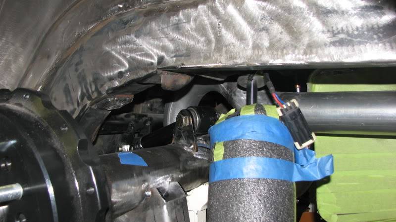
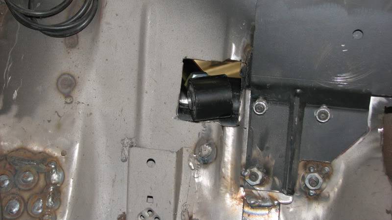
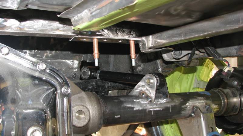
Looks like my only option to get the suspension geometry anywhere near idea is to make brackets on the top side of the front UCA bracket...so out came the cut off wheel....
With everything just laying in there, the UCA slope down a couple of degrees.....but I'm pretty sure I can just make the axle bracket taller and get it near level to angle a couple of degrees up (front to back). Its doable....just more work.....picked up some 3/16 plate today...time to fab some brackets. I'll just make a "pocket" in the floor to cover up the brackets.
 Ned
Ned
Manteca, CA
My '69 Camaro
My Camaro Movie
My '70 Cuda Project Thread
My Cuda Project Pix
Cuda Project Sponsors/Builders
Bruning Auto Design,
Bowler Transmission, Air Ride Technologies, American Autowire, Vintage Air, Comp Cams/F.A.S.T
Carter Hickman Designs
10-08-2012 #18 Registered User
- Join Date
- Mar 2005
- Location
- St George Utah
- Posts
- 1,243
There is a good chance that having the UCA up that high is goting to KILL any anti squat that may have been built into the system. Ihe I/C may end up on the moon! when it sould be some whare arroung the shifter ball( as a giudeline) maybe a little back and down from there.
check out performance trends 4 link software. it can plot all the locations and tell you where the I/C will be and what the anti squat % will be. I like to keep the AS at about 120-130% or so. any number over 100% means the rear housing will want to Seperate from the chassis planting the tires. anything less and the housing will compress towards the chassis.
I am sure Ray will correct me if I am off a bit lol
10-08-2012 #19
Registered User
- Join Date
- Aug 2004
- Location
- Manteca, CA
- Posts
- 383
Blake...correct me if I'm wrong here...my plan is to move the mount on the axle up also....so that the UCA is horizontal to a couple of degress down in the front....that should keep the I/C in a reasonable location...so the anti-squat shouldnt be way off.... I'm not leaving the UCA angled down like the pix....
Basically what I'm trying to do...since the shock mount got moved up about 2 inches....I'm moving the LCA axle mount down 2 inches to keep it horizontal....and the front UCA mount up 2 inches and the axle UCA mount up 2 inches...essentially just moving the UCA and LCA farther apart vertically.... that should keep all the goemetry the same as "stock"....Ned
Manteca, CA
My '69 Camaro
My Camaro Movie
My '70 Cuda Project Thread
My Cuda Project Pix
Cuda Project Sponsors/Builders
Bruning Auto Design,
Bowler Transmission, Air Ride Technologies, American Autowire, Vintage Air, Comp Cams/F.A.S.T
Carter Hickman Designs
10-08-2012 #20
Registered User
- Join Date
- Aug 2004
- Location
- Manteca, CA
- Posts
- 383
The more I read on all this stuff, the more confused I become..... I played with the demo of the Performance Trend 4 link stuff..... based on the Camaro Demo, my AS would be WAY better if I had the UCA angled dramatically up from front to back...which is what is killing me when it comes to the pinion angle change...
If I have the LCA horizontal,,,,and the UCA angled slightly up (front to back), the best AS I could get was 25%.....
So with a parallel 4 link like alot of guys run, is the AS zero?....since the UCA and LCA lines never meet..
No idea what the AS is in the stock AirBar configuration
Once again....not building a race car...just want it to be reasonable to drive......and predictableNed
Manteca, CA
My '69 Camaro
My Camaro Movie
My '70 Cuda Project Thread
My Cuda Project Pix
Cuda Project Sponsors/Builders
Bruning Auto Design,
Bowler Transmission, Air Ride Technologies, American Autowire, Vintage Air, Comp Cams/F.A.S.T
Carter Hickman Designs

 Reply With Quote


