

Results 1 to 17 of 17
Thread: PCV Question
-
04-11-2012 #1

 Registered User
- Join Date
- Jan 2006
- Posts
- 1,747

PCV Question
My valve covers have a grommet for a PCV valve and I can't find any LS based engine that actually used one so I think it must be for a fitting not a PCV valve. Anyone have any input on proper PCV plumbing using a catch can (Like Norris Motorsports)? I'm getting close to having mine ready to run and want to be sure I have everything installed in advance of first start up to prevent any problems (not that no PCV will cause problems initial startup problems but want it done).
Thanks!
GeoffP
68 Camaro - LS1/T-56
-
04-11-2012 #2
Registered User
- Join Date
- Sep 2010
- Location
- Santa Clara, CA
- Posts
- 622
Geoff, I was going to refer you to this GREAT thread about PCV and catch cans until I realized that it is YOUR thread. What wasn't answered there?
Steve
04-11-2012 #3
Registered User
- Join Date
- Jan 2006
- Posts
- 1,747
I got my answer on the catch can but not on the actual PCV valve. What I don't know is if LS engines need a regulated flow rate provided by a PCV valve like a small block chevy would. I am still looking at catch cans too trying to figure out what to buy. My funds are so limited that I have to watch what I spend and can't afford to buy only to find out something doesn't work and buy again.
Thanks!GeoffP
68 Camaro - LS1/T-56
04-11-2012 #4
Registered User
- Join Date
- Jan 2006
- Posts
- 1,747
I don't find anything about LS PCV systems having any kind of restrictor/valve in them - it might be that I just need to get one of Norris' catch cans and be done with it. I'll have to save my pennies for that though.
GeoffP
68 Camaro - LS1/T-56
04-11-2012 #5
 Registered User
- Join Date
- Nov 2006
- Location
- Mountain Springs, Texas
- Posts
- 4,825
Thunder Racing has an LS6 PCV conversion kit. Not inexpensive though:
http://www.thunderracing.com/shop-by...n-Kit_613.html1969 Camaro - LSA 6L90E AME sub/IRS
1957 Buick Estate Wagon
1959 El Camino - Ironworks frame
1956 Cameo - full C5 suspension/drivetrain
1959 Apache Fleetside
04-11-2012 #6
Registered User
- Join Date
- Jan 2006
- Posts
- 1,747
After mulling over it some I think that any oil/air separator that is properly designed should do just fine. I found one a little lower cost on eBay that looks to have a similar design and is well liked on other boards and is made in the US so I'm probably going to pull the trigger on it. If it doesn't work like I expect I'll just save up my $$$ for one of Mr. Norris' cans.
GeoffP
68 Camaro - LS1/T-56
04-11-2012 #7 Registered User
- Join Date
- Nov 2008
- Location
- Lawrenceburg, TN
- Posts
- 4,098
from what I have noticed is that early LS motors had a baffled breather port on the rear of the left(drivers) valve cover, later models were changed to a replaceable and regulated PCV to reduce the deceleration blow by that was loading oil into the intakes, there was no definite switch date,, it started on the LS2 (from what I've seen) before it rolled to the other series engines (IE 1,3,6 so on)
04-11-2012 #8
Registered User
- Join Date
- Sep 2010
- Location
- Santa Clara, CA
- Posts
- 622
Geoff: I don't know if this will answer your questions and I'm not certain that it is the same for all LS engines, but this is from the GMPP documentation for my LSX 454 (I added the highlight):
Positive Crankcase Ventilation System (PCV)
How the PVC system works:
A closed crankcase ventilation system should be used in order to provide a more complete scavenging of crankcase vapors. Filtered air
from the air induction system (air cleaner) duct is supplied to the crankcase, mixed with blow-by vapors, and passes through a crankcase
ventilation metering device before entering the intake manifold. The primary component in the positive crankcase ventilation (PCV) system
is the PCV flow metering orifice. Vacuum changes within the intake manifold result in flow variations of the blow-by vapors. If abnormal
operating conditions occur, the design of the PCV system permits excessive amounts of blow-by vapors to back flow through the crankcase
vent tube and into the engine induction system (air cleaner) to be consumed during normal combustion. This engine ventilation system
design minimizes oil consumption and significantly reduces the potential for oil ingestion during vehicle limit handling maneuvers.
How to set up your PVC system:
There are three ports on the LSX long block that make up the PCV system. There are two foul side ports. Both of these ports should be
connected to the intake manifold and be exposed to vacuum at idle.
The two ports are 1) Front port on the valley cover. 2) Left rear (driver) valve cover. These two silver tubes may look simple but, they should
not be modified. Both of the tubes have a small orifice within them that, is used in place of a PCV valve of early designs.
There is one fresh air port which is on the front of the right (passenger) valve cover. Again this is a silver tube that faces forward on the valve
cover. This port should be connected to filtered clean air. This is typically within the engines air cleaner system or can be a separate air
filter if using a carburetor. If you are planning on an electronic fuel injections system that uses a mass air flow meter (MAF) then, the fresh
air to the PCV should be installed between the MAF and engines throttle body. The engine burns the air that enters the PCV system so,
if the fresh air port is prior to the MAF then, this air will enter the engine without being measured by the MAF.Steve
04-19-2012 #9
Registered User
- Join Date
- Jan 2006
- Posts
- 1,747
Yes this is exactly what I wanted to know! Thank you!!
GeoffP
68 Camaro - LS1/T-56
04-22-2012 #10
Registered User
- Join Date
- Jan 2006
- Posts
- 1,747
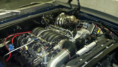
I did my PCV setup yesterday. I put an On3Performance oil catch can in line to the intake to help with any oil issues. It's a nice piece though they put bigger fittings on it than needed. I was able to work around the fittings though. I plumbed the majority of the lines with 3/8" steel line. It turned out pretty nice though the 180* bend out of the catch can could look better. I may redo it later but it's good enough for now. Also, I found out that early LS engines used a PCV valve so I put one in. The baffling in the valve and the catch can should keep any oil out of the intake. Thanks for everyone's input!
GeoffP
68 Camaro - LS1/T-56
04-22-2012 #11
Registered User
- Join Date
- Sep 2010
- Location
- Santa Clara, CA
- Posts
- 622
That's great, Geoff, I hope it works out. Like in the other thread, a picture or three would be great.
I admit that I haven't done my own research yet, but I'm thinking that once you "catch" that oil, you need to return it to the engine, right? So I'm assuming there is an outlet at the bottom of the can but how and where do you plumb it back to the engine?Steve
04-22-2012 #12
Registered User
- Join Date
- Jan 2006
- Posts
- 1,747
My catch can just has a removable "can" that you pour back into the filler. I'll post pics in a couple days once the wiring is buttoned up. I should have it running by Tuesday hopefully if I can get the starter situation figured out.
GeoffP
68 Camaro - LS1/T-56
04-27-2012 #13 Registered User
- Join Date
- Aug 2011
- Location
- Sevierville, TN
- Posts
- 524
I'm interested in pics, as well. This sounds like what I may have to do.
Matt Kenner
68 C10 stepside
If you can leave two black stripes from the exit of one corner to the braking zone of the next, you have enough horsepower. - Mark Donohue
04-27-2012 #14
Registered User
- Join Date
- Jan 2006
- Posts
- 1,747
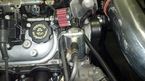
Look closely at the first picture - I made a 3/8" tube to run the length of the driver's side valve cover then under the throttle body. Then it loops into the catch can before going into the intake. The passenger side cover has the little filter for the intake. We'll see how it works out.
 GeoffP
68 Camaro - LS1/T-56
04-27-2012 #15
Registered User
- Join Date
- Sep 2010
- Location
- Santa Clara, CA
- Posts
- 622
Very interesting. Thanks, Geoff!
Steve
05-29-2012 #16
Registered User
- Join Date
- Jan 2006
- Posts
- 86
Im a little confused. I would expect that all three tubes (driver valve cover, pass valve cover and valley cover) should all be routed to the air intake just prior or after the throttle body. Any air pressure that needs to be vented from the crankcase would be as a result of blowby and pumping action of the pistons moving up and down??? Originally Posted by sjaroslo

Update:
After much web surfing, reading and a few phone calls, I have it figured out. There needs to be fresh air in and dirty air out so acids etc... dont build up in the crank case.
In order to do this there needs to be a pressure difference and that is provided by having fresh air (passenger valve cover) come in from somwhere in front of the throttle body (a slight vacum) and dirty air (driver side valve cover and if your motor has it the lifter valley cover) being pulled out from somewhere behind the throttle boday (much higher vacum)
That is a very simplified but practical answer. Depending what year your LS motor is will determine if you need a PCV valve inline.
Norris Motorsports has some info about what year motors need a sepperate PCV valve on his website. He was also very helpful on the phone!
02-11-2013 #17 Registered User
- Join Date
- Sep 2010
- Location
- Beach Park IL
- Posts
- 3,029
It seems related so I will ask here. The fixed orifice is in both the valley cover AND the valve covers? When dealing with aftermarket valve covers do those hose connections need to be dialed down to that orfice size? A port in a stock cover measures .105", I haven't measured a valley cover port yet.
So I guess the question is this, when dealing with a stock LS3 with the stock valley cover and dirty air hose running to the throttle body, does it matter what is in the valve covers as long there is some source to get fresh air into the engine and that the air comes from the air intake between the MAF and the throttle blade?Donny
Support your local hot rod shop!

 Reply With Quote


