

Results 21 to 40 of 73
-
04-11-2012 #21

 -Moderator-
- Join Date
- Apr 2005
- Location
- USA
- Posts
- 4,462

Part Five : Brake Bracket Bolts
Also note ,
On the original / stock setup , one of the bolts that fastened the brake bracket to the spindle doubled as a bolt that fastened the steering arm to the spindle . ( both bolts actually fastened the steering arm )
With the Tru Turn System , the steering arms are fastened to spindle by the , afformentioned shaved nuts and bolts .
But if you are using a stock brake bracket , it still attaches to the original holes as it did from the factory ..
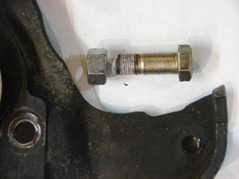
The original factory brake bracket bolts were fairly long because they went through the bracket , knuckle , and steering arm .
So , the original bolts could not be used in these brake bracket holes anymore ..
Anyway , I got some grade 8 shanked bolts and cut them to length and locktighted them appropriately.
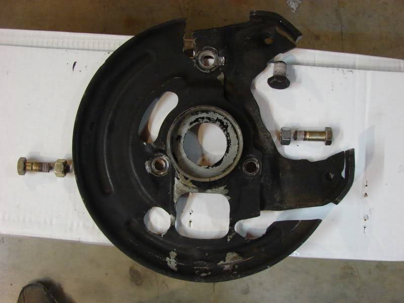
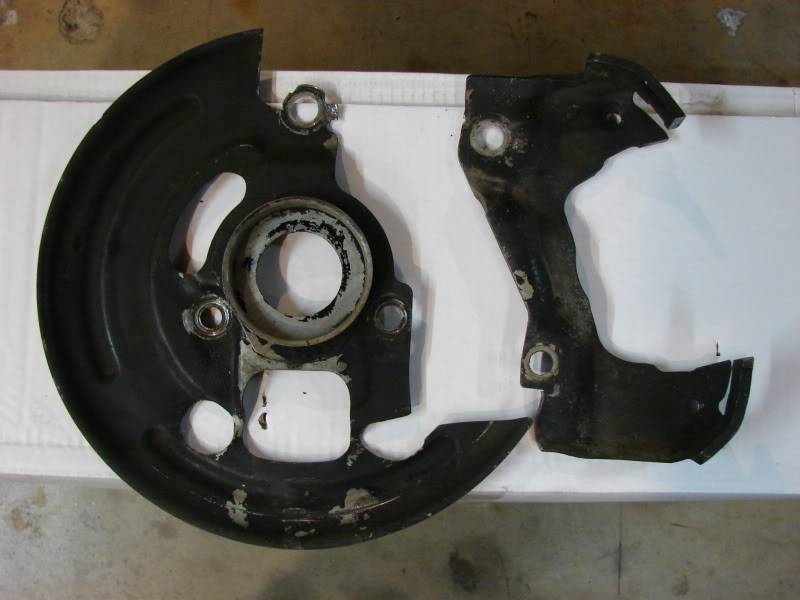
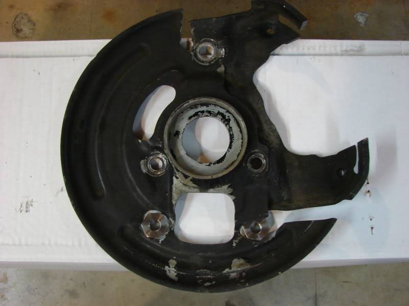
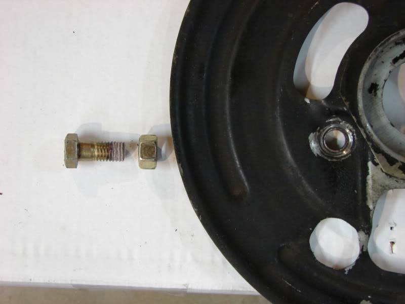
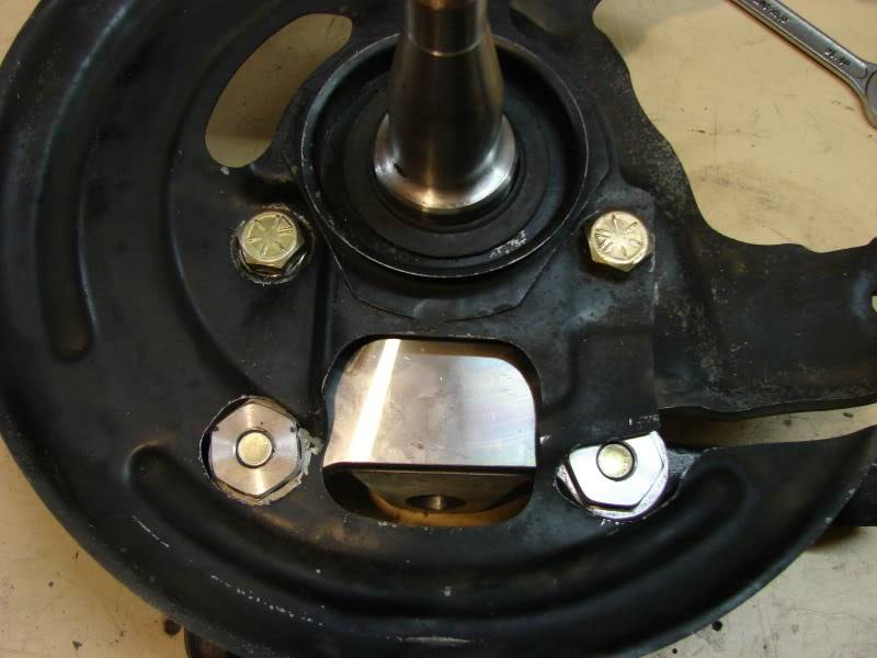
Notice the deep shank on this bolt , if you use an unshaked bolt in this position , the brake bracket will be allowed to move . Make sure to use a shanked bolt ..and locktite !!

Here's a picture of the whole thing bolted together .
Last edited by JEFFTATE; 04-11-2012 at 11:11 AM.
Jeff Tate
U.S.A.
"The best thing about participating in these events is that you get to hang out with a group of intelligent like minded people who live to achieve things in their lives. You won't find a lazy, mean, or dumb bone in their bodies." Bret Voelkel, RideTech
-
04-17-2012 #22 Registered User
- Join Date
- Jun 2009
- Location
- Central FL
- Posts
- 1,231
Jeff, quick question, what size wheels/tires are those in the first few pics?
Dan
04-18-2012 #23
-Moderator-
- Join Date
- Apr 2005
- Location
- USA
- Posts
- 4,462
The wheels that I currently have are American Racing Torque Thrust II's ( purchased in 2003 ).
The fronts are 17 x 8 with 5" backspacing , with a 245/45/17 tire.
The rears are 17 x 9.5" with 5 3/4" backspacing , with a 275/40/17 tire .
PLEASE NOTE :
These wheels are not my optimum choice , I bought them several years ago ( before I knew better ).
Currently , if I was building a '69 Camaro from scratch , I'd minitub the car ( front and rear tubs ) , use 18" wheels with a 275 ( or 295 ) tire up front , and a 335 ( or 345 ) tire in back ... The wider tire , the more grip ..
But the 17's are still in good shape , and I don't have the funds to upgrade yet , plus they actually work with the Tru Turn Steering System.
So , they are gonna get used ..Jeff Tate
U.S.A.
"The best thing about participating in these events is that you get to hang out with a group of intelligent like minded people who live to achieve things in their lives. You won't find a lazy, mean, or dumb bone in their bodies." Bret Voelkel, RideTech
04-22-2012 #24
-Moderator-
- Join Date
- Apr 2005
- Location
- USA
- Posts
- 4,462
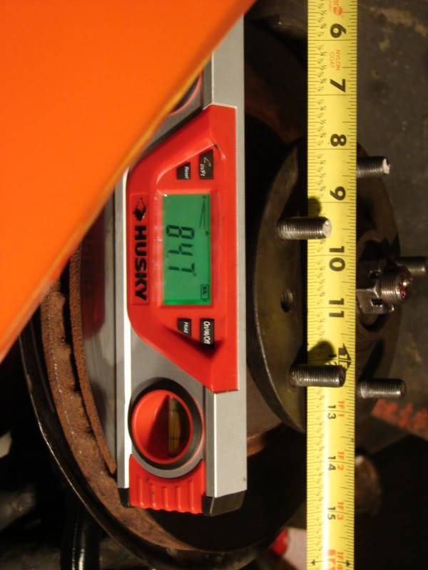
Part Six : Measuring Stock Camber Curve .
I wanted to get measurements of the camber through the suspension travel , before and after the TruTurn install .
So , I started with the stock measurements .
I took the front coil springs out and moved the suspension all the way from fully drooped ( extended ) to all the way up (compressed ). And measured about every inch of travel .
Now , keep in mind that my car only had about 6 inches of suspension travel with this stock configuration.
And with the car at ride height ( The car being lowered with cut springs ) I only had about 1 inch of suspension travel before it was on the bumpstops . So the stock/lowered suspension bottomed out pretty quickly , resulting in little negative camber gain , loss of grip and understeer .
It would overpower the available grip of the front tires and slide across the ground ..
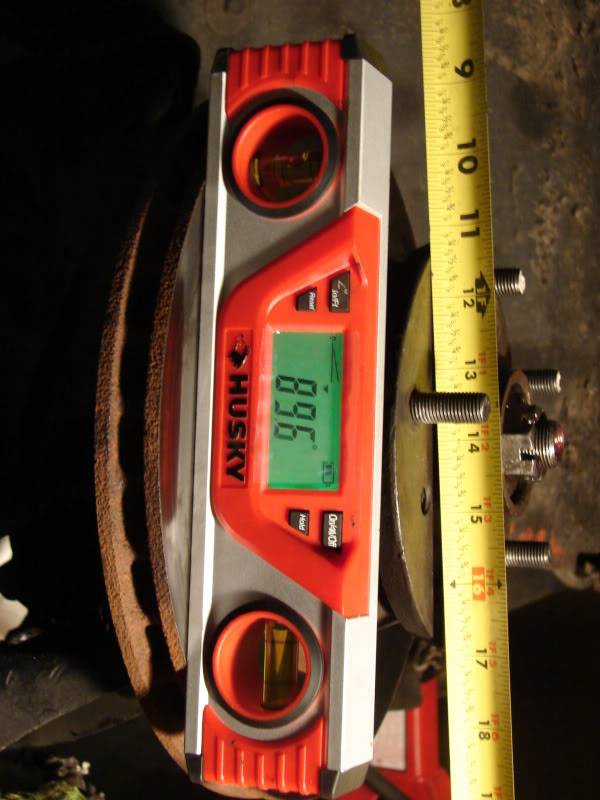
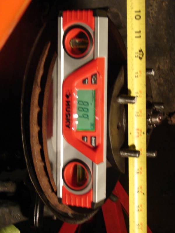
The following 7 pictures will show what the camber gain was with the stock spindle and the Guldstrand Mod .
All the way extended. 1.5+ Camber
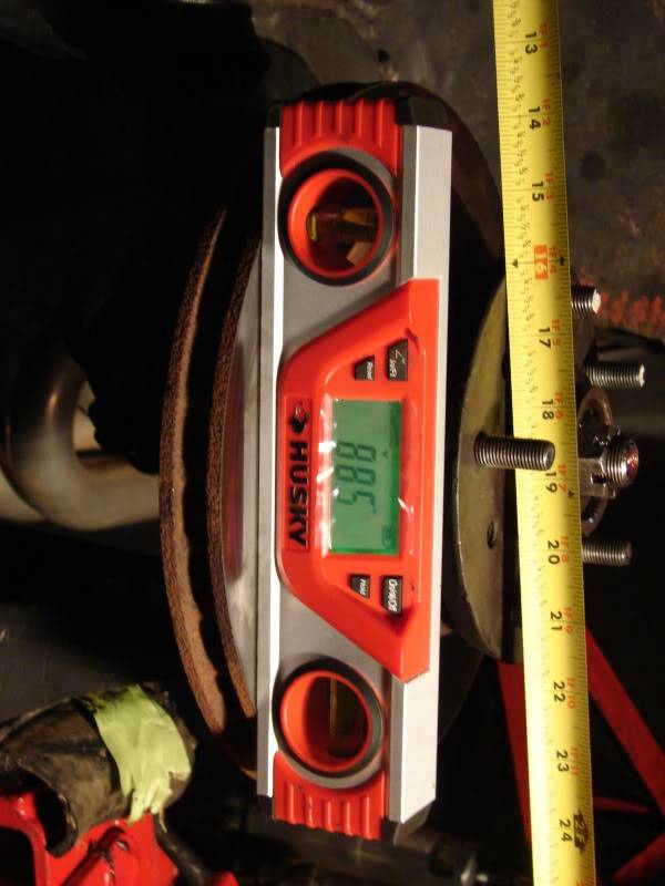
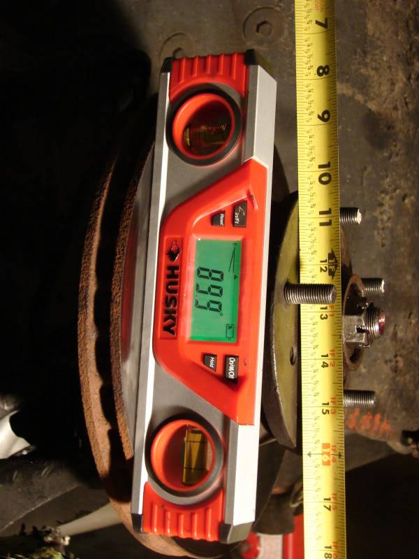
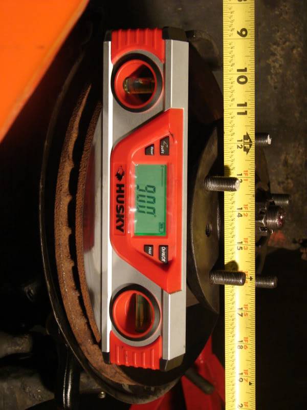
1"compressed. 1.7+ Camber

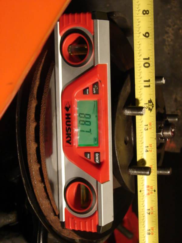
2"compressed. Still 1.7+ Camber

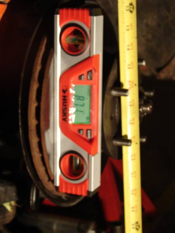
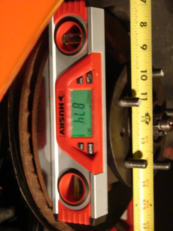
3"compressed. 1.4+ Camber
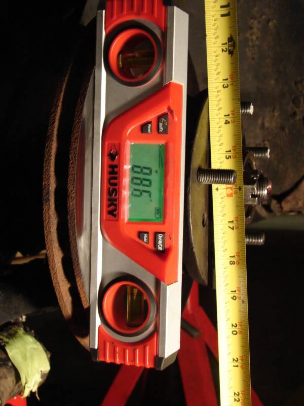
4"compressed. 1.0+ camber

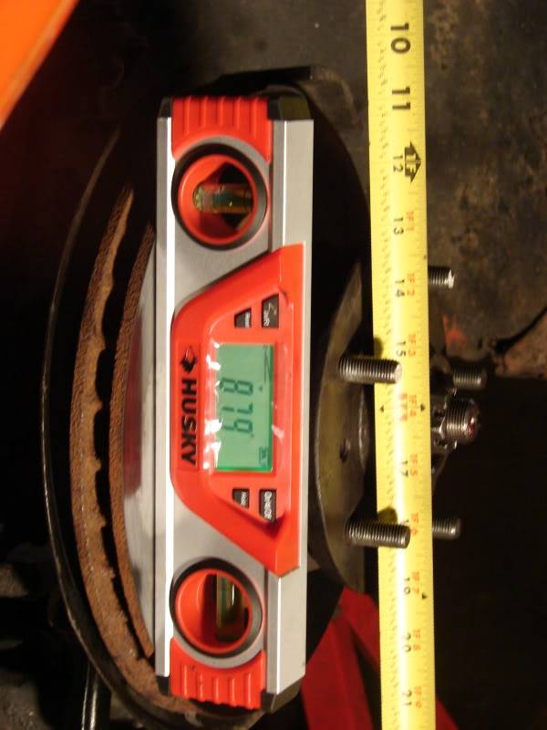
5"compressed. .4+ Camber
Fully compressed. .1- Camber ! Finally some negative camber .
As you can see , I didn't get negative camber until the suspension bottomed out on the bumpstops .
Now , another thing to consider is that the car was on 4 jackstands when I measuerd this , so the actual numbers may not be 100% accurate .
The car may not have been at the exact angle as it would be with the tires on it , while on the ground .
But you get the idea , very little negative camber was generated by the stock setup ..
Plus I had little suspension travel to let the suspension be compliant and work ..Last edited by JEFFTATE; 04-29-2012 at 05:09 PM.
Jeff Tate
U.S.A.
"The best thing about participating in these events is that you get to hang out with a group of intelligent like minded people who live to achieve things in their lives. You won't find a lazy, mean, or dumb bone in their bodies." Bret Voelkel, RideTech
04-29-2012 #25
-Moderator-
- Join Date
- Apr 2005
- Location
- USA
- Posts
- 4,462
Part Seven : Measuring Camber Curve with the Tru Turn Spindles .
Next , I wanted to get a measurement of the Camber Curve with the Tru Turn tall spindles installed ..
With these tall spindles , I got 9 inches of front suspension travel .
All the way extended :(fully drooped) . 4.0+ Camber

1" Compressed. 3.5+ Camber

2" Compressed. 2.9+ Camber
3" Compressed. 2.1+ Camber
4" Compressed. 1.1+ Camber
5" Compressed. 0.0 Camber
6" Compressed. 1.3- Camber
7" Compressed. 2.6- Camber
8" Compressed. 4.1- Camber

Fully Compressed. 5.3- Camber
The Negative Camber reading really jumped up there at the end ..Last edited by JEFFTATE; 06-05-2012 at 12:03 PM.
Jeff Tate
U.S.A.
"The best thing about participating in these events is that you get to hang out with a group of intelligent like minded people who live to achieve things in their lives. You won't find a lazy, mean, or dumb bone in their bodies." Bret Voelkel, RideTech
04-29-2012 #26 Registered User
- Join Date
- Jan 2006
- Posts
- 1,747
It sure did! Mine are installed - guessing yours are too and that you're just formatting these posts to make them pretty!
 Great job on this BTW!!!
GeoffP
Great job on this BTW!!!
GeoffP
68 Camaro - LS1/T-56
04-30-2012 #27
-Moderator-
- Join Date
- Apr 2005
- Location
- USA
- Posts
- 4,462
I'm not done yet ..
Jeff Tate
U.S.A.
"The best thing about participating in these events is that you get to hang out with a group of intelligent like minded people who live to achieve things in their lives. You won't find a lazy, mean, or dumb bone in their bodies." Bret Voelkel, RideTech
04-30-2012 #28
-Moderator-
- Join Date
- Apr 2005
- Location
- USA
- Posts
- 4,462
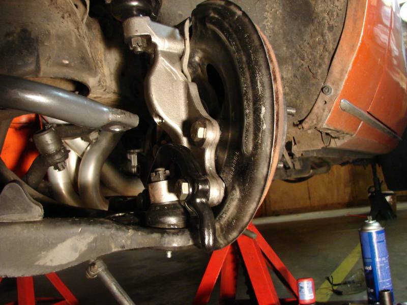
Part Eight: Checking for Balljoint Bind .
While I had the front spring out , and was getting all these camber measurements , I checked for ball joint bind .
I put the suspension all the way up and all the way down and rotated the steering knuckle all the way from lock to lock in every concievable direction ..
I didn't detect any ball joint bind ..
Last edited by JEFFTATE; 05-11-2012 at 11:39 AM.
Jeff Tate
U.S.A.
"The best thing about participating in these events is that you get to hang out with a group of intelligent like minded people who live to achieve things in their lives. You won't find a lazy, mean, or dumb bone in their bodies." Bret Voelkel, RideTech
05-01-2012 #29
-Moderator-
- Join Date
- Apr 2005
- Location
- USA
- Posts
- 4,462
Yes , I'm just doing the install thread in stages .. to keep it straight in my brain . Originally Posted by GeoffP
 Jeff Tate
U.S.A.
"The best thing about participating in these events is that you get to hang out with a group of intelligent like minded people who live to achieve things in their lives. You won't find a lazy, mean, or dumb bone in their bodies." Bret Voelkel, RideTech
05-01-2012 #30
-Moderator-
- Join Date
- Apr 2005
- Location
- USA
- Posts
- 4,462
Part Nine: Control Arm Angles , Sway Bar Links , Trimmed Bumpstops ..
As I've already stated , I've gotten more suspension travel with the Tru Turn tall/drop spindle .
This is because , with the outer ball joints further apart , there is more distance between the two bump stops , so , there's where more suspension travel comes from .
Also with the drop spindle design , I'm starting out with the lower control arm at a more desirable angle than it was with the stock arms .
With the stock ( lowered ) setup at the desired ride height , the lower control arm was just about level .
In other words , the lower ball joint was at the same height as the lower control arm bushings.
With the 1 1/2" drop spindle , I'm gaining some of that lowering with the spindle design , so the lower arm is back to an angle where it can move through the camber curve better .
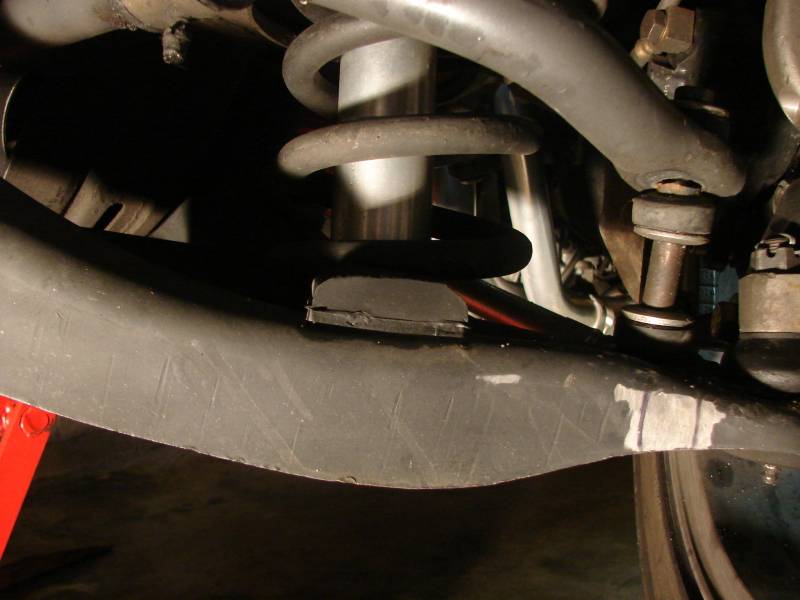
If you look in the following pictures , you will see that the lower bump stop is a few inches away from the frame .
With the stock setup , it was 1/2" from the frame .
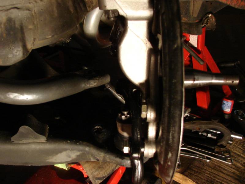
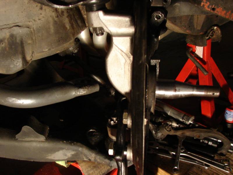
Also , I had to change the length of the swaybar endlinks to get the swaybar about level .
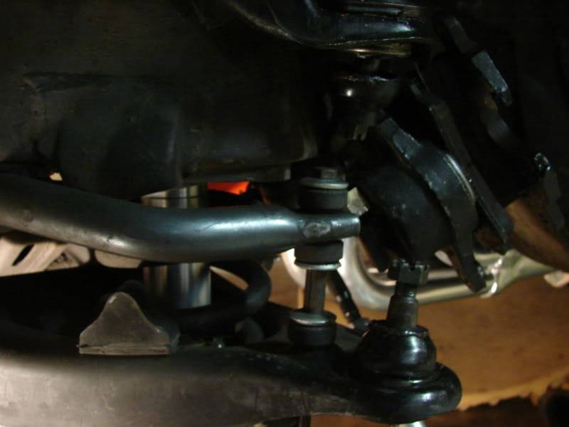
I went ahead and trimmed the lower bumpstops to take advantage of the extra negative camber gain .
That way , the wheel can travel further up in the wheelwell and get into that negative camber zone .
But I left enough bumpstop there to keep the shock or the tire from bottoming out .
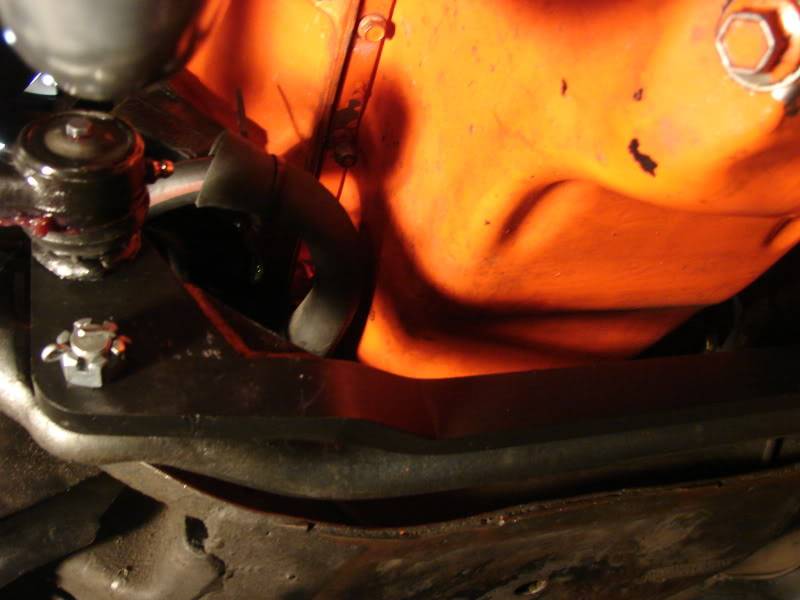
Here's a couple of pics of the trimmed bumpstops.
Notice the bare metal spots close to the ball joint , I was thinking of welding steering stops there , but so far haven't needed them . The tire only barely scrubbs if turned all the way to lock , which I only do while parking .
Last edited by JEFFTATE; 05-11-2012 at 11:45 AM.
Jeff Tate
U.S.A.
"The best thing about participating in these events is that you get to hang out with a group of intelligent like minded people who live to achieve things in their lives. You won't find a lazy, mean, or dumb bone in their bodies." Bret Voelkel, RideTech
05-01-2012 #31
-Moderator-
- Join Date
- Apr 2005
- Location
- USA
- Posts
- 4,462
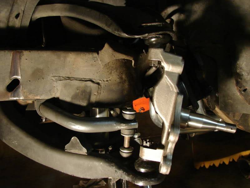
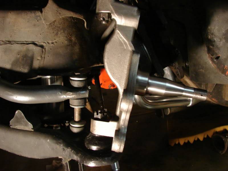
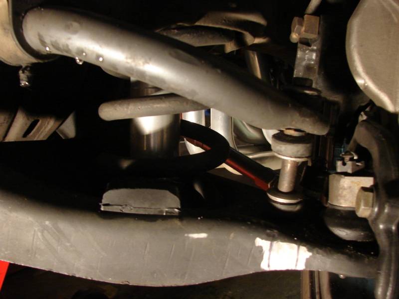
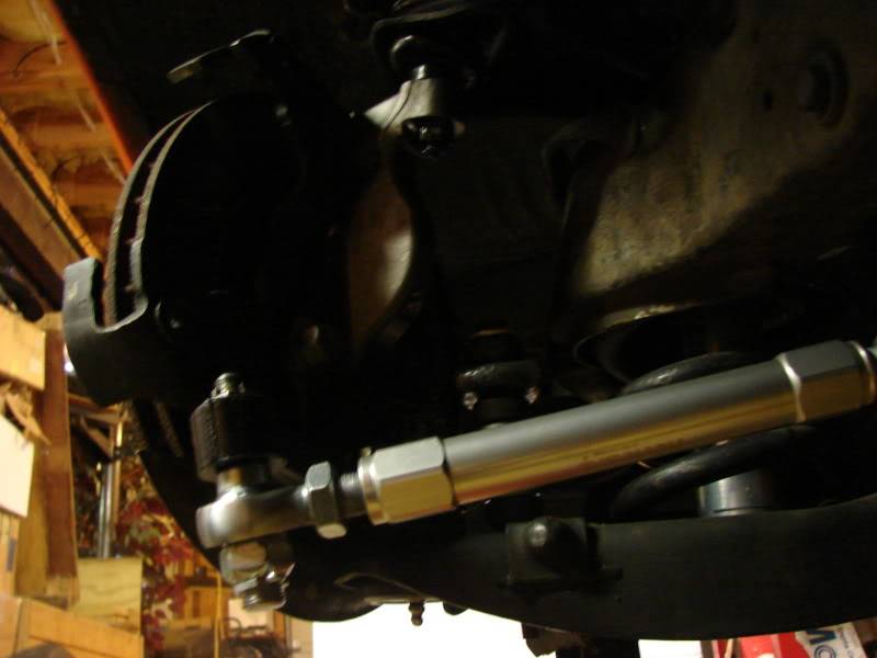
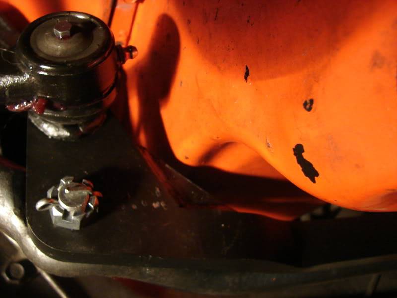
Part Ten : Billet Tie Rod Adjusters , Inner tie-rod end draglink relocating bracket .
The Tru-Turn came with ridetech's great Billet Tie Rod Adjuster sleeves .
These adjusters are so nice and are ten times easier to move than the old stock type adjusters .
They are very smooth .
I like the flat joint on the outer link too , it saves space between it and the wheel .
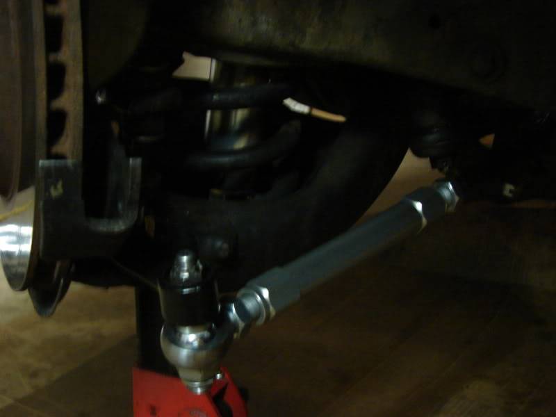
The inner tie rod end draglink relocating bracket attaches to the existing center link.
Just make sure you follow the illustrated directions correctly when you put this on ..
Make sure you get the tapered pins , washers , and cotter pins all in place !
One concern of mine was whether this draglink relocating bracket would clear my oil pan ,
It did .
Last edited by JEFFTATE; 05-02-2012 at 10:01 AM.
Jeff Tate
U.S.A.
"The best thing about participating in these events is that you get to hang out with a group of intelligent like minded people who live to achieve things in their lives. You won't find a lazy, mean, or dumb bone in their bodies." Bret Voelkel, RideTech
05-02-2012 #32
-Moderator-
- Join Date
- Apr 2005
- Location
- USA
- Posts
- 4,462
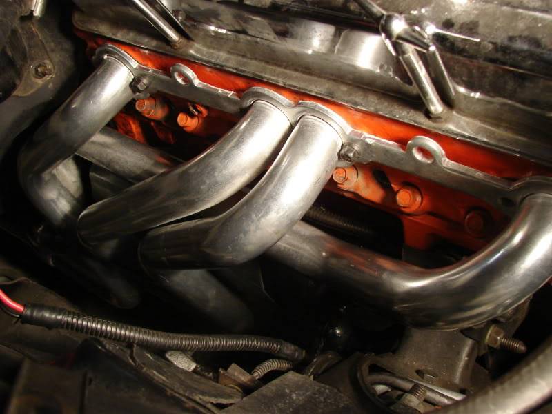
Part Eleven : HEADER Clearance !!
One thing that was an interference fit on the car was the clearance between the passenger side header and the inner tie-rod end .
With the TruTurn System , the inner tie rod end is moved up and rearward due to the thickness of the center relocating bracket , ( this upward relocation is done to help correct bump-steer ).
This is with a set of Hooker Super Comp Jet Hot Coated 1 3/4" tube headers on a small-block Chevy Engine ..
I made marks on the header where the interference took place .
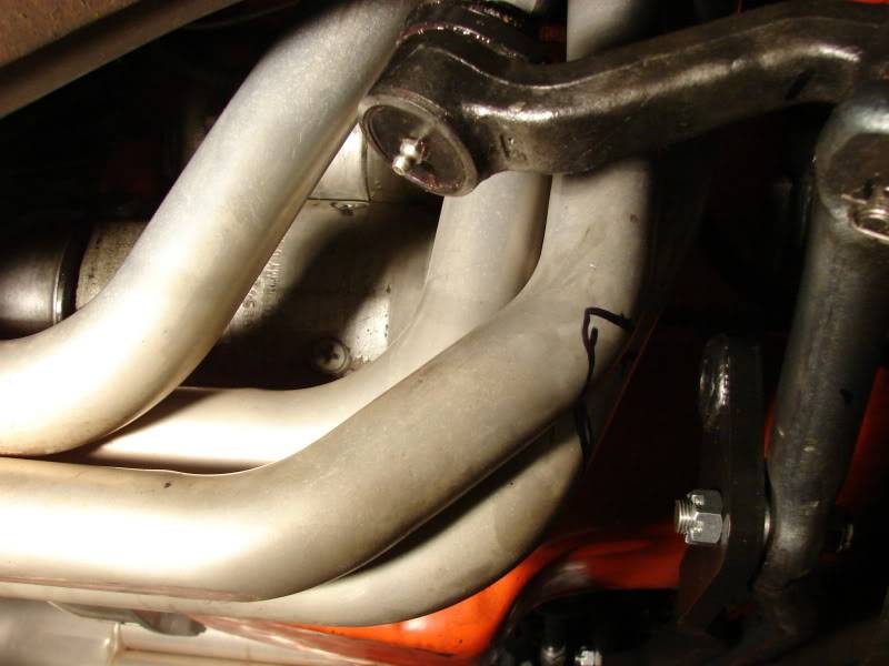


I thought about having the passenger side header cut and modified , but after leaving it at a custom fabrication shop for two weeks without them ever working on it , ( and with a cost of $200 to modify it , plus more money to recoat it ) , I decided not to ruin it by cutting it up. I hated to hurt that beautiful Jet Hot coating ..
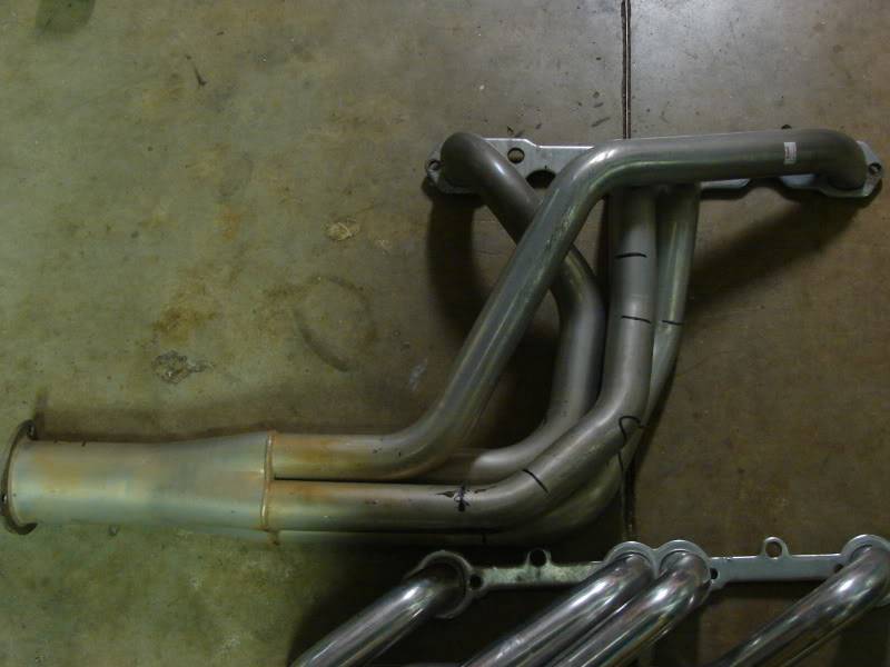
I decide to buy a different set of headers and just sell the Hooker Headers .( They had too big of a primary tube size for a stock 350cui engine anyway , I bought them years ago with the intention of upgrading to a 383cui )
So , I bought a set of Summit Brand ceramic coated 1 5/8" primary tube headers .
They are routed differently ( kind of a swept back design )
Here's some comparison pics of the Hooker Super Comp above the Summit Brand .
Notice the straight line in the concrete to give a reference to the interference area .

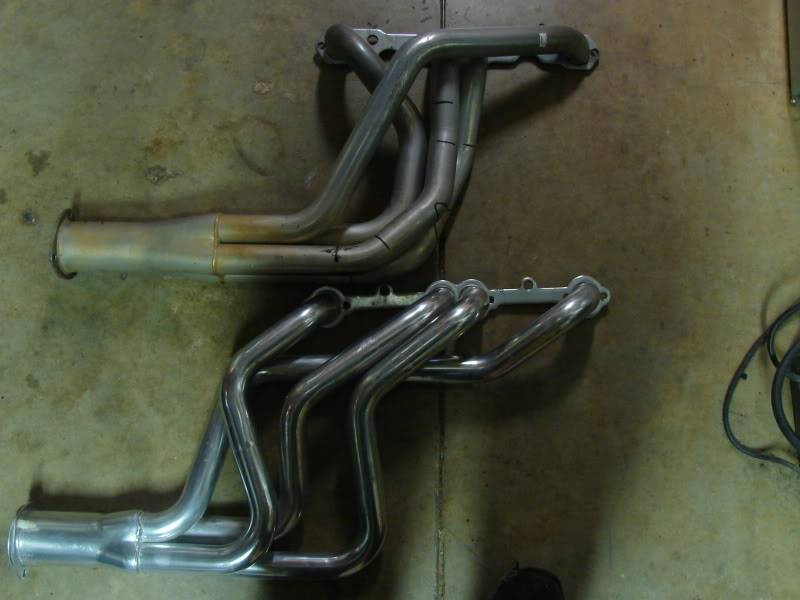

Of course , I did have to cut , reposition , and reweld the collectors on the exhaust .
I do not have a great deal of welding expertise , but I have always been determined to do everything I can by myself . ( it's a pride thing )
So , I taught myself to weld my exhaust .
I'm not posting any pictures . Lets just say it's " functional " , but not pretty .. leave it at that ..
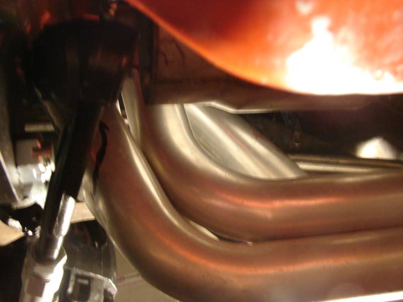
The passenger side header was routed a little closer to the engine , so I had to re-route the starter wiring and I made a heatshield for the starter ( by myself ) , because I just didn't like any of the store bought heatshields ..
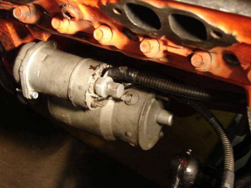
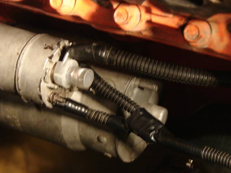
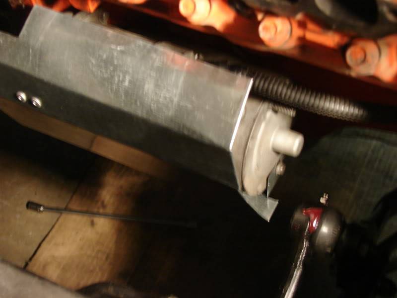
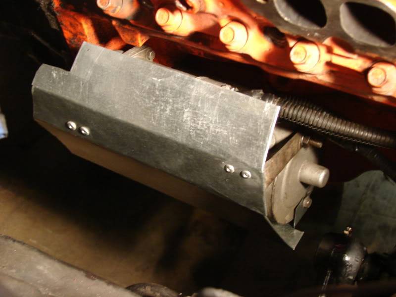
Here's a final install pic of that pass side header .
Last edited by JEFFTATE; 05-02-2012 at 07:03 AM.
Jeff Tate
U.S.A.
"The best thing about participating in these events is that you get to hang out with a group of intelligent like minded people who live to achieve things in their lives. You won't find a lazy, mean, or dumb bone in their bodies." Bret Voelkel, RideTech
05-02-2012 #33 Registered User
- Join Date
- Jan 2007
- Location
- CT
- Posts
- 782
excellent...Thank you very much for the header information. Was there any driver side interference?
________________
Nick S.
Gold/Gray 1967 Camaro
05-02-2012 #34
-Moderator-
- Join Date
- Apr 2005
- Location
- USA
- Posts
- 4,462
There was no interference on the drivers side with either the Hooker or Summit headers . Originally Posted by nicks67camaro
Jeff Tate
U.S.A.
"The best thing about participating in these events is that you get to hang out with a group of intelligent like minded people who live to achieve things in their lives. You won't find a lazy, mean, or dumb bone in their bodies." Bret Voelkel, RideTech
05-08-2012 #35
-Moderator-
- Join Date
- Apr 2005
- Location
- USA
- Posts
- 4,462
Part Twelve : Hidden Ride Height Adjuster Modification
My Camaro still has factory style front coil springs . ( Although mine are 700# Landrum Springs ).
I'm using some of the AFCO Ride Height Adjusters that have been mounted in the upper spring pocket .
One problem that I've had over the years is that the springs are 5" outside diameter ( like they are supposed to be ) , but the inside diameter was larger than the spring adjuster .
So , the spring would walk it's way over to one side and rub on the spring pocket ( occasionally )
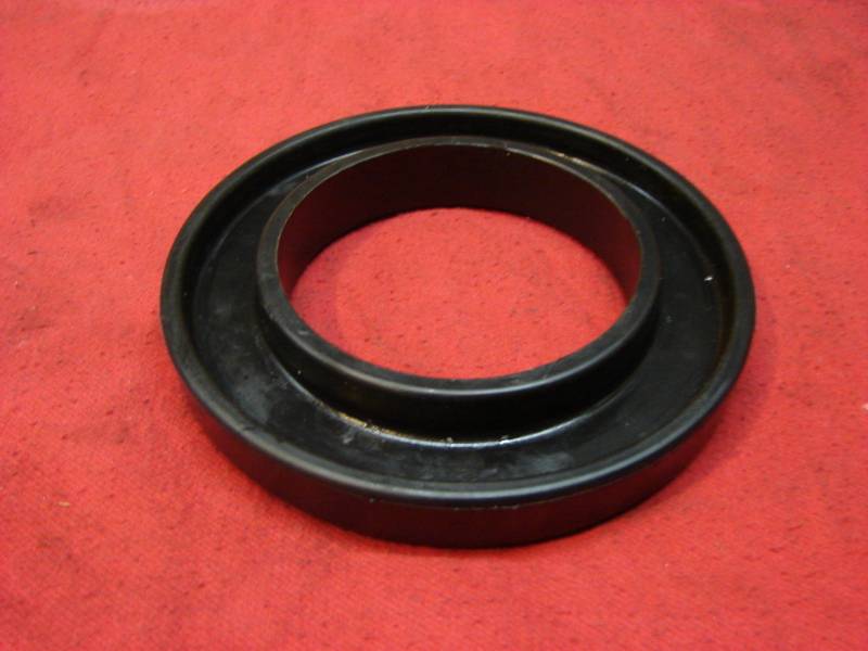
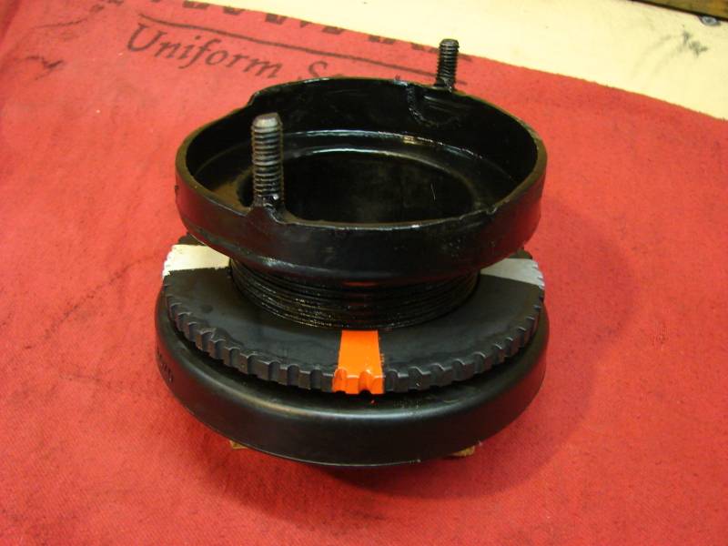
So , I put a urethane spring spacer on the spring that hugs the ride height adjuster ..
Now the spring stays centered !!
Another problem was that the QA1 shocks are larger diameter than the old factory shocks ..
As the lower control arm swings through it's travel , the bottom mounting point of the shock moves in an arc ..
This arc causes the side of the shock to rub against the inside of the spring adjuster and then move away again ..

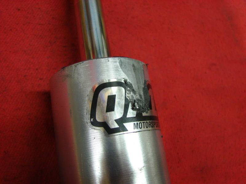
The solution was to move the hidden spring adjuster all the way to the outside of the upper spring pocket , instead of mounting it in the very center .. ( Only about 1/8 " more towards outside , but it gave the needed clearance ) .
These spring adjusters gave me the ability to fine tune the front ride height , but to adjust them , I had to remove the shocks , dsiconnect the swaybar , and disconnect the lower balljoint .
Then pull the spring out and turn the plate .
Then re-assemble ..
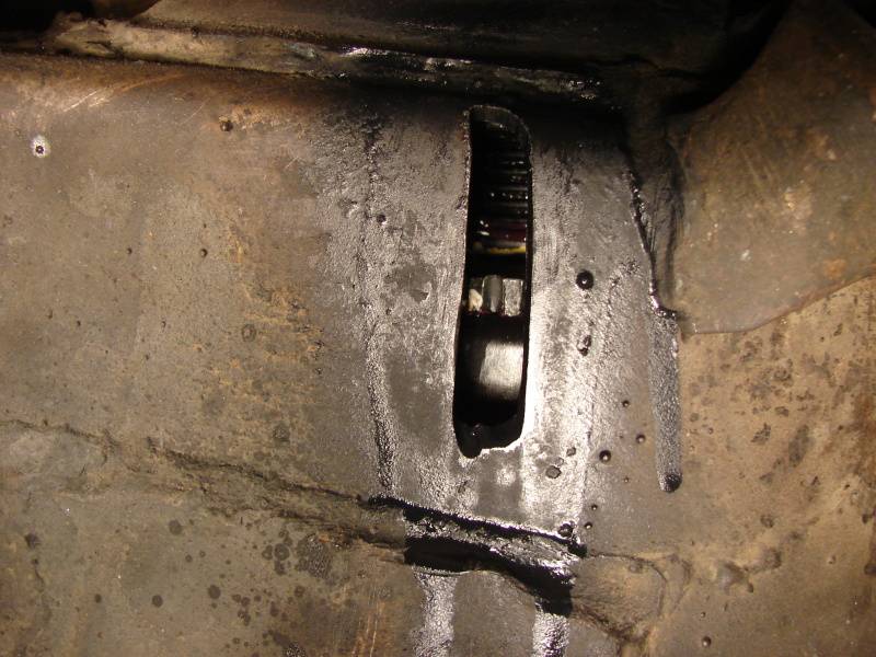
I decided to cut slots in the subframe , on the outside if the spring pocket , to reach in with a screwdriver or prybar and adjust them , . ( kinda like a drum brake adjuster )
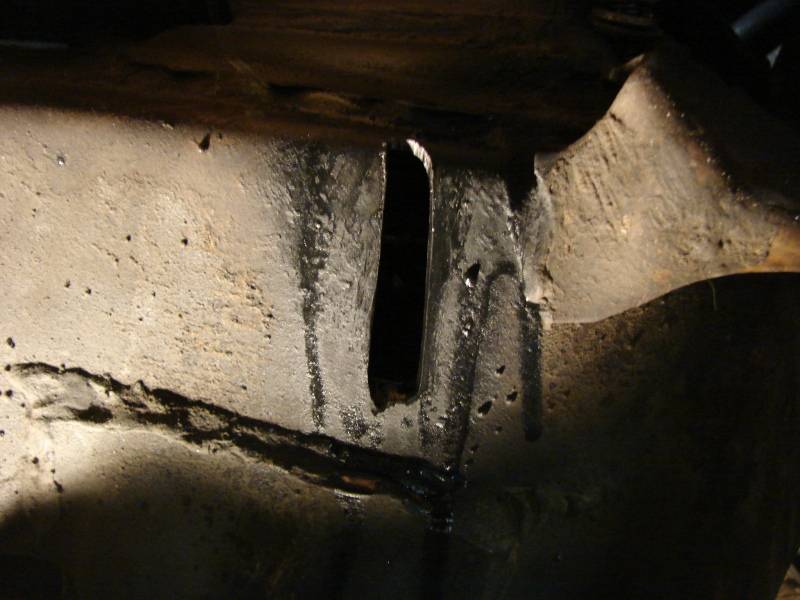


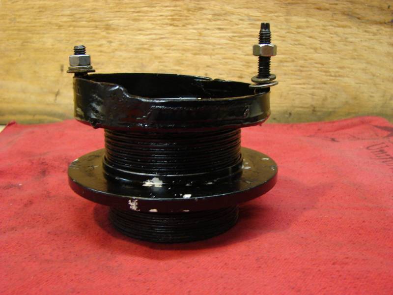
This also required that I cut notches all the way around the adjuster plate .( 63 to be exact )

And then I painted different color stripes on the adjuster plate so I could tell when the plate had completed one turn ( or 1/4 turn , or 1/2 turn ) . You can see the colors through the slot in the subframe .
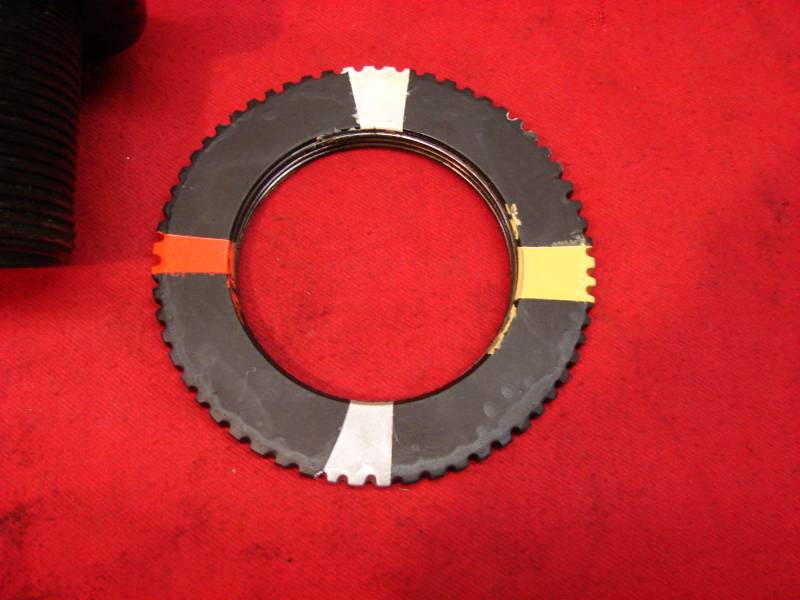

Now here is a picture of the slotted , painted assembly , with the urethane spring spacer ( for centering ) installed .

And here's a pic looking through the slot at spring adjuster .
I still can't adjust the ride height while there is full weight on the front suspension , BUT , I can adjust it by jacking up the car and taking some of the pressure off the front springs , then sticking a prybar in the slot .
They are quite hard to turn , but it beats all the disassembly I use to have to do ..Last edited by JEFFTATE; 05-08-2012 at 12:59 PM.
Jeff Tate
U.S.A.
"The best thing about participating in these events is that you get to hang out with a group of intelligent like minded people who live to achieve things in their lives. You won't find a lazy, mean, or dumb bone in their bodies." Bret Voelkel, RideTech
05-08-2012 #36 Registered User
- Join Date
- Jun 2009
- Location
- Piqua, Oh
- Posts
- 397
Are you using the Guldstrand Mod when your checking this? Originally Posted by JEFFTATE
Mike South
1968 Camaro SS/RS LS1/T56
Ride Tech Tru Turn, Ride Tech T/Q Coil-overs
Ride Tech 4-link
05-08-2012 #37
-Moderator-
- Join Date
- Apr 2005
- Location
- USA
- Posts
- 4,462
Yes , the car has had the Guldstrand Mod for several years. Originally Posted by BuzzKillian
And I left the upper arms mounted in that position .Jeff Tate
U.S.A.
"The best thing about participating in these events is that you get to hang out with a group of intelligent like minded people who live to achieve things in their lives. You won't find a lazy, mean, or dumb bone in their bodies." Bret Voelkel, RideTech
05-09-2012 #38
Registered User
- Join Date
- Jan 2006
- Posts
- 1,747
Jeff do you think the camber gain is too aggressive with the Guldstrand Mod and tall spindles?
GeoffP
68 Camaro - LS1/T-56
05-09-2012 #39
-Moderator-
- Join Date
- Apr 2005
- Location
- USA
- Posts
- 4,462
I don't know the answer to that question Geoff . I don't have a suspension design background to know the difference . Originally Posted by GeoffP
I have driven the car a good bit ( and done a track event , and driven back and forth about 800 miles roundtrip to the event ) .
The front grip is much better .
I haven't seen any sign of uneven tire wear.
I figure if the G-Mod was too aggressive for this tall spindle , I'd lose grip becasue the tire was tilted in too far under compression .
But that hasn't happened .
It seems to be ok .Jeff Tate
U.S.A.
"The best thing about participating in these events is that you get to hang out with a group of intelligent like minded people who live to achieve things in their lives. You won't find a lazy, mean, or dumb bone in their bodies." Bret Voelkel, RideTech
05-11-2012 #40
-Moderator-
- Join Date
- Apr 2005
- Location
- USA
- Posts
- 4,462
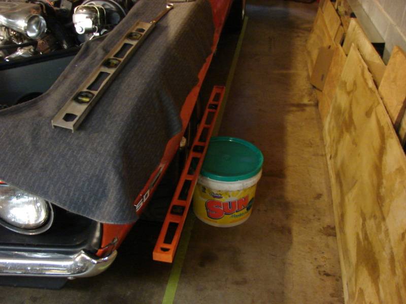
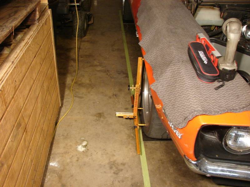
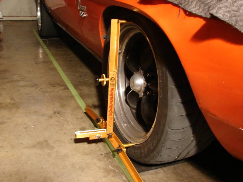
Part Thirteen: Alignment at Home !
Yes , I do my own alignments .
Call me a glutton for punishment , call me a nut , But I enjoy learning new skills and making sure it's done right .
It would probably save money and time to have a local shop do it , but I trust almost no one with my car.
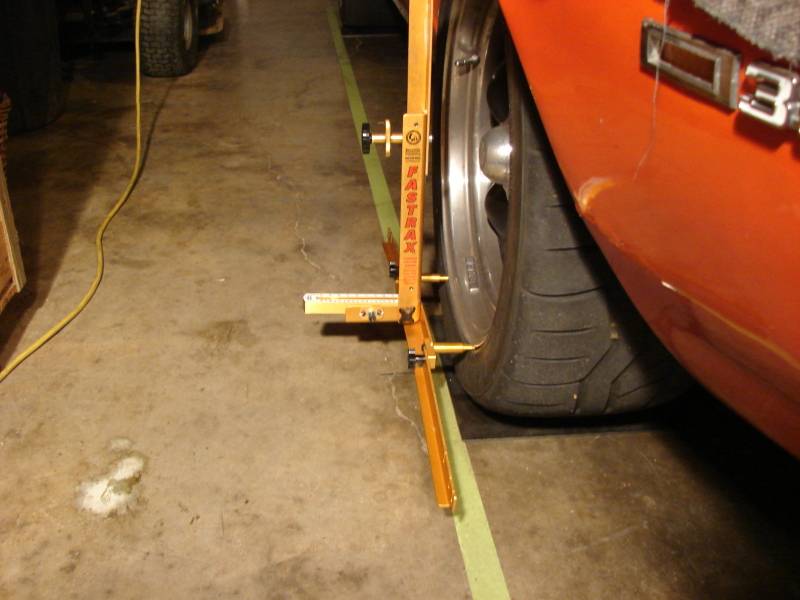
So , I have an SPC ( Specialty Products Company ) alignment gauge . It works pretty good if you get it calibrated right and follw the directions .
I have had the alignment on the Camaro checked after I've done it at home , and it was within 10% of a digital alignment machine ..So , it's accurate enough .
Also , when I do it myself , I can experiment with different settings .
I tape off a nice square on the level floor , use a long straight edge , some greased steel plates for turntables , and the alignment gauge , and in a few trial and effort sequences , and a few test drives , I'm done .
( Actually it took me several evenings after work , an hour or two at a time )
I was able to get ,
On the Drivers Side :
1 degree negative Camber
4.1 degree's positive Caster
On the Passengers Side :
1.1 degree's negative Camber
4.3 degree's positive Caster
and Toe : 1/16 " IN
With these settings , the car doesn't drift and the steering is sharp.

Last edited by JEFFTATE; 05-11-2012 at 12:15 PM.
Jeff Tate
U.S.A.
"The best thing about participating in these events is that you get to hang out with a group of intelligent like minded people who live to achieve things in their lives. You won't find a lazy, mean, or dumb bone in their bodies." Bret Voelkel, RideTech

 Reply With Quote


