


Results 1 to 20 of 24
-
01-11-2012 #1

 Registered User
- Join Date
- Mar 2008
- Location
- Brisbane Australia
- Posts
- 410

Torque Arm 3 link Cantilever rear coilover idea
Hey All, I have a pickup that I like to use as a bit of a low buck development mule for my Australian Chrysler Valiant (think Dodge Dart).
I've been thinking about a rear suspension upgrade for a while and would like to do something both interesting and functional and the idea of locating the shocks longitudinally along the chassis rails really appeals to me. (keeping weight both low and forward) I'm happy to do the fab work where required so I don't fear having to make the parts that don’t already exist.
My plan for the 3 Link is similar to the GM F Body torque arm set up but the links on the side would look like the letter L from the side. Disregarding the gussets. For the centre torque arm I'll probably just adapt an aftermarket piece like the sphoon ones.
I know there’s lots of clever people on here so I'd love to have my ideas pulled apart before I do any fab work.
Here's sketch I just did in an effort to explain my ramblings. (not in the drawing is some sort of diff centring device, I'd most likely run a watts link as thats whats under my leaf sprung dart)

Thanks for lookingHot rodder's recycle, wheres those prius' going when the tree huggers have a new fad.
-
01-12-2012 #2 Registered User
- Join Date
- Oct 2009
- Location
- New Derry, PA
- Posts
- 1,265

A couple of things to do some more thinking about...
THe pivot points of the links (corner of the L) have to hold the links upright. THey can't be allowed to move side to side, or the springs will shove them whatever direction they feel like. All the spring knows is it wants to be LONGER... That means huge mounts and roller bearings or solid bushings at the corner, which means the links are restricted to pure vertical motion. The axle however, is going to want the links to twist so it can roll. Your only real option here is really big soft rubber bushings at the axle end. Did Ford ever sell twin I beam axle pickups with front leaf springs in OZ? If so, you'll know what type of rubber bushings I'm referring to?
The links themselves will be carrying all the weight of the rear of the vehicle. You can get away with this, but I would make a full triangle out of them, rather than leave half the link un-supported. Honestly, it's not the greatest idea for handling or load carrying. Kinda neat for being different, but not too practical.
Ray Kaufman - Wyotech Chassis Fab and High Performance Instructor. Words of Wisdom from an old master... at Asylum Custom Interiors website
01-12-2012 #3 Registered User
- Join Date
- Apr 2009
- Location
- san diego
- Posts
- 5,101
I agree with Ray, the lower link chassis mount has to be a solid busing not a heim joint. I think this system will have lots of roll bind or at least roll resistance not due to roll center, CG and springs rate.
I will draw something up similar and post it here. It will reduce the roll bind and increase the fab but also increase the cool factor.My build thread: https://www.pro-touring.com/showthre...ing&highlight=
The mustang build thread: https://www.pro-touring.com/showthre...el)&highlight=
01-12-2012 #4
Registered User
- Join Date
- Apr 2009
- Location
- san diego
- Posts
- 5,101
Here you go a quick sketch....
The lower link still carries all the rear weight of the car and needs to be designed to prevent beam bending.My build thread: https://www.pro-touring.com/showthre...ing&highlight=
The mustang build thread: https://www.pro-touring.com/showthre...el)&highlight=
01-12-2012 #5 Registered User
- Join Date
- May 2002
- Location
- Northern California
- Posts
- 10,716
i like this set up too....
 MrQuick ΜΟΛ'ΩΝ ΛΑΒ'Ε
01-12-2012 #6
Registered User
- Join Date
- Mar 2008
- Location
- Brisbane Australia
- Posts
- 410
Thanks for the reply, very good points too. The design I posted would only work with something like a solid aluminum bushing at the front and as you mentioned the bushing ay the diff would need to be very soft to stop the whole thing from binding during travel. The other way to control side to side movement of the upper shock mount would be to make the upright of the L shorter but that would also change the ratio acting on the shock. Originally Posted by exwestracer

This one has to fall into the category of sometimes simple is not better and theres no use in being different for different sake, nice discussion.Hot rodder's recycle, wheres those prius' going when the tree huggers have a new fad.
01-12-2012 #7
Registered User
- Join Date
- Mar 2008
- Location
- Brisbane Australia
- Posts
- 410
Thanks for chiming in Bryce, I was hoping you and exwestracer would make some suggestions as I always find your input very informative. The rational behind my original thinking was to see if a version of this type of suspension was viable without the bell crank but the points you both have made ring very true. Originally Posted by Bryce
Plus I think the sketch you've posted could potentially be easier to package and still has everything low and forward of the axle.Hot rodder's recycle, wheres those prius' going when the tree huggers have a new fad.
01-12-2012 #8
Registered User
- Join Date
- Mar 2008
- Location
- Brisbane Australia
- Posts
- 410
Yeah I love the pirate 4x4 message board just for the fab work and suspension design some of those guys pull off. Originally Posted by MrQuick
Hot rodder's recycle, wheres those prius' going when the tree huggers have a new fad.
01-12-2012 #9
Registered User
- Join Date
- Oct 2009
- Location
- New Derry, PA
- Posts
- 1,265
Bryce, I think you'd still need a solid bushing in there somewhere to prevent the lower arm from rolling over to the side, no? Originally Posted by Bryce
Ray Kaufman - Wyotech Chassis Fab and High Performance Instructor. Words of Wisdom from an old master... at Asylum Custom Interiors website
01-12-2012 #10
Registered User
- Join Date
- Nov 2007
- Posts
- 28

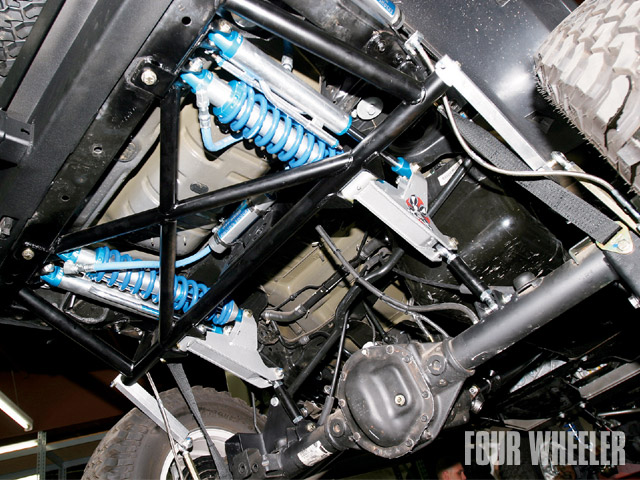
Pretty sure that's a Jeep kit not a one off. Big bucks though.
01-12-2012 #11
Registered User
- Join Date
- Mar 2008
- Location
- Brisbane Australia
- Posts
- 410
That does look more kit than fab but how many kits bolt in any way lol
Hot rodder's recycle, wheres those prius' going when the tree huggers have a new fad.
01-15-2012 #12
Registered User
- Join Date
- Apr 2011
- Posts
- 165
I am looking to do the same thing.
01-16-2012 #13
Registered User
- Join Date
- Oct 2009
- Location
- New Derry, PA
- Posts
- 1,265
hr56,
For a PT application, I think you'd want to move the bellcrank and shock assemblies closer to the ends of the axle housing. Keep in mind that the bellcrank pivots are still bearing all the rear weight, so that area of the frame has to be strong enough to carry the load. Just because the coilovers are laying down doesn't change the physics of where the load is transferred from the axle. Keep us posted, looks like a neat project.
Ray Kaufman - Wyotech Chassis Fab and High Performance Instructor. Words of Wisdom from an old master... at Asylum Custom Interiors website
01-16-2012 #14
Registered User
- Join Date
- Mar 2008
- Location
- Brisbane Australia
- Posts
- 410
HotRod56 I cant see your pic for some reason....
Anyway I figured I'd keep this discussion going and throw some more questions out there. I've noticed while researching this stuff that quite a few guys who are building kit cars and imports are adapting bike coil overs. I think my application may be light enough with some effort to be able to use them as well with some lightening efforts.
While looking for shock options I stumbled onto some interesting info that I think is relevent to this thread.
First this Yamaha R1 Belcrank and dogbone. Keep in mind I've just been web surfing so I've got no idea of the size of these units but they look interesting.
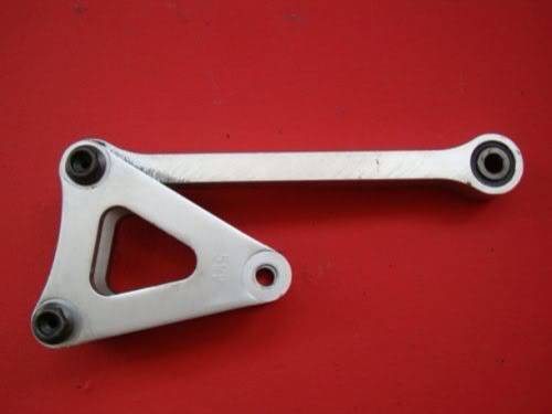
This linkage design is an interesting take on things I haddn't thought of.
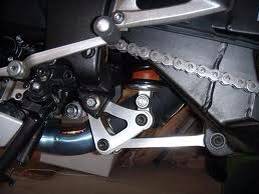
As is this:
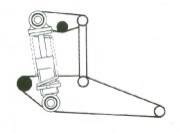
I also stumbled onto this article that gave some really interesting comment in regard to placement etc
http://www.promecha.com.au/leverage_linkages.htmHot rodder's recycle, wheres those prius' going when the tree huggers have a new fad.
01-17-2012 #15 Registered User
- Join Date
- May 2011
- Posts
- 301

This bike shock Idea crossed my mind, this will be intersting, lots of potential and those shocks are often double adjustable and the spring can always be tighten up for extra load, Guys, please feel free to post pros and cons on this set up above.
1972 Nova " Hotwhilz Special"
https://www.pro-touring.com/showthre...t&goto=newpost Under the knife!
01-17-2012 #16
Registered User
- Join Date
- Oct 2009
- Location
- New Derry, PA
- Posts
- 1,265
The bike linkage (in stock form) tends to be very progressive. This stuff was tried on F1 cars back in the late 60s. The spring rate is harder to predict, as shock travel changes for each inch of wheel travel.... Hmmm, like stock coils or leaf springs I guess...
If you plot out spring movement vs wheel movement it should be easy enough to figure out what springs you need. The bike shocks work fine, but the base damping may need to be altered. With a stock bike shock, I'm not sure how easy that would be.
Ray Kaufman - Wyotech Chassis Fab and High Performance Instructor. Words of Wisdom from an old master... at Asylum Custom Interiors website
01-17-2012 #17
Registered User
- Join Date
- May 2011
- Posts
- 301
Wonder if 4" total travel would be a bit on the short side for street use? Wich end of the link would need to be lenghtened / shortened to be more like 6-8" wheel travel, hard to figure with my small head!
Manageable?
Let's hear it! Got some showa shocks with external reservoir, they may do but the travel (4" inch ) got me wondered!1972 Nova " Hotwhilz Special"
https://www.pro-touring.com/showthre...t&goto=newpost Under the knife!
01-17-2012 #18
Registered User
- Join Date
- Apr 2009
- Location
- san diego
- Posts
- 5,101
I only have 4" of rear travel on my falcon. Its okay for me. My DD 95 mustang has 1" of travel before it hits the bumps. With the correct spring rate and shock it works just fine, the huge bumps are a hassle.
My build thread: https://www.pro-touring.com/showthre...ing&highlight=
The mustang build thread: https://www.pro-touring.com/showthre...el)&highlight=
01-17-2012 #19
Registered User
- Join Date
- Oct 2009
- Location
- New Derry, PA
- Posts
- 1,265
Move the shock eye closer to the rocker pivot. Less shock movement per inch of wheel travel. Originally Posted by Hotwhilz
Ray Kaufman - Wyotech Chassis Fab and High Performance Instructor. Words of Wisdom from an old master... at Asylum Custom Interiors website
01-18-2012 #20
Registered User
- Join Date
- Mar 2008
- Location
- Brisbane Australia
- Posts
- 410
Ray, you are right about the bikes having progressive linkages but the good part about new street bike shocks is they've become considerably less progressive thus more predictable if I'm understanding what you're saying.
Also that Yamaha bell crank I referenced looks like an isosceles triangle so you could clock it to not have a multiplying effect.Hot rodder's recycle, wheres those prius' going when the tree huggers have a new fad.

 Reply With Quote


