


Results 1 to 20 of 31
-
12-01-2011 #1

 Registered User
- Join Date
- Nov 2011
- Location
- College Station, TX
- Posts
- 204

Improving GM's suspension, 64 Riviera
Howdy,
I'm working on my '64 Riviera and I'm really dissatisfied with the front suspension. I downloaded the Performance Trends Suspension analyzer and crawled all over my front suspension taking measurements. I won't claim my measurements are within the desired 1/16in accuracy but they are probably within 1/4in tolerances which is about as good as I can do with the engine in the car, tires on and so forth.
Since I don't have the time, money, or equipment to put say a C4 or C5 suspension stub on the car nor does the X-frame and rear steer make it easy to do anyway; I'm sticking with the stock suspension points and the stock center link as givens. Right now the spindles are 9in tall and I have 11in of vertical offset between the centerline of the upper control arm cross shaft and the lower control arm. Now to point out I have "virtual" (or at least I think I do) lower A-arm since it has a single lower arm with a brake reaction rod that I've modeled as the front leg of the control arm. This means the modeling software has an inaccurate position of where that arm converges (or so I think it does) since the reaction rod attaches just outboard of the spring not near the ball joint. I can pass on the save files if anyone wants to look at it more in depth but here's what I've come up with using my own excel modeling of the ball joints based on the arcs of the control arms to build a set of much longer control arms to fit a C5/C6 spindle with a 1in taller ball joint for an overall near 14in tall spindle and ball joint stack. Since the chassis is rear steer I was going to do what I think DSE does for their C5/6 retrofit kits and cut off the stock steering arm and machine my own steering arms to put the tie rod ends in the same place though I'm thinking of moving them closer to the spindle centerline to increase range of motion without changing my steering box stops. The Suspension analyzer gives me a camber gain of -0.91, a caster gain of .98, and a roll center of 4.49in.
From that stand point of wanting much better handling but still a good ride quality out of this set up, what kinds of changes would you make to things like the C5 scrub radius (tires are fixed, the spindle will move in or out), ball joint incompatibility, anything at all really.
Thanks,
Central TEXAS Sleeper
Experimental Physicist
'64 Riviera T-type: 4.1L Buick Turbo6, 4L80E, L67 OBDII SEFI swap
ROA# 9790
-
12-02-2011 #2 Registered User
- Join Date
- Oct 2009
- Location
- New Derry, PA
- Posts
- 1,265
The outer attachement point of the brake reaction rod (strut rod) is not as critical because it is fixed to the lower link. If you are plotting ball joint migration, the pivots are the important points to measure. Sounds like you are on the right track trying to get the ball joints further apart than the pivots. I would also look at what it will take to level the lower control arm (ball joint to pivot) at static ride height. If this fits into your plan for chassis height, it will make the camber curve much more predicatable.
IMO, I would use a "build up" lower control arm from the circle track racing world and adapt it to the C5 upright. They are made to take a 3/4" spherical bearing and taper pin adaptor. As far as I can tell, your head is in the right place with what needs to be done to it. Here's a pic of of a C4 setup we put under an S10 several years ago.
Seems like a lot of offset built into the upper ball joint.
Ray Kaufman - Wyotech Chassis Fab and High Performance Instructor. Words of Wisdom from an old master... at Asylum Custom Interiors website
12-02-2011 #3
Registered User
- Join Date
- Nov 2011
- Location
- College Station, TX
- Posts
- 204
Well I did just realize that the C5/6 upright has that inverted upper ball joint so using a taller ball joint would actually be working the wrong way on gaining spindle height. Can the upper ball joint be flipped over or would it be better to machine an insert to take a convensional "over the spindle" ball joint instead?
I've got to correct the ride heights since I didn't see them till after I'd made most of the modifications to know if it'll work practically but I did put the lower link parrallel to the ground which required lowering the car 2in (all the frame stuff). I'll have to check the centerline heights of both the C5 uprights and my current ones to see if that's a problem.
Is a spindle pretty much a spindle if you have control of the control arms and ball joints to attach them with? With that funky inverted ball joint I was looking around and found that C4 spindles have "convensional" ball joints with close to the same distance between ball joints and 4th Gen F-bodies have a huge 17in spindle. Let's forget the steering arms for now since I'm pretty much going to have to machine my own for anything.
Thanks,Central TEXAS Sleeper
Experimental Physicist
'64 Riviera T-type: 4.1L Buick Turbo6, 4L80E, L67 OBDII SEFI swap
ROA# 9790
12-02-2011 #4 Registered User
- Join Date
- May 2002
- Location
- Northern California
- Posts
- 10,716
As far as your front set up you are not limited to a C5-C6 spindle. I own a 65 and we looked into doing some swapping. We liked the way the Tahoe/Yukon spindles looked. Just getting a taller spindle and a larger sealed bearing makes it worth the work.
Also, Katz built his 65 up and it was a great improvment over stock. I'll try to find that thread.
The car is blessed with a 3 link and alot of room up front.
To get chassis stiffness back on line a cage and maybe body out riggers can be used.MrQuick ΜΟΛ'ΩΝ ΛΑΒ'Ε
12-02-2011 #5
Registered User
- Join Date
- Oct 2009
- Location
- New Derry, PA
- Posts
- 1,265
I'm actually looking at a 63 Riv right now, so I may be joining this party in earnest. I'd think you could drill out the ball joint hole and go to a spherical upper and a press fit pin to get the ball joint on top. I wouldn't use a thru bolt in there, esp. on an aluminum upright.
Ray Kaufman - Wyotech Chassis Fab and High Performance Instructor. Words of Wisdom from an old master... at Asylum Custom Interiors website
12-02-2011 #6
Registered User
- Join Date
- Nov 2011
- Location
- College Station, TX
- Posts
- 204
Oye this car has some numbers way off of modern stuff. I measured the spindle centerline to lower balljoint surface to compare to this:
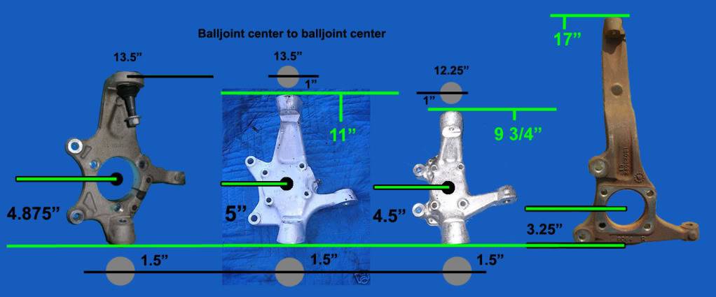
What I found is the height for the '68 Riviera Spindles I have off the car that are interchangable with the ones on the car have a spindle height of 1.875in, way way less than anything in that picture. A C5/6 upright would give me a 3in drop in right height just with the spindles, another 2in to flatten the lower control arms would put me at 5in of drop on my current 8.25in ground clearance. I'm not riding that low!
I take this to mean that I'd have to put the ball joint on top of the lower mount to bring that back into the range of useable to bring the lower control arm level. Playing around with the excell model, I can't get a possitive camber till 3in of extension with the C5/6 spindles mounted conventionally. I'm afraid it looks like there isn't a way to mount any of the spindles I have the measurements on and get a useable ride height out with the 2in body drop in relation to the spindles needed for a flat lower control arm.Central TEXAS Sleeper
Experimental Physicist
'64 Riviera T-type: 4.1L Buick Turbo6, 4L80E, L67 OBDII SEFI swap
ROA# 9790
12-02-2011 #7
Registered User
- Join Date
- Oct 2009
- Location
- New Derry, PA
- Posts
- 1,265
Level lower is a good starting point, but it's not cast in stone... If the C5 solves your other problems, just raise the suspension 2" from level. That long lower arm isn't going to move the tire much, and it will go negative camber faster from ride height than a level arm.
Ray Kaufman - Wyotech Chassis Fab and High Performance Instructor. Words of Wisdom from an old master... at Asylum Custom Interiors website
12-02-2011 #8
Registered User
- Join Date
- Nov 2011
- Location
- College Station, TX
- Posts
- 204
If I understand what you are saying, It's not a bad thing to have the lower arm going uphill from the spindle to the body? That's the situation I'd be in with a trying to optimize the right height and use the C5 upright. With 6in ground clearance, I'd end up with the inner points 2.75in above the ball joints using the C5 upright.
Edit: Ooops, left the 17in F-body upright in the excel model but that might be a better candidate. Playing around with stuff still since at 6in ground clearance, the C5 upright is still too short with the inverted ball joint, assuming 2.5in of height gain for flipping it over things look better.
Anything bad about the 4th Gen F-body upright?Central TEXAS Sleeper
Experimental Physicist
'64 Riviera T-type: 4.1L Buick Turbo6, 4L80E, L67 OBDII SEFI swap
ROA# 9790
12-03-2011 #9
Registered User
- Join Date
- May 2002
- Location
- Northern California
- Posts
- 10,716
...just that the upper arm will be in your fender...very high up. Originally Posted by CTX-SLPR
 MrQuick ΜΟΛ'ΩΝ ΛΑΒ'Ε
12-03-2011 #10
Registered User
- Join Date
- Oct 2009
- Location
- New Derry, PA
- Posts
- 1,265
I'm with Quick on the F-body spindle... Those cars were designed to carry the upper arm load much higher in the chassis. You're getting a long way above the Riv frame with the upper arm mounts, and you'll have to build a support structure for them.
How long of a lower arm are you planning on using? I'm sure you're aware that you can calculate the angle of the lower arm and the side movement of the ball joint for the 2.75" height difference. I'd be interested to see what the camber curve does. Actually sounds about like stock ride height as far as the lower arm is concerned.
Ray Kaufman - Wyotech Chassis Fab and High Performance Instructor. Words of Wisdom from an old master... at Asylum Custom Interiors website
12-03-2011 #11
Registered User
- Join Date
- Nov 2011
- Location
- College Station, TX
- Posts
- 204
The lower arm I've speced out is 18.75in long to put the upright in possition to fit an 18x8in wheel with the same scrub radius as the C5 without affecting the track width since there is not much room for a wide tire upfront. This coresponds to an 11.2in upper arm (centerline to balljoint) to dial in -1.11º of static camber with 1/8in of shims on the A-arms. Factors I use to calculate this include, spindle height, upper control arm length, lower control arm length, pivot point offset between upper and lower in both vertical and horizontal, spindle horizontal offset between ball joints, and the ride height of the ball joint in relation to the control arm pivot point. I then calculate camber based on the difference between the horizontal possisions of the ball joints at different amounts of ball joint vertical movement from ride height. I've not added caster calculations yet.
With an assumed 2in higher upper ball joint position on the C5/6 upright from inverting it I get ~1.06º of camber loss in 1in of compression from ride height. Was thinking machining a top hat style steel insert for the spindle with a heavy washer and retaining clip to use a through bolt style ball joint on the top. Since this is largely a street car, I'd like to stay away from rod end type suspension components. For the brake reaction rod I might have to though since a rubber bushing will allow that link to move all over the place. Just thought about using a ball joint in that location with a tierod type adjuster for changing the length of the rod to affect more or less caster. I would expect camber to be unaffected since the attach point to the frame is at the same height as the LCA mount.Central TEXAS Sleeper
Experimental Physicist
'64 Riviera T-type: 4.1L Buick Turbo6, 4L80E, L67 OBDII SEFI swap
ROA# 9790
12-04-2011 #12
Registered User
- Join Date
- Oct 2009
- Location
- New Derry, PA
- Posts
- 1,265
By camber loss, do you mean camber is going negative (top of tire in)? Originally Posted by CTX-SLPR
As far as using Heims goes, you are pretty limited on choices at the upper ball joint and the strut (brake) rod mount. If you flip the upper ball joint, you lose the taper, so that kind of rules out a ball joint on top without putting some sort of big sleeve in the hole. A ball joint should work for the strut rod mount, but you won't have much "tie rod" adjustment, as the threads aren't very long. Your only other options are Johnny joint (plastic lined but HUGE), rubber (don't want to go there), or Heim...
I've been wondering about a weld in Johnny joint (uniball) mounted sideways, and using the hole where the pivot bolt would normally go to mount the strut rod. It would be pulling axially, though, and I've never read up on the axial load ratings on those.
Ray Kaufman - Wyotech Chassis Fab and High Performance Instructor. Words of Wisdom from an old master... at Asylum Custom Interiors website
12-04-2011 #13
Registered User
- Join Date
- Nov 2011
- Location
- College Station, TX
- Posts
- 204
Yes, the camber gets more negative as the suspension compresses Originally Posted by exwestracer
I actually was thinking big steel insert with something like a 1/4in lip on one side (probably top) with a washer with similar width on the otherside retained by either a nut or a clip in a retaining groove. Since the hole is so large in comparison to the taper and threaded section of the ball joint I could probably get away with a counter bored section for the castle nut to still leave enough height for the washer and it's retension mechanism. I'll draw it up this evening.
Your idea on the Uniball/Johnny joint is exactly what I was thinking with the ball joint since they are designed for loading in compression and tension. Just thread an adjuster like you use on a tierod end between it and the rod attached to the LCA. I agree that the threads wouldn't be very long but with proper engineering the small adjustment should be all that's needed vs. an "adjust to fit".
Tell me more about the '63 Riv you're looking at. I can give you pointers on where to check for trouble and there is some unique stuff to a '63 over the 64 and 65.Central TEXAS Sleeper
Experimental Physicist
'64 Riviera T-type: 4.1L Buick Turbo6, 4L80E, L67 OBDII SEFI swap
ROA# 9790
12-04-2011 #14
Registered User
- Join Date
- Oct 2009
- Location
- New Derry, PA
- Posts
- 1,265
So far, I have one crappy cell phone pic, and no returned messages... I'm just looking at it for a solid body. The chassis and suspension would be a "clean sheet" build.
Ray Kaufman - Wyotech Chassis Fab and High Performance Instructor. Words of Wisdom from an old master... at Asylum Custom Interiors website
12-04-2011 #15
Registered User
- Join Date
- Nov 2011
- Location
- College Station, TX
- Posts
- 204
Check the cross bracing on the floor pans and under the trunk, they tend to collect debris at the ends and rot out. Also check around the rear window and the battery tray for rust. Originally Posted by exwestracer
Central TEXAS Sleeper
Experimental Physicist
'64 Riviera T-type: 4.1L Buick Turbo6, 4L80E, L67 OBDII SEFI swap
ROA# 9790
12-04-2011 #16
Registered User
- Join Date
- Oct 2009
- Location
- New Derry, PA
- Posts
- 1,265
Thanks, I'll be sure to look closely if I ever get that far...
Ray Kaufman - Wyotech Chassis Fab and High Performance Instructor. Words of Wisdom from an old master... at Asylum Custom Interiors website
12-12-2011 #17
Registered User
- Join Date
- Nov 2011
- Location
- College Station, TX
- Posts
- 204
Sorry, been sick and busy. Lurked a bit but time to say stuff again.
Been thinking over the ride height and suspension bits and realized that my current set up is actually riding very high in the suspension due to the lighter V6 in the nose. I'm probably 1in from the bumpstops, granted they are huge 1.5-2in tall rubber bump stops. This means going up by 0.75in would practically put me on the current bumpstops. Now with the dramatically rearranged suspension pieces I won't be close to crashing the upper control arm into the frame since it's angled the other way but it did make me think through this.
The next bit was the design problem of how to mount the front coil overs onto the lower arm. Since the lower arm is a straight piece and probably tubular, how do you mount a coil over that drops down on the center of the tubular arm? Is the best way to put a saddle on top of the arm and just run something short enough to fit in the space? Does the arm need to be sectioned and a 'U'-channel welded in to pick up the lower bolts? I'm probably going to go with air ride Shockwaves on this since I like the ability to raise the ride height to clear objects or steep inclines. I will however be specing them out so that the three different settings end up with a usable track height/inflation combo on the bottom, potentially a compromise inflation for the street ride height, and the top one will be all up.
Thanks for following the ramblings,Central TEXAS Sleeper
Experimental Physicist
'64 Riviera T-type: 4.1L Buick Turbo6, 4L80E, L67 OBDII SEFI swap
ROA# 9790
12-13-2011 #18
Registered User
- Join Date
- Oct 2009
- Location
- New Derry, PA
- Posts
- 1,265
How about a pic of the stock control arm? I usually try to let the part tell me what it wants done to it...
Ray Kaufman - Wyotech Chassis Fab and High Performance Instructor. Words of Wisdom from an old master... at Asylum Custom Interiors website
12-13-2011 #19
Registered User
- Join Date
- Nov 2011
- Location
- College Station, TX
- Posts
- 204
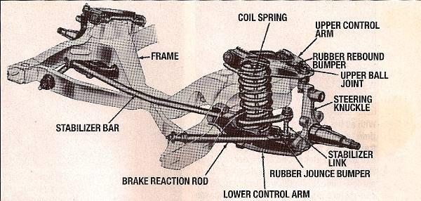
here's the shop manual diagram for the front suspension:
Here's about the best thread I can find with pictures of the suspension: http://www.jalopyjournal.com/forum/s...=riviera+start
Remember I'm going to be making these arms more than a few inches longer to push the kingpin axis out to match C5 scrub radius specs.Central TEXAS Sleeper
Experimental Physicist
'64 Riviera T-type: 4.1L Buick Turbo6, 4L80E, L67 OBDII SEFI swap
ROA# 9790
12-13-2011 #20
Registered User
- Join Date
- Oct 2009
- Location
- New Derry, PA
- Posts
- 1,265
CTX,
I tried to import a couple of those pics form the HAMB link, but they wouldn't work. Seeing as how the outer end is already boxed, I'd give some thought to making a bracket to use the existing brake reaction rod bolts to mount the bottom of the coilover, possibly adding a 3rd bolt further out through one of the "ears", as those 2 are placed. That will move the spring path out closer to the ball joint, and would allow you more shock travel and to run a softer spring rate than if the shock were closer in.
Ray Kaufman - Wyotech Chassis Fab and High Performance Instructor. Words of Wisdom from an old master... at Asylum Custom Interiors website

 Reply With Quote


