


Results 1 to 12 of 12
Thread: Engine/Trans angle?
-
05-26-2011 #1

 Registered User
- Join Date
- Oct 2006
- Location
- McKinney, TX
- Posts
- 899

Engine/Trans angle?
I have been trying to find an answer on this, but there isn't really a whole lot of info (that I have found) on lining up the driveline at the correct angle. I have found tons of info on Pinion Angle, but not so much on Trans/Engine angle...
Here is the best summary I have read about Pinion Angle:
Ladder-Bar Suspension 1/2 degree of pinion angle
4-link 1-2.5 degrees of pinion angle
leafs 6-7 degrees of pinion angle
So, that brings me back to the transmission. If I am fabbing my own transmount, What angle do I want the engine/Trans to aim?
The pic below is an exaggerated image to help illustrate my point. It is entirely possible that it is not important, so long as the pinion angle is set according to the specs above...but I would like to know what the suspension pros have to say about it before I go fabbing up my crossmember!
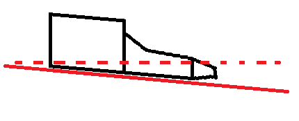
And if there is some importance to setting the angle, where do I take the measurement from?
Thanks!
Confucius says, "Choose a job you love, and you will never have to work a day in your life"
My build Beast
-
05-26-2011 #2 Registered User
- Join Date
- Jul 2006
- Location
- Pensacola, FL
- Posts
- 1,265
I have been thru this many times in the last year. I still have not grasped it totally. The consensus seems to be- if the driveline is down X degrees, the pinion should be up X degrees. Basically if you were to draw a line thru the pinion angle & the driveline agle, they should be parallel. There should be some angle (either + or -) or the U joint will have a slight bind. Most research I have done suggests 2.5-3 degrees down on the trans is about as much angle that you should have. Lastly, the driveshaft should not slope upward from the trans to the rear end. I am no expert, as I am still working on my setup. Seems everyone has a different view on the subject. I'm sure other with more experience than I will chime in. Scott

05-26-2011 #3
Registered User
- Join Date
- Feb 2010
- Location
- Corvallis Montana
- Posts
- 597
I'm at the same step in my build i need to make my trans mount for my 1969 camaro i have a l92 with a 6l80e and i cant find a mount anywhere so it looks like i will be fibbing it up so if anyone else can help with the angle of the rear tail shaft it would help out!!! good thread!
05-26-2011 #4
 Registered User
- Join Date
- Sep 2010
- Location
- Beach Park IL
- Posts
- 3,048
The angles should be parallel as already stated, sometimes I setup pinion angle slightly down from parallel, it depends on the suspension.
The 3 degree "standard" driveline angle comes from most carb intake being manufactured with 3 degrees built in. So with a 3 degree angle (tailshaft down) the carb ends up level. With fuel injection it's not as
big a deal, put it where it fits best and adjust pinion to match...that's how I do it anyways, your mileage may vary...
05-27-2011 #5
Registered User
- Join Date
- Oct 2006
- Location
- McKinney, TX
- Posts
- 899
Been looking around online and found this pic that seems to illustrate the parrallel that has been mentioned:

So, could I use an empty slip yoke in the tail of the trans and a magnetic angle finder to figure this out?Confucius says, "Choose a job you love, and you will never have to work a day in your life"
My build Beast
05-27-2011 #6
Registered User
- Join Date
- Sep 2010
- Location
- Beach Park IL
- Posts
- 3,048
You don't even need the trans yoke. Square against the tailshaft would work, we have used the engine oil rail, too. They are parallel to the crank centerline. That picture is cool, worth a thousand words
05-27-2011 #7 Registered User
- Join Date
- Nov 2002
- Location
- state of confusion
- Posts
- 1,499
Just that perfectly in line is not a perfect situation. You need a tiny bit of angle at each joint so that the needle bearings in the cups will actually roll around a little.
http://www.dennysdriveshaft.com/freq...questions.htmlHow much driveline angle is right for my application?
Thats a loaded question. The best answer is....the least amount of driveline or u-joint angle is the best amount of angle. Try to achieve the least amount of u-joint angle but don't make it less than 1 degree. A little known fact about u-joints is that they require about 1 degree of operating angle to get the needle bearings rotating. If they do not rotate they will fail.
Norm'08 GT coupe, 5M, suspension unstockish (the occasional track toy)
'19 WRX, Turbo-H4/6M (the family sedan . . . seriously)
Gone but not forgotten dep't:
'01 Maxima 20AE 5M, '10 LGT 6M, '95 626, V6/5M; '79 Malibu, V8/4M-5M; '87 Maxima, V6/5M; '72 Pinto, I4/4M; '64 Dodge V8/3A
05-27-2011 #8 Registered User
- Join Date
- Aug 2004
- Location
- Rustburg, Virginia
- Posts
- 3,436
I found this a while back...
Stole these pics off someone's site...don't remember where though.
1970 RS/SS350 139K on the clock:
89 TPI motor w/ 1pc rear seal coupled to a Viper T56 via Mcleod's modular bellhousing w/ hydraulic T/O bearing from the Viper, 12 bolt rear w/ 3.73 gearing, SC&C upper control arms, factory lowers with Delalums, C5 brakes at all four corners, Front Wheels 17x8's with Sumi 255/40/17 and Rear Wheels 17x9's with Sumi 275/40/17.
Brief description of the work done so far can be found here: http://www.nastyz28.com/forum/showthread.php?t=112454
05-31-2012 #9
New to Pro-Touring
- Join Date
- Dec 2011
- Posts
- 5
How about starting at the engine. Put a level on the intake where the carb bolts to and make sure it's level.. Use an angle finder on the oil pan rail, starter pad, or back of crankshaft. Once you bolt the transmission to the engine it should be the same angle. Fab a mount to hold this angle. Set the pinion angle up the same angle as the engine & transmission downward angle.
06-01-2012 #10 Registered User
- Join Date
- Oct 2009
- Location
- New Derry, PA
- Posts
- 1,265
The real key to all of this is that the yokes are parallel (or in line) UNDER LOAD. That is why you will see different pinion angles recommended for different suspensions. Each design allows a certain amount of "pinion climb", with leaf springs being the highest. Most OEM or "street" oil pans, trans pans, and carb intakes are designed to work at 2-3deg down angle to the rear. Do NOT set up a pinion (at rest) pointing UP to match this angle on anything other than a torque arm or truck arm suspension. Originally Posted by absintheisfun

Some of the pinion angles listed above come from the racing world, and assume the engine is mounted level in the chassis. Note that many racing oil pans and manifolds are parallel to crank centerline. If you are running EFI and a custom oil pan, I would recommend lowering the engine in the chassis as much as practical (until level), and setting up the pinion angle accordingly.
Ray Kaufman - Wyotech Chassis Fab and High Performance Instructor. Words of Wisdom from an old master... at Asylum Custom Interiors website
08-14-2012 #11
Registered User
- Join Date
- Aug 2012
- Posts
- 11
I can't comment on your settup, or why you want your tailshaft to sit at that angle. But all manufacuters from the factory have the driveshaft slightly angled to the passenger side, in other words the rearend is offset to the passenger side and the driveshaft sits at an angle sideways, not alot, but just alittle. They do this so the needle bearings in the u-joints will spin and cool the u-joint to keep the u-joints from failure because of heat. If the driveshaft is at an extreme angle, all types of problems will occur sooner or later. At an angle like that you're practically spinnig the u-joints like a hoola hoop.
08-15-2012 #12
Registered User
- Join Date
- Jul 2009
- Location
- New Jersey
- Posts
- 536
Well, just be glad you aint me. I'm sorta stuck with the "best I can get" in my build. The 4 link and my floor leaves little room to put the pinion anywhere other then where its at. Luckily its all pretty close. I guess the point of my post is to set the car up at ride height and see where you are in the back while you figure out the front. There was a dramatic difference between "normal" stance and "full kill" stance that I was not expecting. (At least in my 1st gen). Like most of us, I drive around in full kill so that had to be accounted for. Had I set the motor up first, then tried to compensate with the 4 link I would have run out of real estate.
RJ Cilurso
67 Camaro with a few things bolted to it
12 Camaro with a few things bolted to it
50 Chevy 5 window p/u with a few things unbolted
USAF

 Reply With Quote


