


Results 21 to 40 of 45
Thread: Help me understand...
-
01-05-2011 #21

 Registered User
- Join Date
- Oct 2009
- Location
- New Derry, PA
- Posts
- 1,265
 About the only way to slow the progression is to lengthen the UCA (which you said you can't do). Raising the UCA mount will slow the gain from start to finish, but you may not have enough gain at first.
 Originally Posted by wellis77

If both arms are canted down toward the front (side view), and the upper is tilted more than the lower, then your IC for anti-dive is outside the wheelbase (ahead of the car), no? The anti-dive may work that way because the vehicle weight doesn't have the same leverage over the front suspension with the fulcrum that far ahead of the C/G. Interesting idea, and one I'm not familiar with. With the UCA at a higher angle, you should be losing (slight) caster on bump (and under braking), as Ben pointed out. Your simulation results don't show that, so something isn't making sense there...
Ray Kaufman - Wyotech Chassis Fab and High Performance Instructor. Words of Wisdom from an old master... at Asylum Custom Interiors website
-
01-05-2011 #22
 Registered User
- Join Date
- Nov 2005
- Location
- Auburn, WA
- Posts
- 1,360
Will, I've been playing with the Viper front in WinGEO and I gotta admit it doesn't look too bad with a short UCA. The only thing that I see is a fairly bad RC migration during cornering and bump/rebound. The RC vertical change is double of what it should be (should move in a 1:1 ratio), and the lateral movement is actually going in the wrong direction and at about 4 times the rate of what I'd like to see. If you limit your overall travel you can mitigate these effects, but that takes the fun out of driving the car.
Can you shorten the LCA proportionally? If you want, send me the XYZ specs you are using so we're speaking on the same page.Matt Jones
Mechanical Engineer
Art Morrison Enterprises
-
01-05-2011 #23
 Registered User
- Join Date
- Jul 2009
- Location
- Grand Rapids, MI
- Posts
- 1,559
Hey Matt, thanks for dropping in. On account of I have jet lag, I've been laying thinking "since I shortened the UCA 1.5", why not build a set of custom LCA's that are identical, but 1.5" shorter". So yes, I can shorten the LCA.
I'll PM you the XYZ specs shortly. Thanks.
-
01-06-2011 #24
 Registered User
- Join Date
- May 2002
- Location
- Northern California
- Posts
- 10,716
I think you did the same thing I did when I ran the numbers through PT. Where are you gettting the control arm pivot height measurments from? As in position. You are on the right track with the shorter arms. Keep your ratios the same.
The measurments did not jive and it wasn't till I mapped it out on paper at full scale did I understand what was going on. The imporant thing here is IC, RC location and migration.
My PT version died and will not run onmy new computer.
VinceMrQuick ΜΟΛ'ΩΝ ΛΑΒ'Ε
-
01-06-2011 #25
Registered User
- Join Date
- Jul 2009
- Location
- Grand Rapids, MI
- Posts
- 1,559
I may have to map it on paper as well, but the pivot locations are measured from the ground. I hope I understood your question right. If so, I thought that's what the PT Y measurement comes from, the ground. X is from vehicle centerline, Z is from the spindle/axle centerline. Let me know if I misunderstood your question.
-
01-06-2011 #26
Registered User
- Join Date
- May 2002
- Location
- Northern California
- Posts
- 10,716
Hey Will, but at what location was your Y measured from? From the ground to what point at pivot on the control arms. It will be clear once you think about it. An inch can make a huge difference. That is where the analyser gave me problems.
VinceMrQuick ΜΟΛ'ΩΝ ΛΑΒ'Ε
01-06-2011 #27
Registered User
- Join Date
- Jul 2009
- Location
- Grand Rapids, MI
- Posts
- 1,559
I went to the pivot center for all locations, be it X, Y or Z. This is particularly difficult for the ball joints. Where should the measurement be made to at the pivots?
01-07-2011 #28
Registered User
- Join Date
- Jul 2009
- Location
- Grand Rapids, MI
- Posts
- 1,559
So after chatting with Vince (Mr.Quick) for a bit I realized one problem with the measurements I took which led me to finding a second problem with my UCA pivot inputs. First I wasn't measuring the height at the center of the pivot. I measured height at the front of the front bushing and the rear of the rear bushing (for both upper and lower control arms). What this means is the LCA vertical measurements are off 3/32" to 1/8" (too low for the front and too high for the rear) and the UCA vertical measurements are off 1/16" (too low in the front and too high in the rear). The more dramatic is the fore/aft of the UCA is WAY off. Now that I'm back in Switzerland I only have the incorrect UCA measurements, but it looks as though the front UCA should be in the range of -2.5" to -3.5" and the rear UCA should be in the range of 6.5" to 5.5". What I put into the software was -5.1 front and 4.6 rear. I have a feeling these two changes will have a dramatic impact on the results, especially the fore/aft of the UCA. I will still probably have to shorten the LCA by @ 16.7% (proportional to the UCA change) but these alone will likely have a big impact.
I have to figure out what I want to do for software so I can get these updates plugged in. Since I shortened my UCA I don't think I can fit the standard Viper air springs between them so I may have to go with something with a shorter stroke. In talking with Britt from Ride Tech, in order to not notice a difference in ride quality I need to keep my suspension travel at 5 inches. Based on my motion ratio, if I need to go to a shorter stroke shock, I'll have to move the control arm shock mount in about 3/4".
I sure am glad there are a lot of smart people here to help me get this all worked out. Thanks everybody, you have now idea how much I appreciate the help.
01-07-2011 #29
Registered User
- Join Date
- Jul 2009
- Location
- Grand Rapids, MI
- Posts
- 1,559
I mapped this out Ray with the UCA pivots at -2 9/16" and 5 7/16 (rough estimate) and the IC for anti-dive is behind the car at 20' 1 7/8" with the height 2' 5 15/16" above ground. Originally Posted by exwestracer
01-07-2011 #30 Registered User
- Join Date
- Nov 2008
- Location
- TN
- Posts
- 954
I was thinking those numbers looked really strange.
Benjamin
Twin Dusters
'72 Plymouth Duster "Aero Duster" project
'72 Plymouth Duster "Daily Duster" project
https://www.pro-touring.com/showthre...RO-DUSTER-quot
01-07-2011 #31
Registered User
- Join Date
- Oct 2009
- Location
- New Derry, PA
- Posts
- 1,265
Ok, I was just going off the tilt values you had given in post #16. If they are both tilted down (forward), and the top more than the bottom, they HAVE to converge at the front. Originally Posted by wellis77
The values on your original chart:
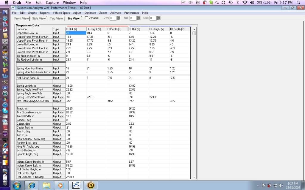
back up what you stated above. The LCA seems to be tilted more, so your IC would be to the rear.
Ray Kaufman - Wyotech Chassis Fab and High Performance Instructor. Words of Wisdom from an old master... at Asylum Custom Interiors website
01-07-2011 #32
Registered User
- Join Date
- Jul 2009
- Location
- Grand Rapids, MI
- Posts
- 1,559
Yeah, the LCA is tilted just a bit more than the UCA. What would the impact be if I were to rotate the control arms down so the LCA is level? The IC length would remain the same but the the height would be 7 1/4". Would that have an effect on handling at all?
01-07-2011 #33
Registered User
- Join Date
- May 2002
- Location
- Northern California
- Posts
- 10,716
What I would do is find your IC relation to center of gravity and try to stay around that intersect. We are still taking front suspension correct? Find your CG, IC's and don't forget your roll centers.
If anything I would recommend doing a rough plot out and adjust from there.
Remember the Vipers had no ABS or track control so relations I would assume determined anti dive and anti squat locations.MrQuick ΜΟΛ'ΩΝ ΛΑΒ'Ε
01-07-2011 #34
Registered User
- Join Date
- Jul 2009
- Location
- Grand Rapids, MI
- Posts
- 1,559
Yeah definitely still talking front suspension. CG is going to be tough since I can't way the car at all, best I can do is take a rough guess. I heard a super general rule once that said you can use the cam shaft as an estimate? If that is a decent starting point, I'm close already but I do need to take a closer look at roll centers. I need to read up on them a bit more as well to make sure I fully understand them, there effects on handling, and how they change.
01-07-2011 #35 Registered User
- Join Date
- Oct 2009
- Location
- San Diego, CA
- Posts
- 226
How so? Originally Posted by silver69camaro
--Jason Rhoades
http://www.rhoadescamaro.com/build
01-07-2011 #36
Registered User
- Join Date
- Oct 2009
- Location
- New Derry, PA
- Posts
- 1,265
Your side view IC mainly has an effect under braking and caster change in bump and droop. With the limited travel you have available, rotating them shouldn't have a huge effect on overall handling. Leveling the LCA will make the suspension more compliant over bumps (better ride quality). Originally Posted by wellis77
Keep in mind that those stock control arm angles may likely have had as much to do with packaging as optimal geometry...
Ray Kaufman - Wyotech Chassis Fab and High Performance Instructor. Words of Wisdom from an old master... at Asylum Custom Interiors website
01-07-2011 #37
Registered User
- Join Date
- Nov 2008
- Location
- TN
- Posts
- 954
Actually, as serious as Dodge was when they re-did the viper, I highly doubt that they would have compromised geometry for packaging. since their goals included setting record laps all around the world with the car. Originally Posted by exwestracer
Benjamin
Twin Dusters
'72 Plymouth Duster "Aero Duster" project
'72 Plymouth Duster "Daily Duster" project
https://www.pro-touring.com/showthre...RO-DUSTER-quot
01-07-2011 #38
Registered User
- Join Date
- May 2002
- Location
- Northern California
- Posts
- 10,716
and they did, many times over but i agree, there is alot of room for everything else. Looks like they optimized the suspension then designed everything around it....after plopping the V10 dead front center that is.
VinceMrQuick ΜΟΛ'ΩΝ ΛΑΒ'Ε
01-08-2011 #39
Registered User
- Join Date
- Aug 2004
- Location
- England
- Posts
- 1,042
What about the McPherson strut option,I have posted a bit more on the project update page by mistake,doh!!!
01-08-2011 #40
Registered User
- Join Date
- Nov 2008
- Location
- TN
- Posts
- 954
dead middle center is more like it.. the whole thing and all the accessorys are behind the front wheel centerline. Originally Posted by MrQuick
Benjamin
Twin Dusters
'72 Plymouth Duster "Aero Duster" project
'72 Plymouth Duster "Daily Duster" project
https://www.pro-touring.com/showthre...RO-DUSTER-quot

 Reply With Quote


