

Results 1 to 16 of 16
-
08-14-2010 #1
 Registered User
- Join Date
- Nov 2006
- Posts
- 867

Hydroboost Installation w/ pics......
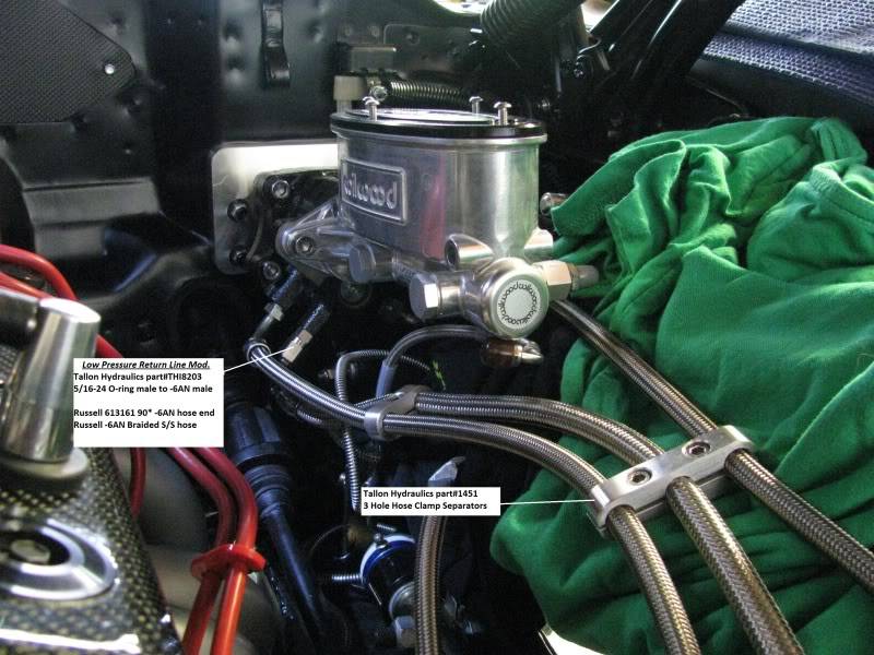
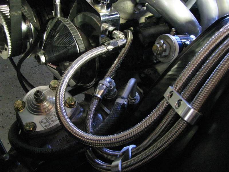
I started with the Hydratech Hydroboost kit which came complete with everything needed for the basic installation. After reading many many threads about this install, I discovered a modification which runs the low pressure return line direct to the Power Steering Pump. This eliminates a "T" fitting in the basic kit and prevents any fluid feedback to the HB unit.
Parts for that mod were Tallon Hydraulics part# 8203 (5/16-24 O-ring male to -6AN male), 2-Russell 613161 90* -6AN hose ends, Russell 670850 -6AN Fuel Cell Bulkhead fitting, Tallon Hydraulics part# 1451 2pack of 3 Hole Hose Clamp Separators and Russell Stainless Steel braided low pressure hose.

First drain the PS pump reservoir, remove old PS hoses from pump and steering box
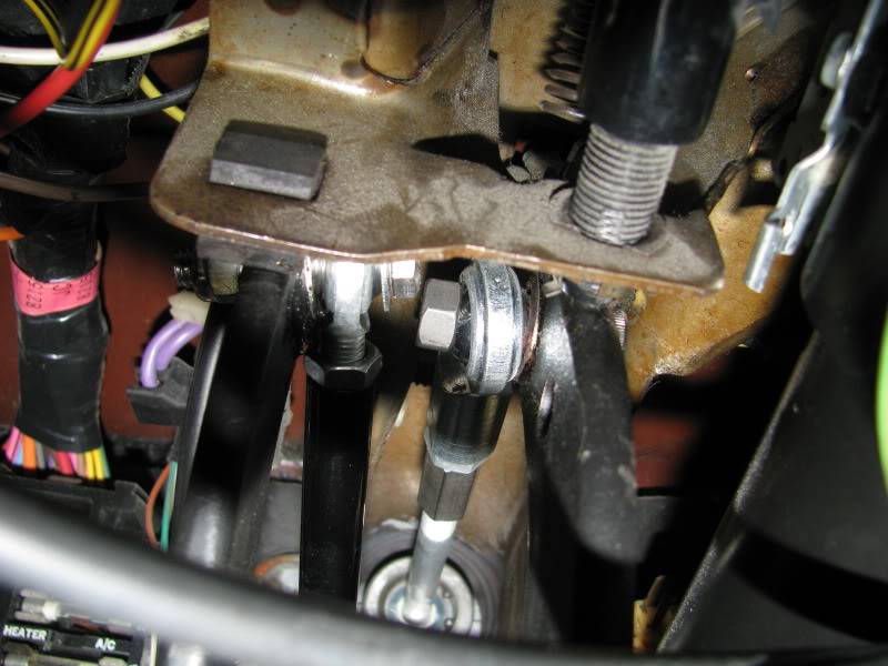
Then remove old master cylinder brake pedal rod from the brake pedal
Disconnect the front and rear brake lines and remove the old master cylinder
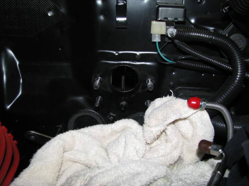
I made a new gasket to fit between the new HB unit and the firewall, I used Felpro# 3157 rubber fiber gasket material from NAPA Auto Parts.
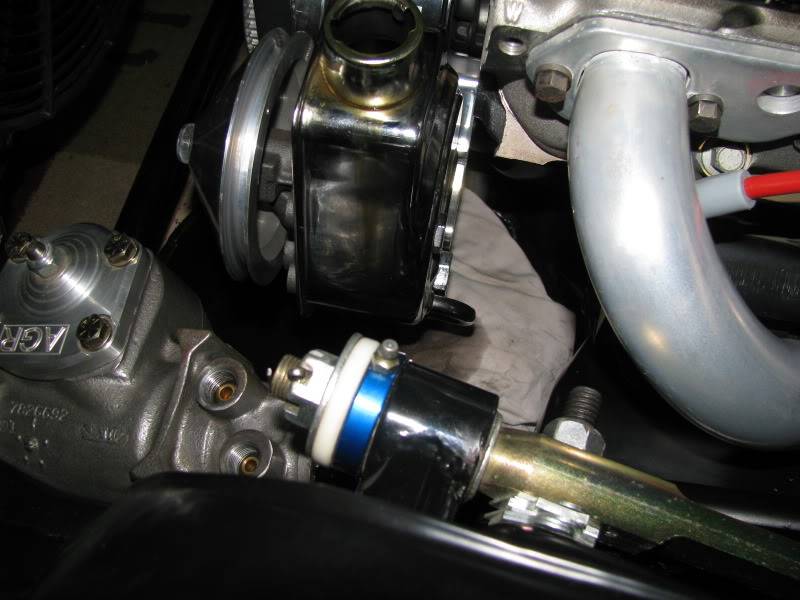
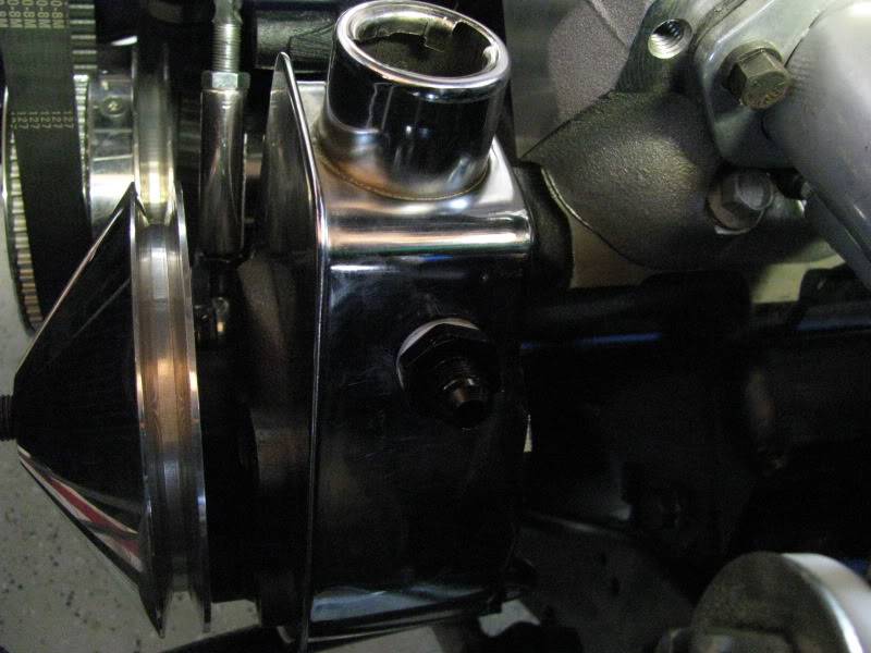
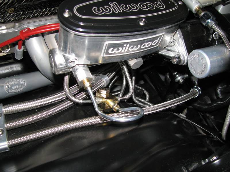
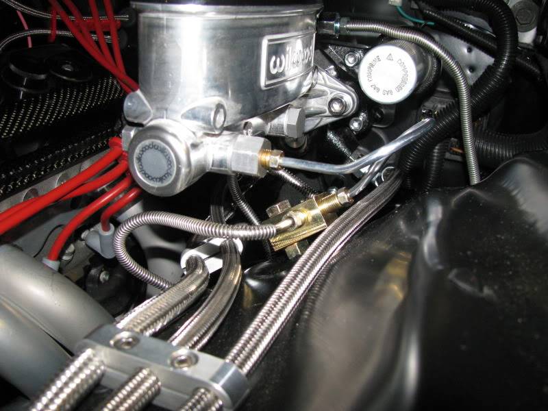
Then I installed the HB unit. Before installing the Wilwood master cylinder, install the two high pressure lines and the low pressure return line. Installation of these hoses is nearly impossible if you install the master cylinder first (ask me how I know). Remove the preinstalled brass 90* fitting for the low pressure return port from the HB unit, and replace with the THI 5/16"-24 O-ring male to -6AN male fitting on the HB unit. Be sure to torque ONLY to 10 ft. lbs. as the threads for this fitting can strip very easily. Use one wrench to hold this fitting while tightening the Russell part# 613161 90* hose end with another wrench.
Day 2) I drilled a hole above the fluid line in the PS pump reservoir and installed the Russell #670850 -6AN Fuel Cell bulkhead fitting in the reservoir for the low pressure return line from the HB unit. I stuffed a clean shop rag into the reservoir, spread some grease on the end of the drill bit(metal particles stick to it), and vacuumed real well with the shop vac to make sure no metal particles got into the reservoir.
Then I cut to proper length, the two high pressure lines coming from the HB unit and installed the Aeroquip fittings and then installed them in their proper locations, and also installed the Russell part# 613161 90* hose end on the other end of the low pressure return line and installed that on the PS reservoir.
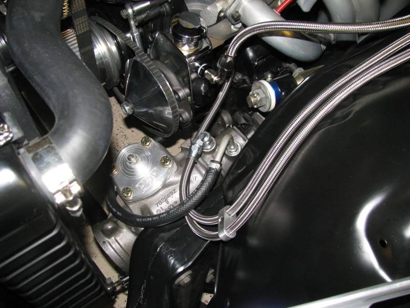
Next I need to fill the power steering pump with fluid, and bleed the system, checking for any possible leaks. I'll be securing the two hose clamp separators to the inner fender, I need some new hardware for that. I also need to bend some new lines for installation of a proportioning valve and then bleed the brakes. Then a test drive!!
-
08-14-2010 #2 Registered User
- Join Date
- Oct 2005
- Location
- Finksburg, MD
- Posts
- 22
Great write up so far Scott! Great looking set-up!
 George Morris
08-18-2010 #3
Registered User
- Join Date
- Sep 2007
- Location
- Denver
- Posts
- 325
Thanks for the thread on this. I was just trying to figure out how to hook up -6 an line to the return. The factory return fitting hit my header with no line attached......don't ask how I know after slipping the subframe up under the body and bolting it up .After asking around no one had ideas on an adapter...until now. Helps me a bit...I'll look up to see where I can find that adapter.
 David Beckstrom DVM
08-18-2010 #4
Registered User
- Join Date
- Sep 2007
- Location
- Denver
- Posts
- 325
Got a question....how did you hook up return line from steering unit? Looks like your pump like mine comes with a 3/8" slip fitting for a hose and clamp. Mine is plastic but sort of permanently attached so no way to convert to any kind of screw attachment setup.
David Beckstrom DVM
08-18-2010 #5
Registered User
- Join Date
- Nov 2006
- Posts
- 867
I have not been able to convert that return line from the steering box to a Stainless braided line yet. That return line as you see it is a completely stock line.....it's the black rubber line on the steering box.
08-18-2010 #6
Registered User
- Join Date
- Apr 2005
- Location
- Vail, Arizona
- Posts
- 660
That looks great! I love the return line idea. Wish I would have done something like that! Future mod!
08-19-2010 #7 Registered User
- Join Date
- Jan 2006
- Location
- Dallas, Ga.
- Posts
- 439
Looking good Scottie! You're going to enjoy the effect that unit has on your brakes. Nice clean installation on the return line from the HB.
Tommy Parker
1973 Camaro- fast burn 385, FAST EFI, Bowler 700R4, Hotchkis,Baer, Forgeline SP3P's, completed 2007, updated 2010
1972 Camaro-Project Fool's Gold- LD 3-link,DSE sub-frame,C6 Z06 brakes,TKO 600, LS2 stroked to 402, Forgeline, in progress
08-19-2010 #8 Registered User
- Join Date
- Aug 2004
- Location
- Rustburg, Virginia
- Posts
- 3,436
Nice write up and pics Scottie!..<insert Thumbs Up smilie>
1970 RS/SS350 139K on the clock:
89 TPI motor w/ 1pc rear seal coupled to a Viper T56 via Mcleod's modular bellhousing w/ hydraulic T/O bearing from the Viper, 12 bolt rear w/ 3.73 gearing, SC&C upper control arms, factory lowers with Delalums, C5 brakes at all four corners, Front Wheels 17x8's with Sumi 255/40/17 and Rear Wheels 17x9's with Sumi 275/40/17.
Brief description of the work done so far can be found here: http://www.nastyz28.com/forum/showthread.php?t=112454
08-19-2010 #9
Registered User
- Join Date
- Jul 2006
- Posts
- 294
First of all, excellent write up and work. Thanks for the pics and explanation.
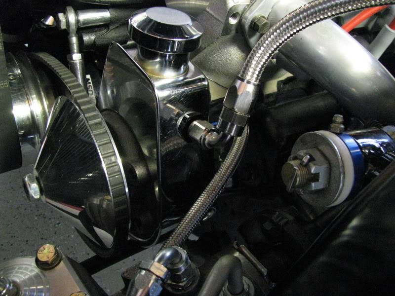
I am not being critical but is there a reason for using a 90* fitting out of the PS pump? My first thought was a straight fitting would allow the hose to go over to the other hoses and keep the line away from the header heat.
Great job thanks for taking the time to post.
Tom
08-20-2010 #10
Registered User
- Join Date
- Jan 2006
- Location
- Dallas, Ga.
- Posts
- 439
Yes Scott, do be weary of the heat coming from the headers. It can lead to overheating the fluid and burning up a pump. Don't ask me how I know this.
It's also a good idea to use a power steering cooler. Don't use one listed as a ps cooler though, they are too low of a flow rate and will cause a bottle neck when running on a track. I used a small plate fin type transmission cooler for my PS and it flows plenty and works great.
If street use only and no track days or auto-x you can get by without a cooler, but get the line away from the header tube.Tommy Parker
1973 Camaro- fast burn 385, FAST EFI, Bowler 700R4, Hotchkis,Baer, Forgeline SP3P's, completed 2007, updated 2010
1972 Camaro-Project Fool's Gold- LD 3-link,DSE sub-frame,C6 Z06 brakes,TKO 600, LS2 stroked to 402, Forgeline, in progress
08-20-2010 #11
Registered User
- Join Date
- Aug 2004
- Location
- Rustburg, Virginia
- Posts
- 3,436
He could turn that fitting a little more toward the front of the car(if the hose is long enough).
1970 RS/SS350 139K on the clock:
89 TPI motor w/ 1pc rear seal coupled to a Viper T56 via Mcleod's modular bellhousing w/ hydraulic T/O bearing from the Viper, 12 bolt rear w/ 3.73 gearing, SC&C upper control arms, factory lowers with Delalums, C5 brakes at all four corners, Front Wheels 17x8's with Sumi 255/40/17 and Rear Wheels 17x9's with Sumi 275/40/17.
Brief description of the work done so far can be found here: http://www.nastyz28.com/forum/showthread.php?t=112454
09-11-2010 #12
Registered User
- Join Date
- Nov 2006
- Posts
- 867
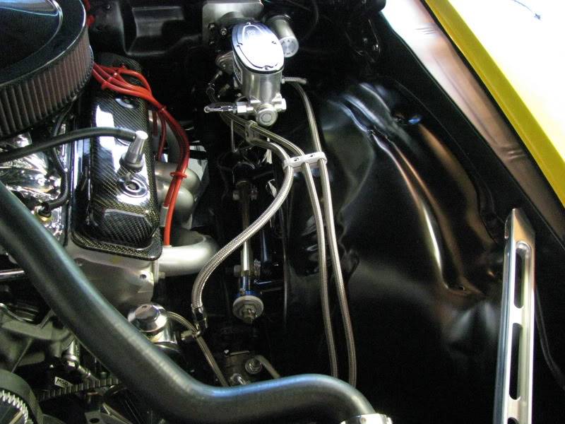
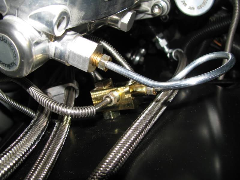
Finally finished the brake plumbing. had to make up some new lines for the different configuration with the Hydroboost setup. Added a new hard line from the "B" port on the Wilwood master, back to the new proportioning valve for the rear brakes. I decided to move the "Tee" fitting for the front brakes up to the inner fender. That required a new hard line from the "A" port to the "Tee".
I also made up a different low pressure return line from the Hydroboost back to the power steering pump reservoir. I made it longer to run it more forward away from the heat of the #1 cylinder header tube.

09-13-2010 #13
Registered User
- Join Date
- Aug 2004
- Location
- Rustburg, Virginia
- Posts
- 3,436
Nice pics Scottie!
1970 RS/SS350 139K on the clock:
89 TPI motor w/ 1pc rear seal coupled to a Viper T56 via Mcleod's modular bellhousing w/ hydraulic T/O bearing from the Viper, 12 bolt rear w/ 3.73 gearing, SC&C upper control arms, factory lowers with Delalums, C5 brakes at all four corners, Front Wheels 17x8's with Sumi 255/40/17 and Rear Wheels 17x9's with Sumi 275/40/17.
Brief description of the work done so far can be found here: http://www.nastyz28.com/forum/showthread.php?t=112454
09-16-2010 #14 Registered User
- Join Date
- Dec 2004
- Location
- NYC
- Posts
- 553
On GM A-body cars there are 2 holes in the brake pedal to connect the brake push rod,one was for manual brake cars and the other was for power brake cars,do you guys know when switching from a manual brake car to a Hydroboost unit if you have to switch it to the hole for power brakes?
ThanksGeorge
`67 Buick GS 400 Hdtp,494ci Stage 2 BBB,5-speed TKO-600,"The Black Widow"
09-17-2010 #15
Registered User
- Join Date
- Nov 2006
- Posts
- 867
It would be placed in the upper (manual brakes) connection point in the pedal. Originally Posted by staged67gspwr

Per Paul @ Hydratech:
NOTE: This system is designed to connect to the brake pedal in the uppermost of the two pedal rod connection points usually found on most pedals. This connection point is approximately one inch higher on the brake pedal than the power brake pedal rod connection point. This upper hole is commonly referred to as the manual brake setting hole. If this hole does not exist on your brake pedal, you will have to remove the brake pedal and drill a new 3/8 hole in the brake pedal. In some cases, this mounting point is occupied by a bolt and a sheet metal tab. Rod angle between the brake assist unit and the brake pedal should be as straight as possible. Brake pedal rod angles exceeding more than 3 degrees off center may eventually fatigue the brake pedal rod causing failure of the linkages, and excessive wear to the assist unit due to side loading the input piston.
09-17-2010 #16
Registered User
- Join Date
- Dec 2004
- Location
- NYC
- Posts
- 553
cool thanks man. Originally Posted by protour73
 George
`67 Buick GS 400 Hdtp,494ci Stage 2 BBB,5-speed TKO-600,"The Black Widow"

 Reply With Quote


