


Results 1 to 20 of 31
Thread: Separating ride from roll...?
-
05-29-2010 #1

 Registered User
- Join Date
- Oct 2009
- Location
- New Derry, PA
- Posts
- 1,265

Separating ride from roll...?
I've been keeping this idea under my hat for a couple of years now, but things change; and most of my fellow competitors don't follow this site...so here's something to ponder, and give feedback on. We've all (well, a lot of us anyway) spent a lot of money on sway bars and trick digressive shocks which try to control roll forces differently than ride (bump) forces. I think there may be a better way, at least for solid axle systems.
I've been intrigued by the Mumford lateral locating linkage ever since I learned about it; and having followed F1 suspension design through the 80s, I noticed the similarity to a "pull-rod" inboard suspension design.
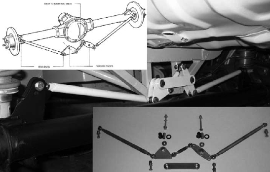
One of the benefits of the Mumford design is the free rotation of the axle about the roll center (the linkage only operates in bump and droop). So what if...the mumford linkage was used to operate a monoshock coilover to hold the weight of the vehicle? The spring and shock would operate in bump, but offer NO resistance to roll forces.
So what to do about roll force? If we consider the physics of roll, what we have is a torque force applied by the vehicle center of gravity about the roll center. Torque is expressed as lb-ft., or pounds of force with a 1ft lever arm. So, if a spring and shock are placed 12" above the roll center to resist roll torque, the units cancel out and what is left is straight pounds of side force. Mount the coilover horizontally, and it has very little, if any, effect on bump movement. So what comes of this is a way to control roll force and damping totally separately form bump force. No more sway bars and 4 way adjustable shocks unless we want them.

Ray Kaufman - Wyotech Chassis Fab and High Performance Instructor. Words of Wisdom from an old master... at Asylum Custom Interiors website
-
05-30-2010 #2
Registered User
- Join Date
- Dec 2009
- Posts
- 261

Cool idea, but I can't imagine what you'd use it for without serious downforce. After all, we typically need more roll force resistance in the form of ARBs, which points to our spring rate being compliantly low as is, just high enough to constrain pitching forces.
So I can't see dropping center spring rate unless we add a lot of anti geometry to control pitch and heave, which isn't really the best addition to be making (though not always a deal breaker.).
But you could do that with a normal system, and the lower the spring rate, the less impact it has on roll anyways.
The mumford link arrangement is a cool idea, though you could just mount the spring on the back of the axle at center and get the same effect, the packaging of both axle locator and center spring arrangement is a cool idea. more compact than trying to package a watts or a panhard even further back from the pumpkin.
And I can't really see the purpose of lateral springs versus two weaker than the center spring in the typical location. Springs can't work until there is motion and since the axle is located through the linkages you'll still operate those springs in single wheel bump( the vehicle still experiences "roll in relation to the axle"), which is a good thing as otherwise single wheel motion would be undamped.
-
06-01-2010 #3
Registered User
- Join Date
- Oct 2009
- Location
- New Derry, PA
- Posts
- 1,265
While it's true the Mumford design offers a VERY low roll center (if desired), the point isn't to allow the chassis more freedom to roll. The lower roll center causes less inside wheel jacking effect, no matter what the level of roll resistance. With a typical spring/shock system however, the rates needed to control roll with a very low R/C are much too stiff in bump, so we run softer springs and add a bar to keep the chassis upright under roll forces. The bar works the same way no matter what type of suspension it's used on; it controls chassis roll by forcing both sides of the suspension to try to do the same thing, in essence converting any setup into a swing arm. The lower the roll center, the stiffer the bar needed to keep the chassis upright, so the more inside jacking we get and the more compliance we give up. The standard solution is to keep raising the rear roll center to keep the car upright without stiff springs or a giant bar. With a sold axle suspension, we always end up in roughly the same place, no matter what route we take to get there...
The purpose of the modifications is to separate control of roll forces and bump forces as completely as possible. Any system with (typical) outboard vertical springs/shocks requires that the spring and shock act as both bump resistance and roll resistance, therefore we are always going to have a compromise in spring and shock selection between what is needed for bump forces and what is needed for roll forces.
Now, there is obviously shock technology out there which allows pretty good results, and as mentioned we can artificially move the roll center with bars; but we are sacrificing traction and bump compliance in doing so.
The idea behind the horizontal coilover for roll control is that it has little or no effect in true bump. The ride coilover can therefore be tuned to resist bump and pitch forces, without affecting roll resistance. In true roll however(lateral g on smooth surface), ONLY the horizontal roll coilover is active, so it can be tuned to deal strictly with the moment arm of the suspension. A single wheel bump (i.e. running over a kerb on the track) is really a roll force imparted by the axle instead of the chassis. With typical stiff springs/shocks and big bars, this type of force is usually over-damped, as evidenced by the way most race cars are thrown into the air when they run across the kerb. By separating the springing and damping of roll forces, we can now eliminate the bar and use the available shock technology to add a whole new level of control never before possible.
Ray Kaufman - Wyotech Chassis Fab and High Performance Instructor. Words of Wisdom from an old master... at Asylum Custom Interiors website
-
09-25-2011 #4
Registered User
- Join Date
- Sep 2011
- Location
- SW Ohio
- Posts
- 5
Hi Ray,
I'm new to this site and actually found it because I was searching for info as I design the chassis and suspension of my project vehicle. I am intrigued by the concept you have posted here. I know that this is an old post and I am wondering if you finished and tested your design. I am currently modeling my design in 3D, (Solidworks to be more specific). My project is not a Pro-Touring car, but more along the lines of Pro-Street. I'm intrigued because the packaging of the suspension could possibly work for me. I have a very narrow rear frame set 25" outside to outside on the rear frame and I currently have a parallel 4 link with a watts setup and 2 coil-overs in a vertical arrangement. Feel free to contact me directly if you like. Thanks! -Jay
-
09-26-2011 #5
 Registered User
- Join Date
- Nov 2008
- Location
- TN
- Posts
- 959
Wow, How did I miss this thread the first time around?
Benjamin
Twin Dusters
'72 Plymouth Duster "Aero Duster" project
'72 Plymouth Duster "Daily Duster" project
https://www.pro-touring.com/showthre...RO-DUSTER-quot
-
09-27-2011 #6
 Registered User
- Join Date
- Nov 2002
- Location
- state of confusion
- Posts
- 1,499
You weren't the only one that missed it, Ben.
Norm'08 GT coupe, 5M, suspension unstockish (the occasional track toy)
'19 WRX, Turbo-H4/6M (the family sedan . . . seriously)
Gone but not forgotten dep't:
'01 Maxima 20AE 5M, '10 LGT 6M, '95 626, V6/5M; '79 Malibu, V8/4M-5M; '87 Maxima, V6/5M; '72 Pinto, I4/4M; '64 Dodge V8/3A
-
09-27-2011 #7
Registered User
- Join Date
- Sep 2011
- Location
- SW Ohio
- Posts
- 5
Here are a couple images of the rear suspension I'm designing... The diff housing is also designed by me... Work in progress... - Jay
-Jay Sander
SW Ohio
"Bacon" What more can one say?
-
09-28-2011 #8
Registered User
- Join Date
- Nov 2002
- Location
- state of confusion
- Posts
- 1,499
I think I know what's going on with it, and I'm going to guess that you wouldn't be placing the ride springs and their dampers in the usual places. Maybe closer to what jaybob's pictures show . . .
Norm'08 GT coupe, 5M, suspension unstockish (the occasional track toy)
'19 WRX, Turbo-H4/6M (the family sedan . . . seriously)
Gone but not forgotten dep't:
'01 Maxima 20AE 5M, '10 LGT 6M, '95 626, V6/5M; '79 Malibu, V8/4M-5M; '87 Maxima, V6/5M; '72 Pinto, I4/4M; '64 Dodge V8/3A
-
10-04-2011 #9
Registered User
- Join Date
- Oct 2009
- Location
- New Derry, PA
- Posts
- 1,265
Jay, Originally Posted by Jaybob

Thanks for the interest. This project is stalled for a couple of reasons... Due to packaging constraints in this chassis, I am using a through rod type spring/shock assembly (not exactly a coil over). I had been working with the lead development engineer at Penske, but a lot of the info is proprietary to MotoGP and F1 teams. I think I found out some stuff i shouldn't have because he isn't returning my emails anymore...
I also purchased another supermodified which was supposed to be a bolt it together and run it deal. Turned out to be a junk pile, but I'm in it now and need to get it finished.

We will get the new car (on the bench at rear of this photo) done next year, and I'm confident that the suspension will work the way it should.
As to your question, there really isn't a lot of benefit in your application. Unless you are really running 10/10ths through the corners, your pro-link with watts setup should be just fine. You would have to reverse the Mumford link (pivots attached to housing) with that narrow a chassis. The unsprung weight goes up with no real performance advantage.
Ray Kaufman - Wyotech Chassis Fab and High Performance Instructor. Words of Wisdom from an old master... at Asylum Custom Interiors website
-
10-04-2011 #10
Registered User
- Join Date
- Oct 2009
- Location
- New Derry, PA
- Posts
- 1,265
Norm, Originally Posted by Norm Peterson
There's only one ride spring and damper... Think further outside the box...
Ray Kaufman - Wyotech Chassis Fab and High Performance Instructor. Words of Wisdom from an old master... at Asylum Custom Interiors website
-
10-05-2011 #11
Registered User
- Join Date
- Dec 2010
- Posts
- 169
1992 VanDieman Formula Ford? Originally Posted by exwestracer
Last edited by Cobra 498; 10-05-2011 at 11:58 AM. Reason: Spelling error
-
10-06-2011 #12
Registered User
- Join Date
- Oct 2009
- Location
- New Derry, PA
- Posts
- 1,265
No. LOL. There are a number of pull/push rod monoshock IFS systems out there. None that I know of has any sort of damping associated with the roll motion (very limited travel). Most use some sort of compression washer stack to allow a slight amount of roll movement. Originally Posted by Cobra 498
This system I've outlined above allows full freedom of motion in roll, and the opportunity to separately dampen roll spring motions. And it's used with a solid axle.
Ray Kaufman - Wyotech Chassis Fab and High Performance Instructor. Words of Wisdom from an old master... at Asylum Custom Interiors website
-
10-06-2011 #13
Registered User
- Join Date
- Nov 2002
- Location
- state of confusion
- Posts
- 1,499
What I'm thinking is . . . well, I wonder how many circle track racers would sort of recognize the components but wonder why they were turned sideways in the car.
Norm'08 GT coupe, 5M, suspension unstockish (the occasional track toy)
'19 WRX, Turbo-H4/6M (the family sedan . . . seriously)
Gone but not forgotten dep't:
'01 Maxima 20AE 5M, '10 LGT 6M, '95 626, V6/5M; '79 Malibu, V8/4M-5M; '87 Maxima, V6/5M; '72 Pinto, I4/4M; '64 Dodge V8/3A
-
10-06-2011 #14
Registered User
- Join Date
- Oct 2009
- Location
- New Derry, PA
- Posts
- 1,265
We're gonna find out next spring... Originally Posted by Norm Peterson

Ray Kaufman - Wyotech Chassis Fab and High Performance Instructor. Words of Wisdom from an old master... at Asylum Custom Interiors website
-
10-06-2011 #15
Registered User
- Join Date
- Sep 2011
- Location
- SW Ohio
- Posts
- 5
Hi Ray, Originally Posted by exwestracer
Thanks for the reply... I tend to agree with your comments regarding my current project... However, now I'm already thinking forward to my next project which is planned as a pro-touring car. I'm thinking a 1967/68 Ford Falcon slung low with a coyote small block maybe... Anyway, I digress...
Here's my thoughts... As I model these various live axle rear suspension centering devices, (watts, mumford, satchell), in 3D and apply side loads, (as in cornering loads), I find that all three of these have a similar problem with respect to "jacking", (maybe not the correct term). What I see when I allow the 3D models to articulate is that it wants to "push" the body/chassis to roll to the outside, (in a counter productive direction). So then I add in some loading to represent "anti-roll" and I see that the side, (cornering), loading is, (in effect), trying to "lift" the outside tire from the ground. Am I missing something here?
Thanks! -Jay-Jay Sander
SW Ohio
"Bacon" What more can one say?
-
10-06-2011 #16
Registered User
- Join Date
- Oct 2009
- Location
- New Derry, PA
- Posts
- 1,265
Jay,
I don't think your model is accurately representing the loads placed on the system... As long as the C/G is above the roll center, you are going to have increased loading on the outside tire. The anti-roll bar does not change the load going onto the outside corner. What it does do is to keep the car flatter by unloading the inside tire (picking it up off the ground in extreme cases). Normally the weight on the inside corner exceeds the lift generated by the bar, so the car "falls" back toward a level state. This isn't the greatest thing for traction, obviously...but that's a topic for another thread (coming soon).
You are correct that a lower roll center (as offered by the Mumford linkage I am using) does cause more side shift of the chassis over the tires, BUT the low roll center also reduces the amount of lift on the inside, which improves total traction. It's common knowledge that a larger front bar will increase understeer, so the theory is backed up in practical application. We don't like to feel like we're going to roll the car in hard cornering; so the bar does tend to improve driver confidence, which can easily reduce laptimes. I'm still employing plenty of anti-roll force...just in a way that is much more controllable and doesn't reduce inside tire load nearly as much as a fat sway bar...
Ray Kaufman - Wyotech Chassis Fab and High Performance Instructor. Words of Wisdom from an old master... at Asylum Custom Interiors website
-
10-07-2011 #17
Registered User
- Join Date
- Sep 2011
- Location
- SW Ohio
- Posts
- 5
Hi Ray,
I went back through my loading and I cannot believe that I completely forgot to put the respective vehicle mass on the tires... Makes a hell of a difference... Okay, for this project I'll stick with the watts setup... I've got some ideas on a variation of a double A-arm front suspension that allows for VERY quick & easy camber & caster adjustment... Give me a few days and I'll post some images...
-Jay-Jay Sander
SW Ohio
"Bacon" What more can one say?
-
11-10-2011 #18
Registered User
- Join Date
- Oct 2009
- Location
- New Derry, PA
- Posts
- 1,265
Just a quick update on this... We have the actual components fabricated and installed on the car. As mentioned above, the rest of the car isn't finshed, so it hasn't been track tested yet. What I did find from cycling the suspension on the bench is that there is very limited motion of the roll shock in the expected range of travel. Like less than 1/2"... Keep in mind that I purposely set up the roll shock 12" above static roll center so lb/ft of roll torque becomes straight pounds of side force. I think damping and spring rate are going to be pretty ridiculous, so I'm considering using some sort of simple bellcrank to increase the motion ratio between the axle and the shock/springs. This presents some packaging issues in the supermodified chassis, and I really haven't got much further than scratching my head over that.
Still no response from Penske, but I think we are just going to have to soldier on....
Ray Kaufman - Wyotech Chassis Fab and High Performance Instructor. Words of Wisdom from an old master... at Asylum Custom Interiors website
-
11-10-2011 #19
Registered User
- Join Date
- Sep 2011
- Location
- SW Ohio
- Posts
- 5
Hi Ray,
Thanks for the update... I have been laxxed in working on the front end design... I just keep thinking that maybe I can eliminate the Watts setup in lieu of a Satchell, (triangulated), 4 link setup. I just can't make myself comfortable with angled links and such a narrow frame spacing... Even with short upper links, (which I'm not fond of)... Anyway, can I talk you into posting a couple more pics of your Mumford setup? Maybe I can help with your Bell-Crank/dampening concepts...
Cheers,
-Jay Sander
SW Ohio
"Bacon" What more can one say?
-
11-11-2011 #20
Registered User
- Join Date
- Oct 2009
- Location
- New Derry, PA
- Posts
- 1,265
Jaybob,
You said the front end design??? I'm guessing rear, and you are correct, that frame width is pretty marginal for a triangulated setup. Personally, I use a minimum of 60 deg included angle between the upper links for a street car. Yes, you will see kits out there that run less...
If you stick with 60deg, I think you will find the effective length of the upper links will be shorter than optimum. On a big tire, narrow chassis car, I would avoid the true Satchell design that triangulates the lower links instead.
Ray Kaufman - Wyotech Chassis Fab and High Performance Instructor. Words of Wisdom from an old master... at Asylum Custom Interiors website

 Reply With Quote


