


Results 1 to 20 of 37
-
11-18-2009 #1

 Registered User
- Join Date
- Mar 2007
- Location
- Florida
- Posts
- 2,391

"How to" carbon fiber dash panel for 2nd gen bird. Anvil, Autometer, Vintage Air.....
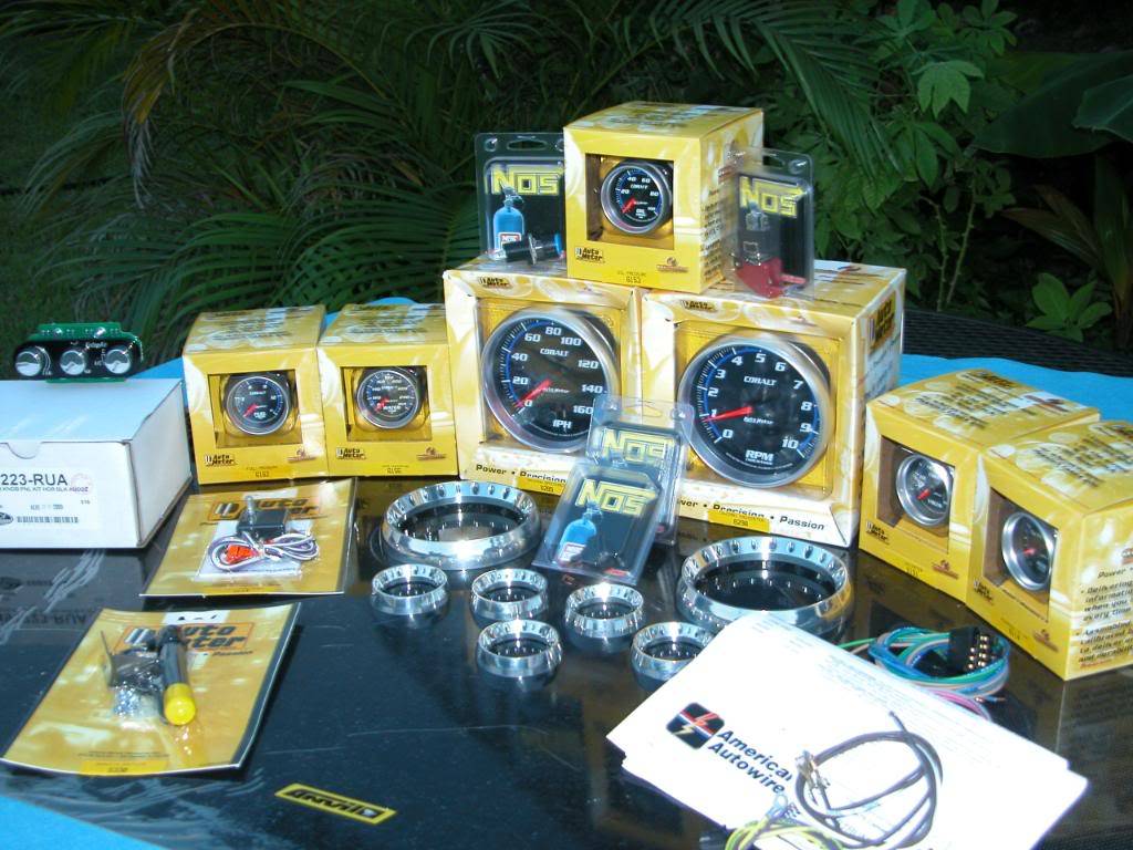
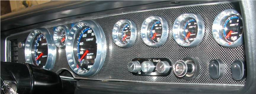
I recently built a custom carbon fiber dash panel assembly to fit in the stock 2nd gen dashboard of my friend Tys car, "Freedom Bird" which is being built at Fletchers Customs. The panel was made using Anvil Auto carbon fiber. Installed in the panel are, Autometer Cobalt gauges, Vintage Air controller, American Autowire headlight/lights switch, NOS arming switch, Pypes exhaust cutout switch, aftermarket delay wiper switch, and topping off everything is a set of Twist Machine billet gauge bezels.
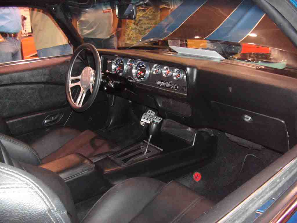
This thread will detail the "How To" so that anyone who wants to create a custom panel for their own car can see how it was done. The same procedures to fabricate and mount the panel could be performed using other types of materials for the panel. Below are a few pics of the panel as it was installed at the SEMA show.
A few things are not quite finished in the pics due to a show deadline and pieces which had not arrived in time for the show. A shift light will be installed in the space under the gas gauge between the Tach and Speedo, a billet bezel for the wiper switch, different toggle switches and a small "bird" emblem in the space next to the VA controller. The last post containing instructions in this thread will list the companies websites as well as tools and other things needed to complete the operations.

-
11-18-2009 #2
Registered User
- Join Date
- Mar 2007
- Location
- Florida
- Posts
- 2,391
The first thing you need to know is that this is not a quick project. If you don't have a lot of patience for detailed time consuming work stop reading now, just enjoy the pictures.
For the purpose of these instructions the gauge panel assembly and pieces will be refered to as follows
Bezel: The aluminum trim ring that surrounds the part with the gauge openings.
Facia: The flat part with the gauge holes in it.
Hood: The stamped sheetmetal section that has 3 screws holes where the upper part of the assembly is screwed to the upper dash.
Panel: The Bezel, Facia, and hood attached to each other as an assembly
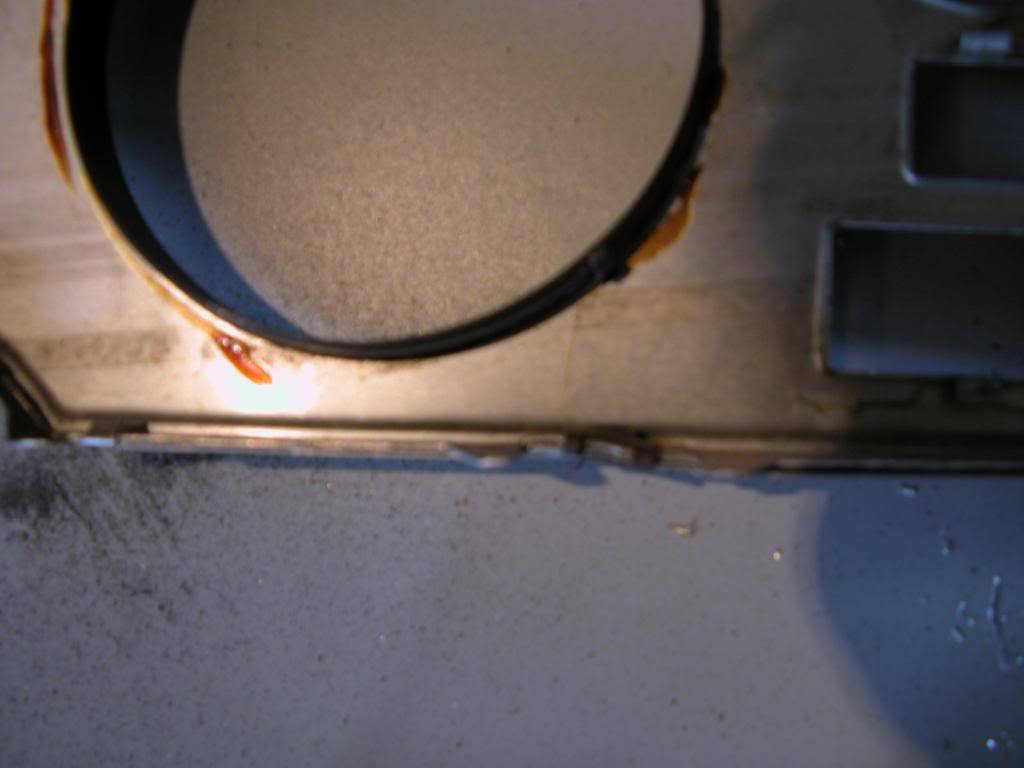
The first step is to remove the hood from the panel. This is accomplished by filing or grinding off the heads of the rivets holding it to the panel. Don't try drilling them out, it doesn't work well.
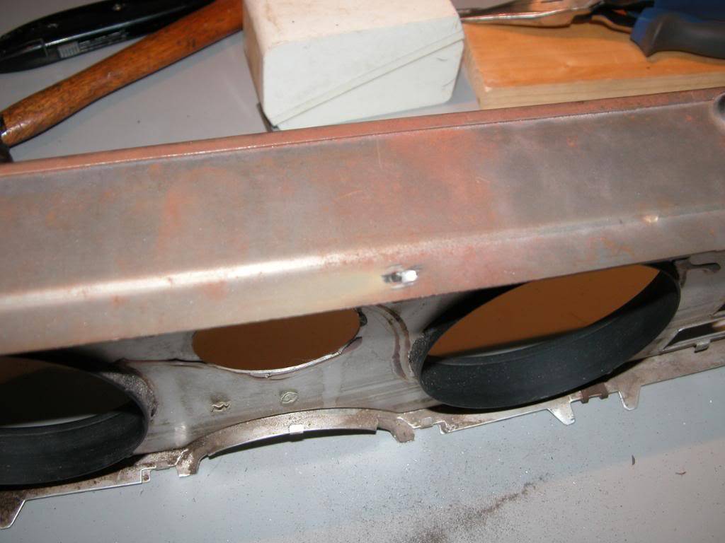
Once the hood is detached, remove the 2 screw clips on the bottom of the panel where the screws that come up from the bottom hold the panel in place when installed in the dash. Be very carefull not to bend or twist the bezel which might deform it enough to see from the front after reassembly. I find the clips are most easily removed using a dental pic and small pair of needlenose pliers. PUT THE TWO CLIPS SOMEWHERE YOU WILL NOT LOOSE THEM!
11-18-2009 #3
Registered User
- Join Date
- Mar 2007
- Location
- Florida
- Posts
- 2,391
The Bezel has several folded over tabs which hold it to the facia. These tabs need to be VERY GENTLY straightened out. This allows the bezel to be separated from the facia. Remove the bezel and put it in a safe place where it cannot get bent.
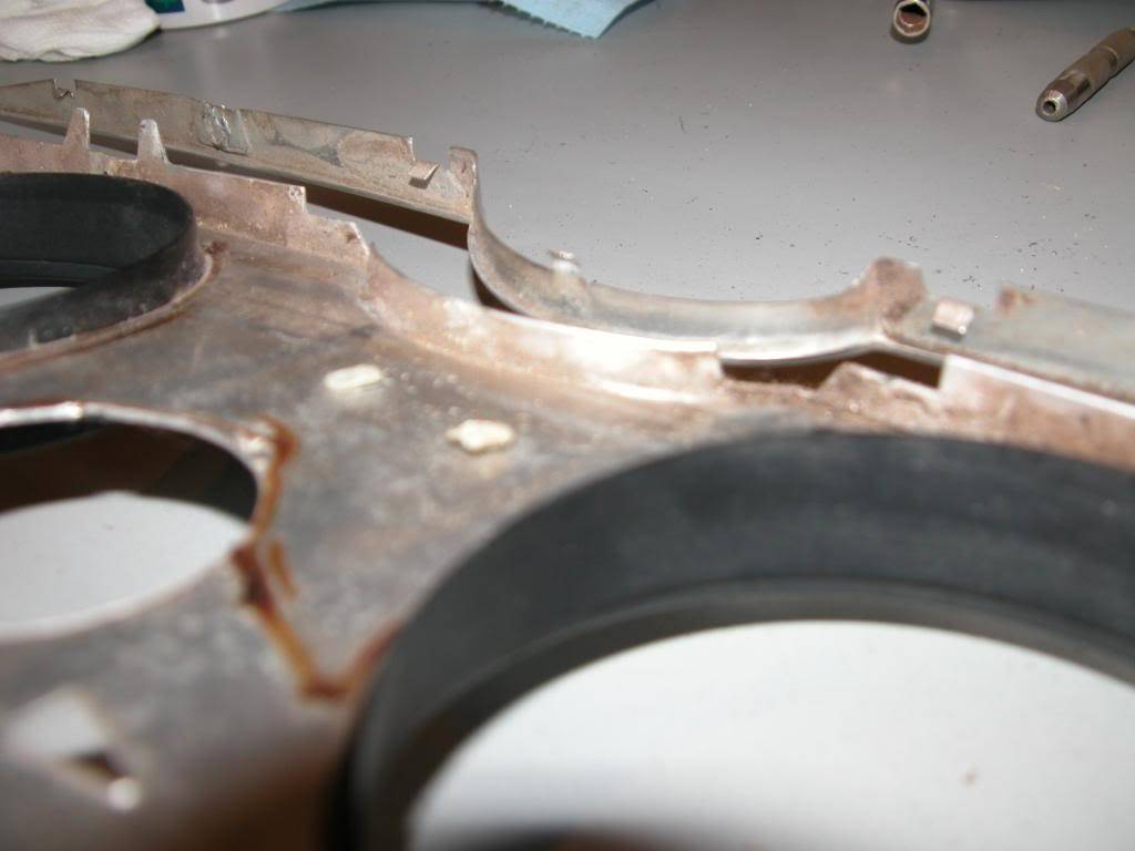
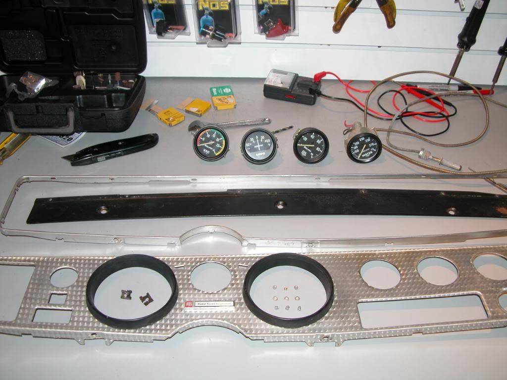
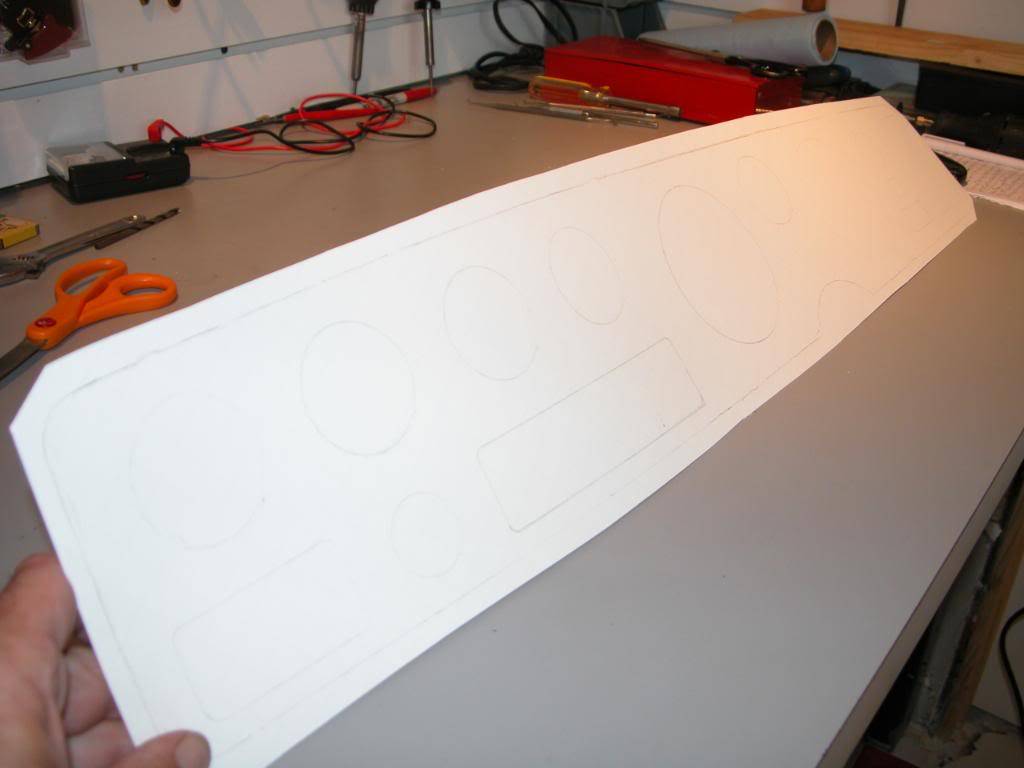
Wiggling the individual gauge rings will allow them to be removed from the facia. Also remove the Radial Tuned emblem. Once this is done get a piece of posterboard and lay the facia on it face down. Then put a heavy weight on it to keep it still and hold it flat to the bench.
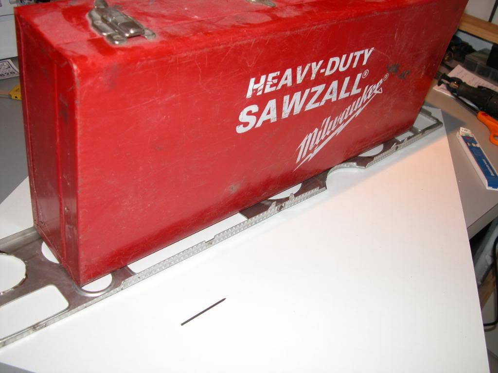
Use a pencil to draw an outline of the facia and all of the stock openings on the posterboard. It is important to mark all of the openings of the stock controls for reference when aligning things later. The panel does not have any straight lines on the circumference and even openings like the heater control section are not a perfect rectangle. all of the elements of the dash were figured out to make everything seem straight and level from the drivers position. Whoever designed the original dash did a fantastic job and must have put a tremendous amount of thought into the layout and design.
11-19-2009 #4
Registered User
- Join Date
- Mar 2007
- Location
- Florida
- Posts
- 2,391
Very carefully cut the shape of the facia out of the posterboard along the inner edge of the circumference line you made. Do Not cut out any of the openings for gauges etc. Sand the posterboard until you have an exact fit within the bezel. If you are off more than 1/16" you will have gaps where the posterboard does not fit perfectly into the bezel.
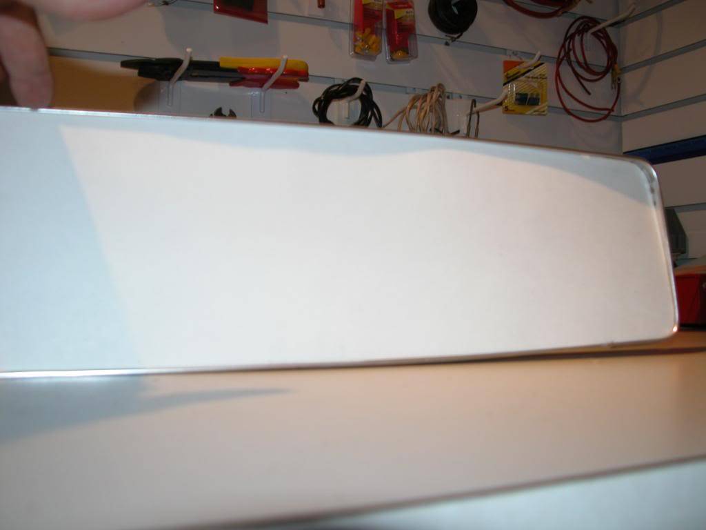
Now lay the posterboard cut out onto a thin sheet of ABS you'll be using for mock up. (If you're really confident in your skills and plan you could skip to the carbon fiber or final material you are going to use but I recommend fitting everything with cheap plastic first.)
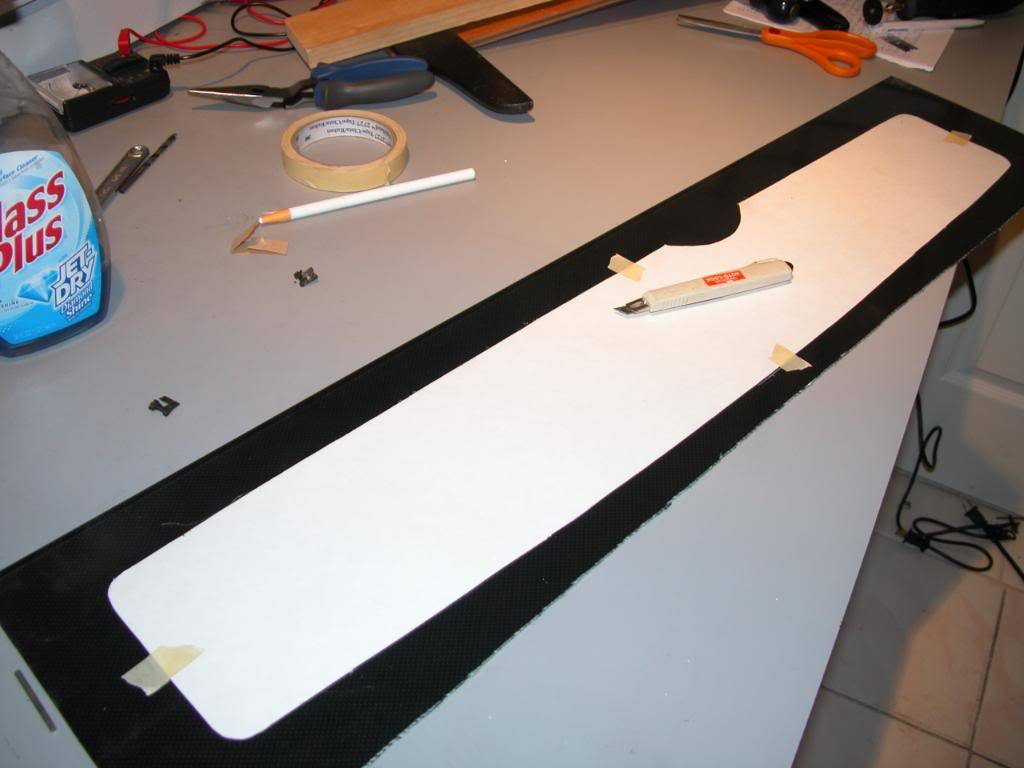
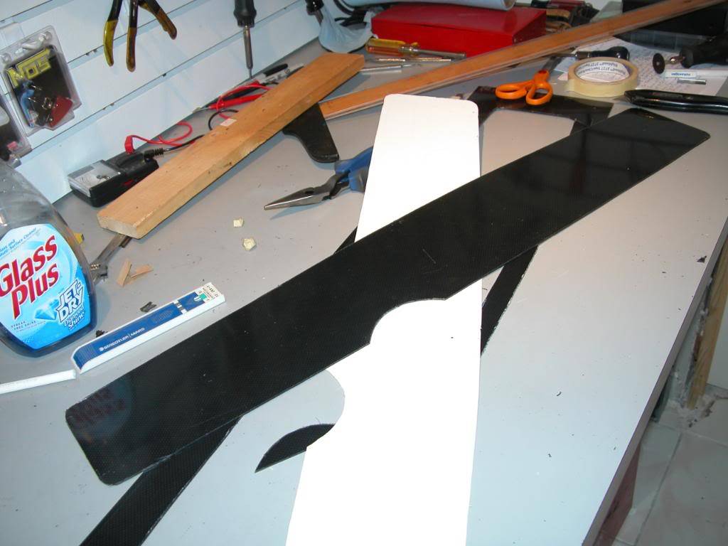
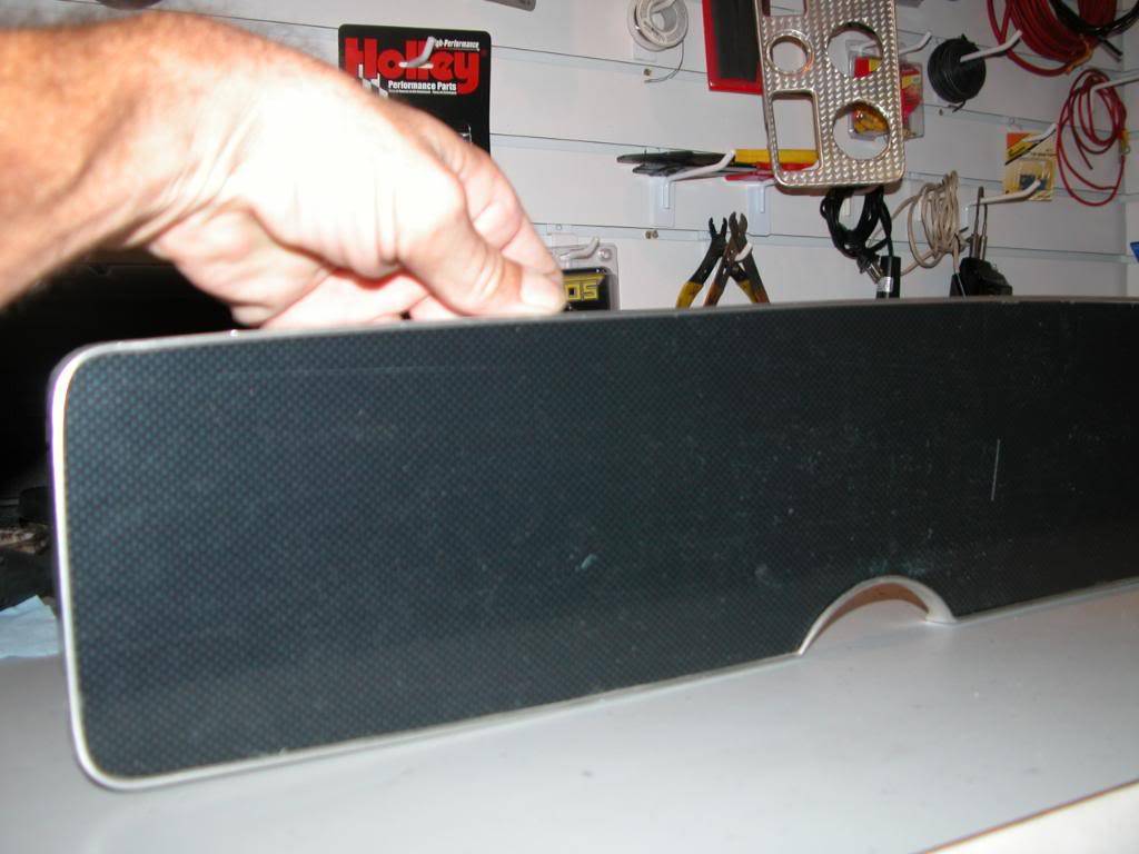
Tape the posterboard in place so it cannot move and trace the outline onto the plastic with a grease pencil. Then remove the posterboard and cut out the facia shape using a Dremel with a cutting bit. Do not try to cut it exactly to the correct size. After you've cut the shape out, sand down to its final size using 80 grit paper to fit perfectly into the bezel. The plastic shown in the pics is fake carbon fiber. It's very realistic looking but does not reflect light with the same prism effect of the real stuff.
11-19-2009 #5
Registered User
- Join Date
- Mar 2007
- Location
- Florida
- Posts
- 2,391
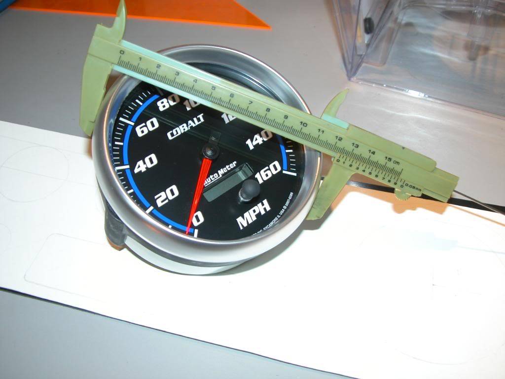
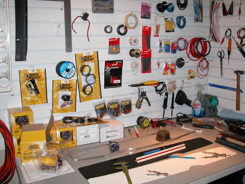
Now its time to plan where the new gauges will be placed. Use a ruler to line up the original gauge openings and locate the centers of the original openings. Next use a caliper to measure the outside dimension of the gauge trim ring on your new gauges and use a compass to mark the posterboard with the outline of the outside of the new gauge trim ring. If you are using 5" Tach and Speedometer units this will allow you to see if the tach needs to be moved toward the column a liittle to gain clearance because of the taper of the facia.
The Autometer 5" gauges aren't really 5" anywhere you measure them. I guess they call them 5" because they're about 5". Once you've determined where you'd like the Tach and Speedo positioned measure the gauge body right behind the trim ring and use a compass to mark the posterboard where the hole the gauge will need to fit into will be cut.
Next do the same thing for the slmaller gauges. If you're using the 5" - 2 3/16" combo then the gauge between the tach and speedo looks better if you raise it and the 4 side gauges look better spread out a bit.
Once you're sure where you'd like the gauges, cut out the holes from the posterboard.
11-19-2009 #6
Registered User
- Join Date
- Mar 2007
- Location
- Florida
- Posts
- 2,391
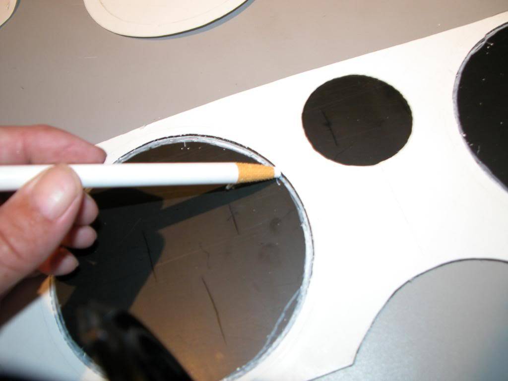
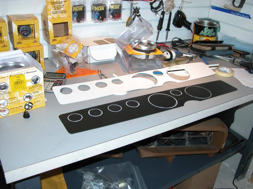
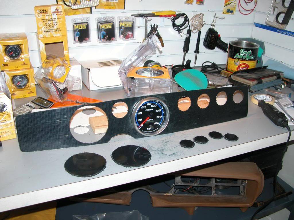
Use some 80 grit paper to sand the posterboard till each gauge fits into the hole. Keep in mind that the housing of each Autometer gauge is tapered a little from front to back so just because you can fit the back of the gauge into the hole you'll still have to widen the hole till you can slide the gauge housing all the way in to the hole until the gauge trim ring contacts the posterboard. Cut out the holes for the AC vent and lighter opening. The lighter opening needs to be oversized a little to allow variances when the final panel is installed. The trim ring for the lighter will cover gaps.
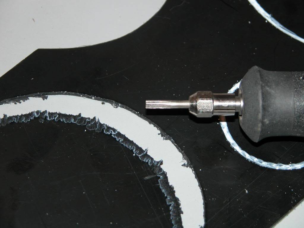
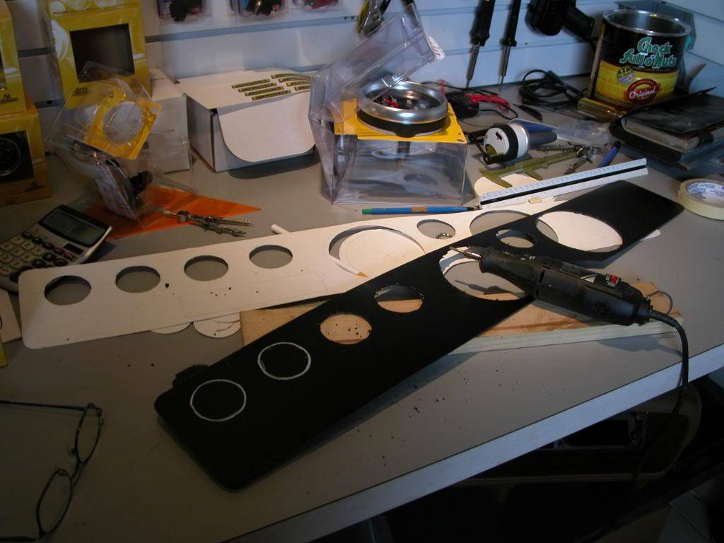
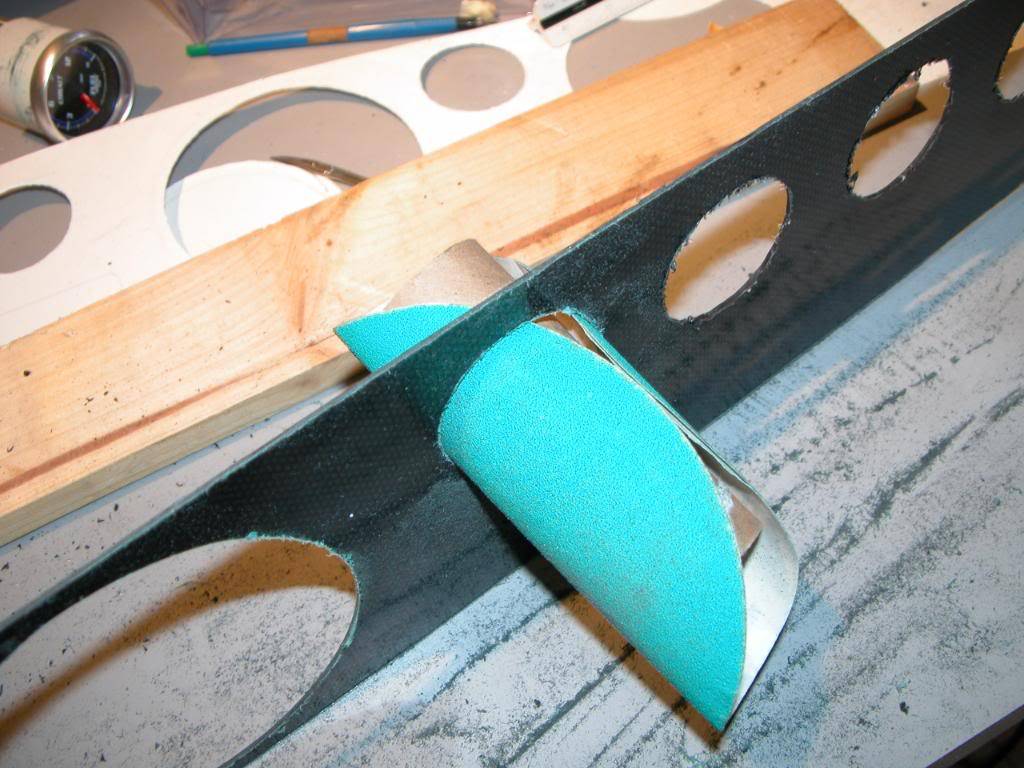
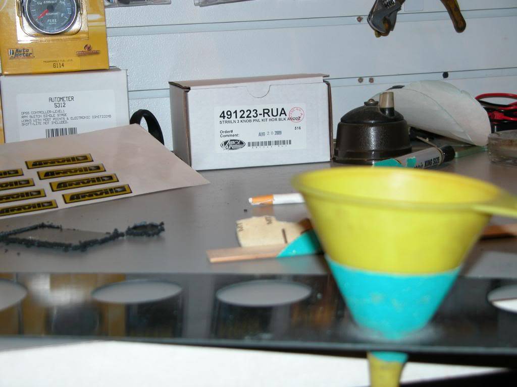
Once you've got the openings finished lay the posterboard onto the plastic panel and tape into place. Mark all openings with a grease pencil and cut openings with a Dremel tool keeping in mind not to open the holes up to much. You will sand the plastic to fit after cutting with the tool. I use something round to be sure I don't end up with egg shaped holes.
11-19-2009 #7 Registered User
- Join Date
- May 2008
- Location
- SoCaL-Pico Rivera
- Posts
- 1,138
Good job I may try this. for my chevelle.
---------Fabian Sanchez-----------
71 velle Project Syckness ATS,Rushforth wheels,PRRC, Autometer,UMI, Hotchkis,QA1,hood-latches.com, comp cams,
https://www.pro-touring.com/forum/sh...ad.php?t=43881
11-19-2009 #8 New to Pro-Touring
- Join Date
- Dec 2007
- Location
- PA
- Posts
- 75
Great idea on posting a “how to” thread!
This will help me out when I start my own insert/gauges in December.
Thanks! Project 69 Camaro: Chassisworks G-Bar, FAB-9 & sub-frame, Fesler Billet, ISIS wiring & LS3!
More pictures: http://camaro69vn10.com Updated!
Used to be known as Camaro69vn10
11-20-2009 #9
Registered User
- Join Date
- Mar 2007
- Location
- Florida
- Posts
- 2,391
Thank You! While this is about a Firebird dash a lot of the techniques can be used on many other types of dash panels so I hope it helps a lot of people over time when they're planning or building a custom panel. Originally Posted by markd

.................................................. ...............................................t
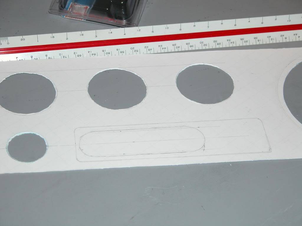
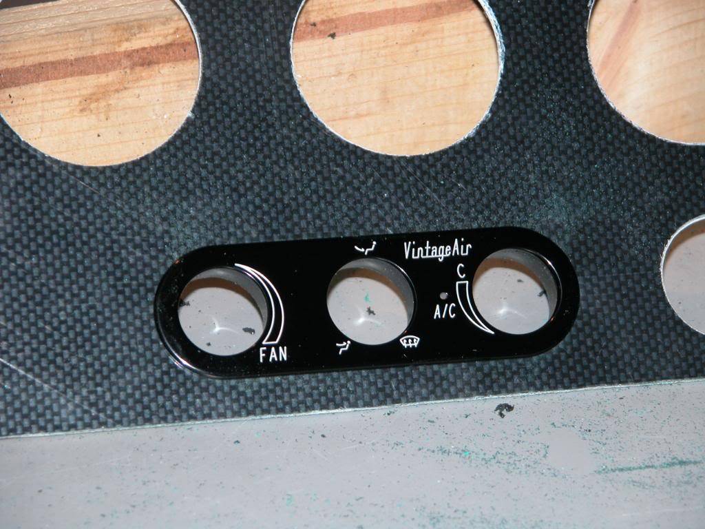
This dash panel will be using a Vintage Air (refered to as "VA" from now on) controller to operate the VA AC and Heat/defrost system. If you are using a stock heater control panel, mark the opening on the posterboard, cut, and then transfer to plastic and cut. If you are using a VA controller you will need to find the centerline of the original heater control panel by measuring on the posterboard and drawing a line. The line is used as a guide to keep the VA controller straight when deciding where you would like the VA controller positioned. Keep in mind that the circuit board assembly on the back is larger than the face plate and you have to keep the whole assembly high enough on the facia to provide clearance for the circuit board.
Once you've decided where to mount the VA controller place the face plate on the posterboard and mark the opening. Cut the opening on the small side and then sand the cardboard to an interference fit. It is important to the finished product that the hole for the face plate be exact. If the hole is too big the face plate may be able to slide around in the hole because of the way the face VA assembly sandwiches the facia to hold it in place. Once you have the VA controller opening where you'd like it, place the posterboard on the plastic panel and then repeat the process on the plastic.
Vintage Air provides a template in their instructions for people installing their controllers in places where the template would make it easier to locate the face plate. For this installation I would recommend not to use the template but rather just trace the actual face plate where it fits in the facia.
11-20-2009 #10 Registered User
- Join Date
- Mar 2009
- Location
- overseas
- Posts
- 3,434
very nice
 Kevin S. (overseas in Germany)
1963 Chevrolet Impala 2d ht Coupe
www.CruznArt.com
CRUZN - Automotive Artworks
11-20-2009 #11 Starting The Transformation
- Join Date
- Jul 2008
- Location
- Maple Ridge, BC,Canada
- Posts
- 113
very well done

What console is that in the car? Camaro?70 Nova - 406 sb -488 HP/504 TQ-3:73's
http://s66.photobucket.com/albums/h266/steelratnova/
11-20-2009 #12
Registered User
- Join Date
- Mar 2007
- Location
- Florida
- Posts
- 2,391
Thanks! It's a repro that looks like it was intended to allow it to be used in Camaros or Firebirds. It doesn't have the correct brackets to bolt it to the dash like the stock ones do. Originally Posted by Steelrat
.................................................. ..............................................
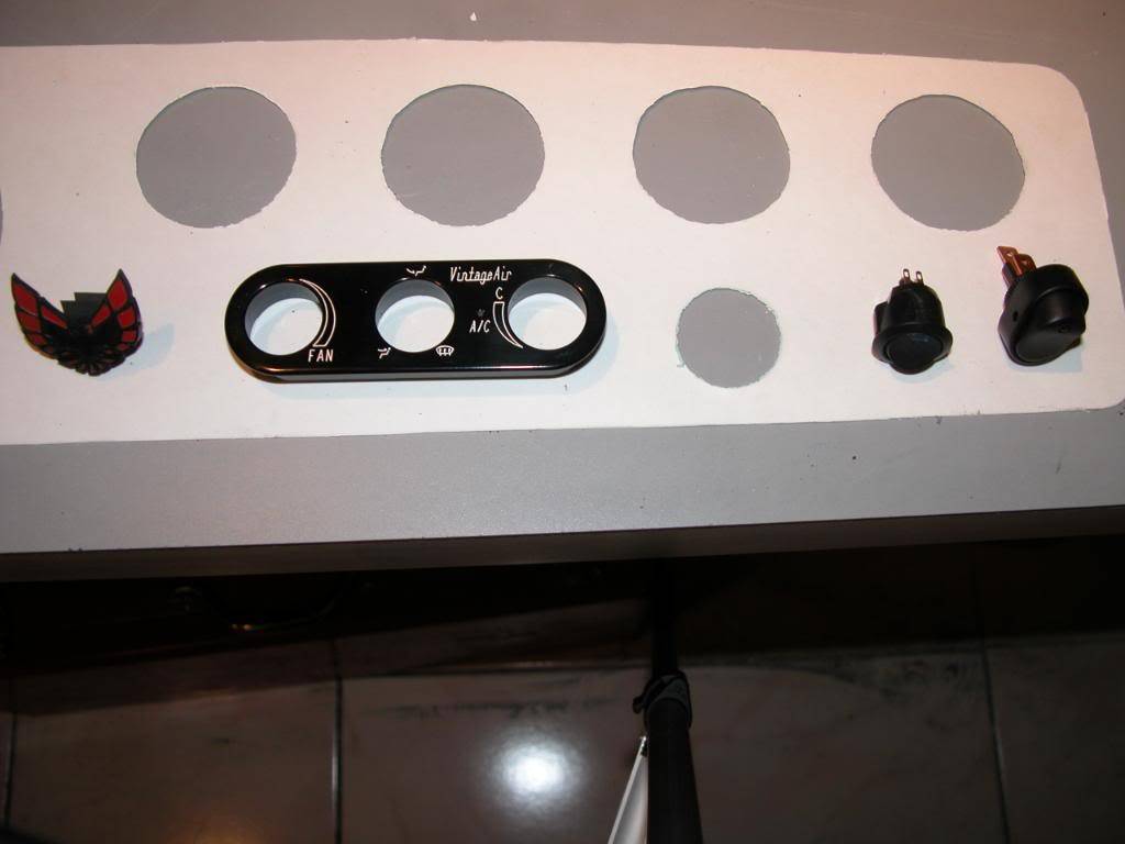
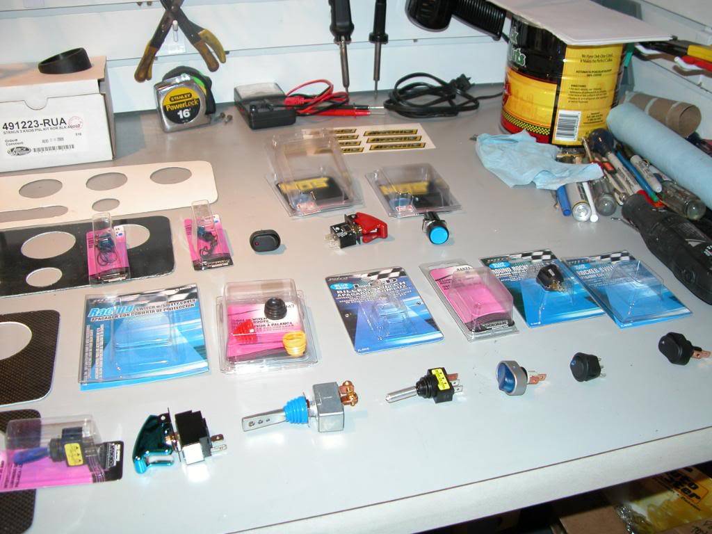
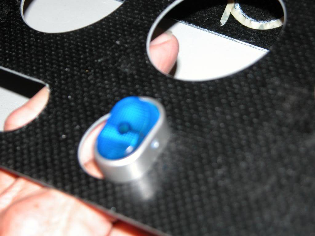
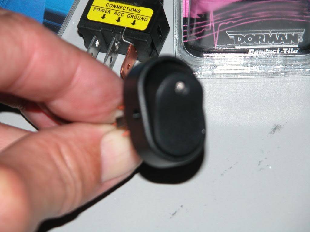
If you are mounting switches to the dash. The space to the right of the lighter is an excellent place, and is where the factory installed switches in some models. There's clearance behind the panel in that area for wiring. Now is the time to locate them on the posterboard and follow the steps to transfer their position till you have the holes drilled in the plastic to mount them. Turn signals also need to be located and holes made for them at this time. If you are using LED turn signal indicators be sure not to place them where they cannot be seen while driving. You don't want one or both blocked by the steering wheel etc.
I get an assortment of switches and return most of the switches quickly. I hold them up to the facia, gauges, and other items to see what will look the best. In this case none of them were "perfect" so the black with blue LED "on" indicator switches will be replaced with some billet ones to match everything else later. Sometimes you win, sometimes you don't! LOL The round blue NOS switch in the pic below is a momentary switch that will be mounted in the console to operate the line lock. The two "on/off" switches placed into the panel on this dash are going to operate the NOS arming mechanisms and the PYPES electronicly controlled exhaust cutouts.
11-21-2009 #13
Registered User
- Join Date
- Mar 2007
- Location
- Florida
- Posts
- 2,391
Now its time to set up the wiper and headlight switch area. The lights switch provided with an American Autowire update kit is the same mounting and wiring setup but has a cool chrome switch shaft and billet aluminum knob. Because it uses the same mounting and the same wiring connector as a stock original I'm using an old light switch in the mock up pictures and will install the new switch in the newly reconditioned dash from Restore a Musclecar when the dash and panel are installed in the car.
If you are using a stock wiper switch cut the light switch and wiper openings out of the posterboard, check to be sure everything lines up in the actual dash, then transfer to the plastic sheet with the grease pencil. Then cut and finish the openings.
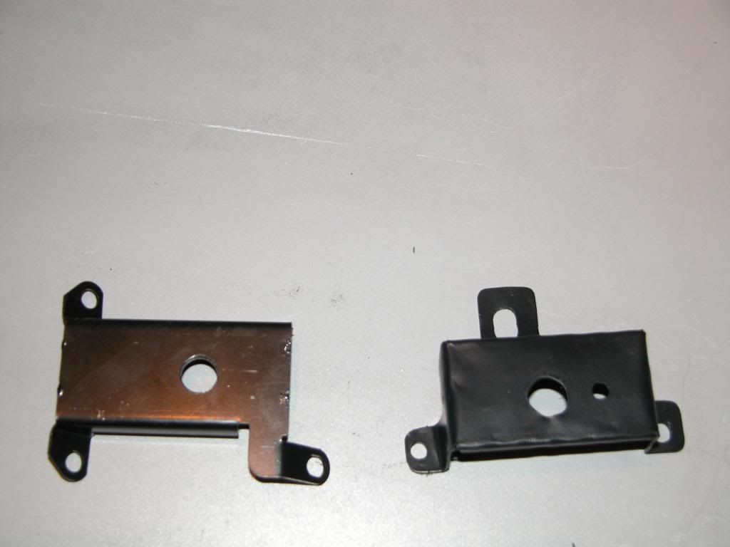
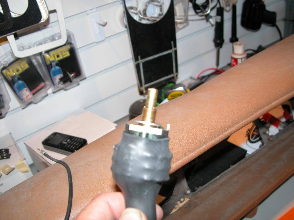
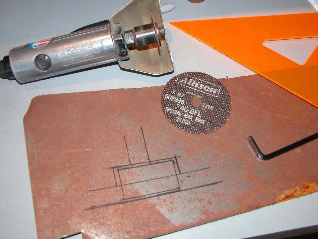
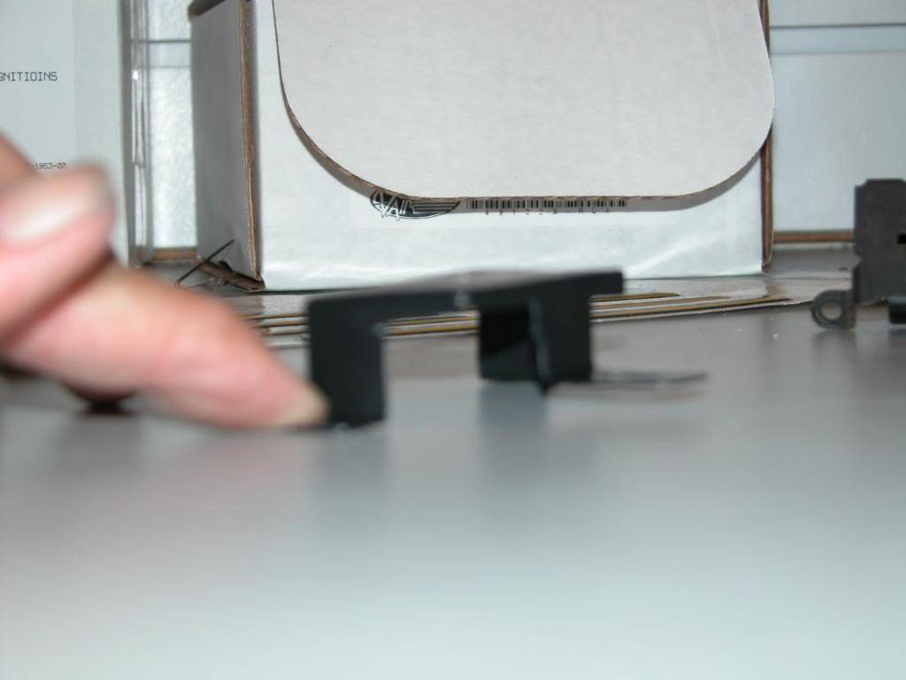
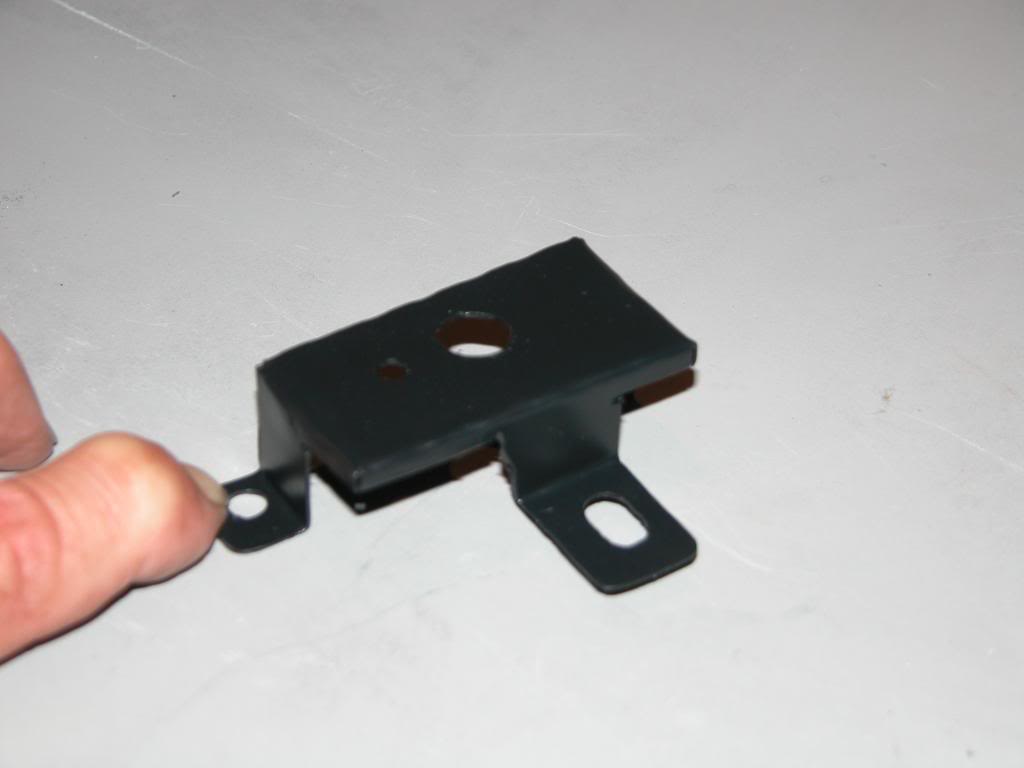
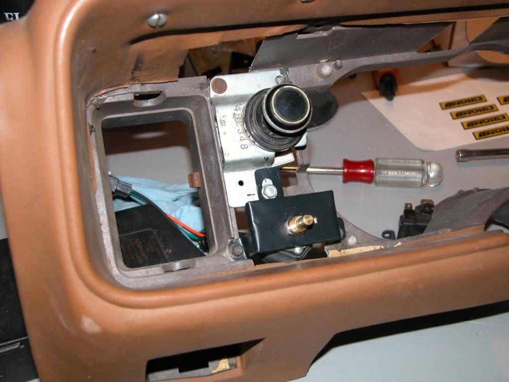
The aftermarket delay wiper switch is more of a challenge. The kit is made for Camaros of the same vintage and the mounting bracket provided will not work in a Firebird dash. A new bracket has to be made. The original wiper switch face was recessed into the dash. Because the front of the new carbon fiber facia will be out farther from the dash the bracket has to bring the new switch out far enough so the base of the switch shaft will end up flush with the backside of the carbon facia. A trim ring screws on the switch shaft after the panel is installed in the dash to cover the hole around the switch shaft.
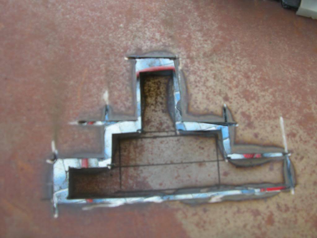
The dash framework under the wiper switch has to be clearanced to fit the bigger switch into the area where the old sliding switch was. Use a hand held hacksaw blade holder to cut the dash plastic then break off the pieces with pliers. If you try to move the wiper switch higher you will not have enough space for the light switch wiring harness which plugs into the bottom of the light switch. The camaro bracket is on the left and our new fabricated bracket on the right.
11-22-2009 #14
Registered User
- Join Date
- Mar 2007
- Location
- Florida
- Posts
- 2,391
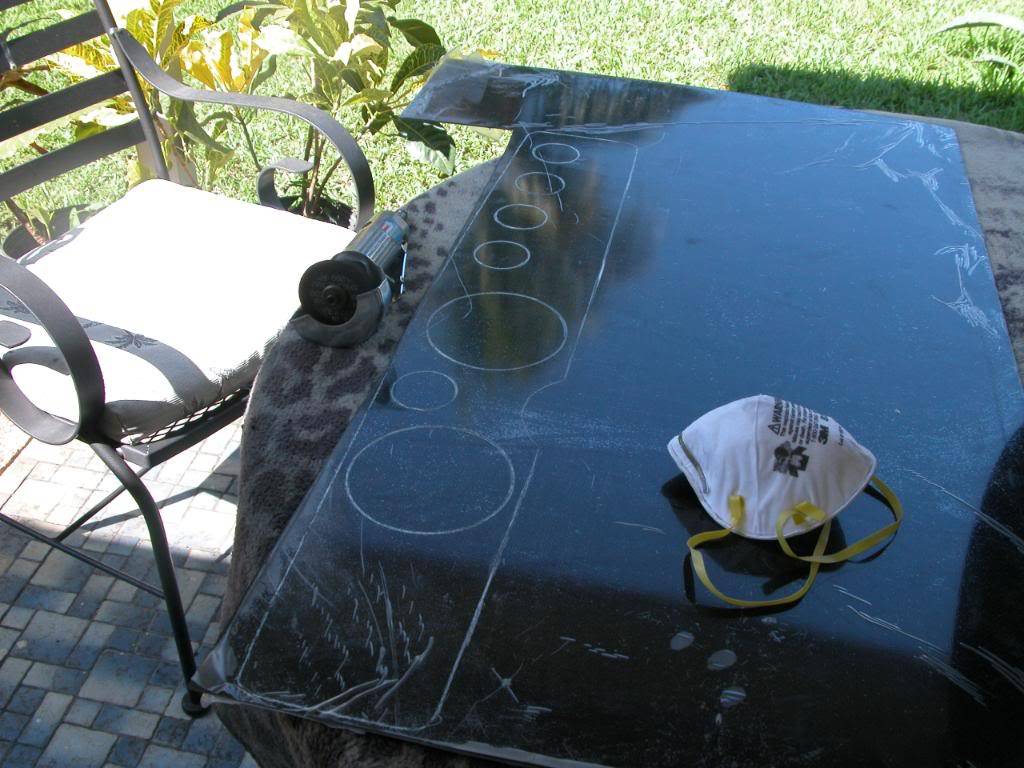
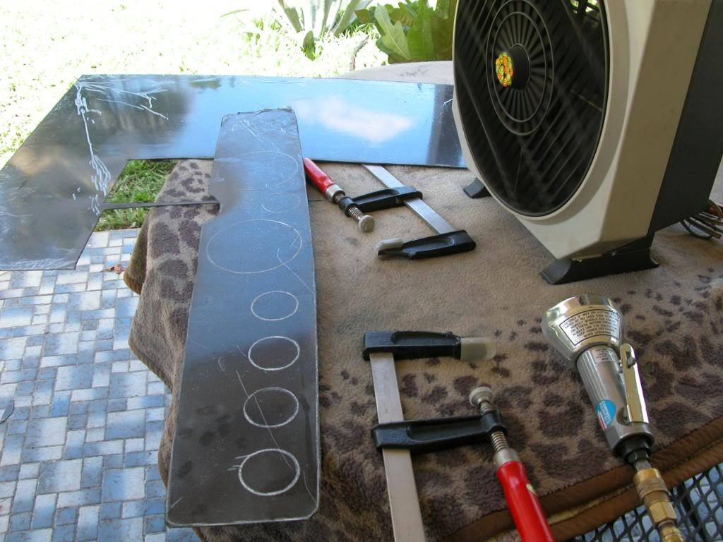
At this point you should have a plastic sheet with all of the openings you'll need for gauges, switches, turn indicators, and the vent. You can put the bezel on the plastic sheet and test fit it one last time in the dash. If everything looks good it's now time to use the plastic sheet as a template to mark the carbon fiber sheet that will be the new facia. The sheet comes with a protective coatiing on it. If you can't see through the protective film well you can remove enough of it to examine the carbon fiber for imperfections etc. in the weave. Most of these sheets are laid up by hand so there are minor variances in the appearance. Its not like the fake stuff with a perfect look. Also there may be minor scuffs or scratches from handling even with the protective coating. Minor scuffs or scratches can be fixed later if necessary by scuff sanding the surface then clear coating and polishing. Pick the nicest looking side and then lay your plastic template on it trying to line up any imperfections where they will end up where an opening will be cut out. Tape the plastic in place and mark the carbon sheet with a grease pencil.
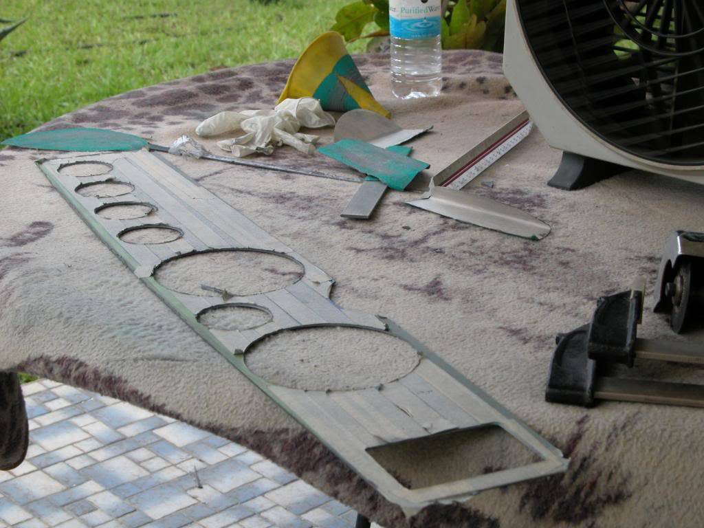
Cut the carbon fiber panel out of the sheet with a cutoff tool. Wear a respirator and eye protection. You may also want to wear latex or nitrile gloves as the fibers may irritate skin the way fiberglass does. You can not cut the carbon with a Dremel tool so forget even thinking about trying it. This is tough stuff as you're about to find out.
Last edited by NOT A TA; 12-04-2009 at 01:13 PM. Reason: add information
11-22-2009 #15
Registered User
- Join Date
- Mar 2007
- Location
- Florida
- Posts
- 2,391
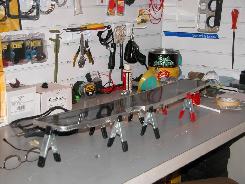
Now you need to file and sand the Carbon fiber (refered to as CF from now on) facia till you have an exact fit in the bezel. A fine toothed metal file works well to rough it in and then and finish with 80 grit sandpaper. When you think you've got the fit correct put the CF facia in the bezel and then put the original stock facia behind that and use some clamps to hold everything. This way you'll be able to check for a more exact fit.
The center area by the steering column can not be taller than the original facia or it will be very difficult to install the completed panel in the dash. It is easy to end up with the center of the panel too tall and have it still fit in the bezel when you are fitting it without the original bezel in place because of the flexibility of the bezel. If it is too tall there it will also be difficult to pop rivet the completed assembly together later so be sure the CF panel is exact.
11-22-2009 #16
Registered User
- Join Date
- Mar 2007
- Location
- Florida
- Posts
- 2,391
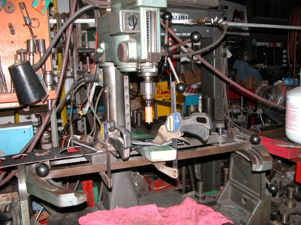
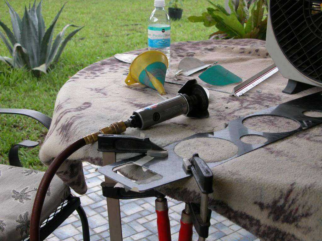
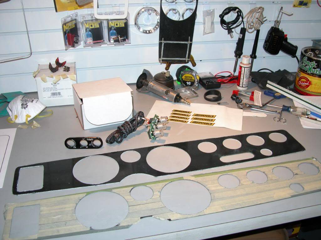
Now that you have the CF facia outline finished it's time to make all of the other openings. First cover the front side with masking tape so you don't scuff it or scratch it up. Cut the holes for the gauges with a hole saw using a drill press. Make sure you have wood under the CF facia and clamp it down when drilling. You will need Bi-metal hole saws to cut the holes. If you're using the 5" and 2 3/16" gauges you will need a 4 1/4", a 2 1/8", and a 1 1/8" for the lighter and headlight holes. Once the holes are drilled you will need to file and sand the openings to the correct dimensions.
You can cut out the vent and Vintage air controller openings with the cutoff tool and then file and sand to finish.
11-23-2009 #17
Registered User
- Join Date
- Mar 2007
- Location
- Florida
- Posts
- 2,391
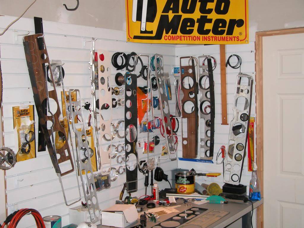
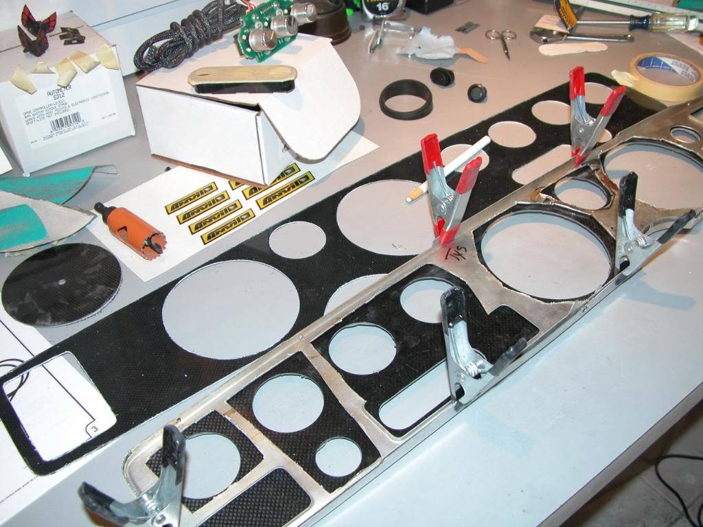
With the openings completed you will now be able to modify the original facia which will be used to provide support and allow assemble of the new panel. The idea is that the new CF facia will be sandwiched in between the leading edge of the bezel and the original facia. This is what holds the new CF facia in place, provides for stock mounting fasteners to be used , and allows you to use the bezel which gives the new panel the "look" because of the outline it creates around the CF panel.
Lay the CF facia on a bench and place the stock facia on top of that. Then you will see where you need to cut the stock facia to allow the gauges etc. to protrude through. You can cut the stock facia with a cutoff tool and then file to make it look neater and get rid of sharp edges you might get cut on or that might nick a wire. Be sure to leave vertical supports, do not cut out everything but the outside edge.
11-23-2009 #18
Registered User
- Join Date
- Mar 2007
- Location
- Florida
- Posts
- 2,391
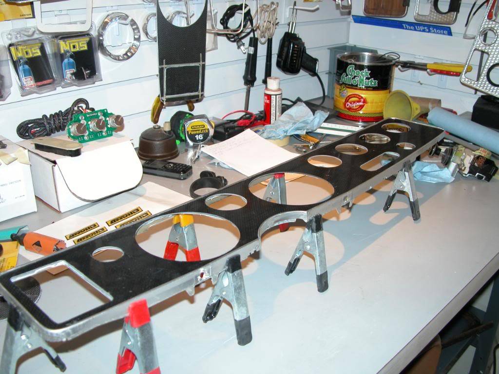
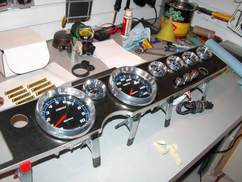
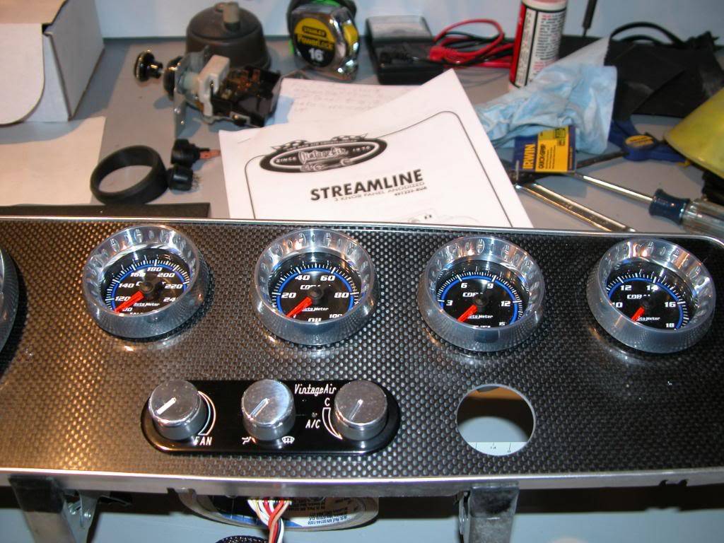
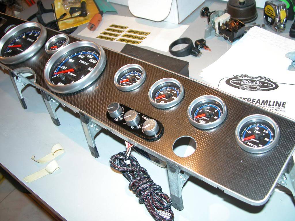
With the original facia now clearanced you can assemble the bezel, CF facia, and the modified stock facia then clamp them together. This will allow you to mock up the panel and have some fun seeing what your new dash is going to look like.
11-23-2009 #19
Registered User
- Join Date
- Mar 2007
- Location
- Florida
- Posts
- 2,391
Now that you've had a glimpse of the future for your dash it's time to get back to work.
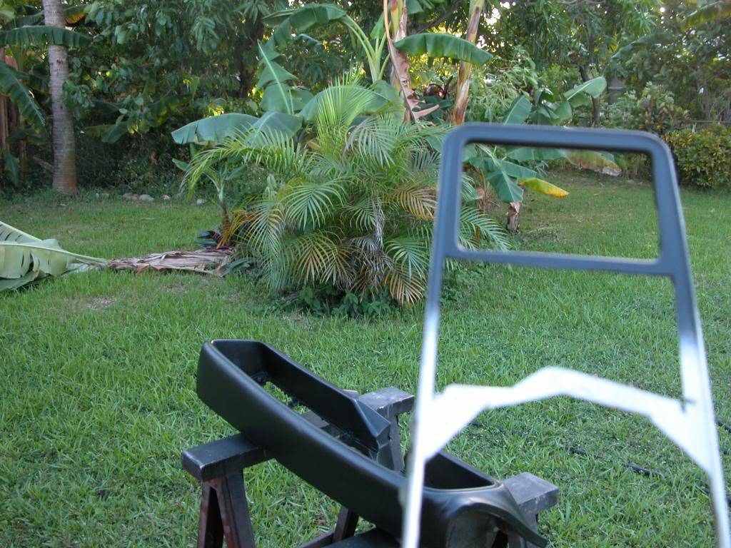
Take everything out and put all the gauges back in the boxes except one of each size along with one bracket for each that holds the gauge in place and 2 nuts, no need for lockwashers. Take the original facia and bezel off. Use some wax and grease remover to clean the original bezel in the area surrounding the vent hole then paint it flat black. You only need to do the area around the vent because the rest will be hidden but if the vent area is left shiny or wood tone you'll be able to see it after the panel is inserted into the dash.
11-24-2009 #20
Registered User
- Join Date
- Apr 2007
- Posts
- 2
very nice job

 Reply With Quote


