


Results 1 to 15 of 15
Thread: MIG beginner and I need advice
Threaded View


-
02-13-2010 #6

 Registered User
- Join Date
- Jan 2009
- Posts
- 197
So I got a chance to draw this up in solidworks and my idea looks like this:
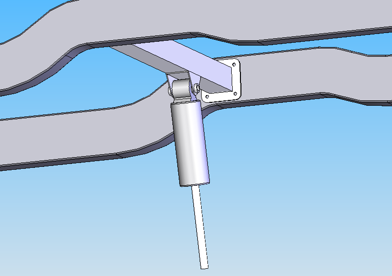
Note the following:
1)The cross member is 2X2 mild tubing, .083 wall thickness
2)The shock mount itself is fabricated from the same material
3)The screw spacers are .125" thick, .5" inner diameter, .75" outer diameter. These will be welded into place also
4)The end plates are 1/16" thickness (thinner than the tube, similar in thickness to the sub-frame rails)
The purpose of the end plates in my design is to make it easier for me to weld without burning through the sub-frame rails, and also to give an initial attachment point (hence the screw holes, I was thinking I could initially attach the frame with sheet metal screws and check for fitment, squareness, etc before really committing to welding it in.
Any criticism of my design is welcome. Thanks!
-

 Reply With Quote


