


Results 1 to 6 of 6
-
11-18-2009 #1

 Registered User
- Join Date
- Jan 2009
- Posts
- 197
Where can I find Adjustable Sway Bark links
Hi guys.
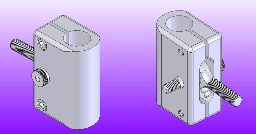
Where can I find commecially available sway bar adjuster links like the ones I drew up below? I will make them if I have to but I would prefer to buy this or something like it if I can. Thanks!
-
11-18-2009 #2 Registered User
- Join Date
- Aug 2004
- Location
- Rustburg, Virginia
- Posts
- 3,436

For the Front bar?
1970 RS/SS350 139K on the clock:
89 TPI motor w/ 1pc rear seal coupled to a Viper T56 via Mcleod's modular bellhousing w/ hydraulic T/O bearing from the Viper, 12 bolt rear w/ 3.73 gearing, SC&C upper control arms, factory lowers with Delalums, C5 brakes at all four corners, Front Wheels 17x8's with Sumi 255/40/17 and Rear Wheels 17x9's with Sumi 275/40/17.
Brief description of the work done so far can be found here: http://www.nastyz28.com/forum/showthread.php?t=112454
11-18-2009 #3
Registered User
- Join Date
- Jan 2009
- Posts
- 197
Front or rear. Front 1.125 diameter, rear .875 diameter
11-18-2009 #4 Registered User
- Join Date
- Apr 2009
- Location
- san diego
- Posts
- 5,101
good design. i have personally never seen anything on the market like that. however this is the closest I have seen.
http://www.totalcontrolproducts.com/...812-M10_AT.jpgMy build thread: https://www.pro-touring.com/showthre...ing&highlight=
The mustang build thread: https://www.pro-touring.com/showthre...el)&highlight=
11-18-2009 #5 Registered User
- Join Date
- Nov 2008
- Location
- So. Cal.
- Posts
- 1,240
Nice drawing!!! What is the reason for them. What will they do that you are missing from an available mount. Im not being critical, just curious. I like the drawing, makes me jealous. I have a hard time just making a rectangular block on the CAD. They are a nice simple design. Quick work on the mill. What is that lil two stepped nipple below the rod end. A zerk? A lil more info on your needs would be cool cause Im interested what you have planned. Bet its gonna be good. JR
11-19-2009 #6
Registered User
- Join Date
- Jan 2009
- Posts
- 197
Thanks for the props! Originally Posted by JRouche

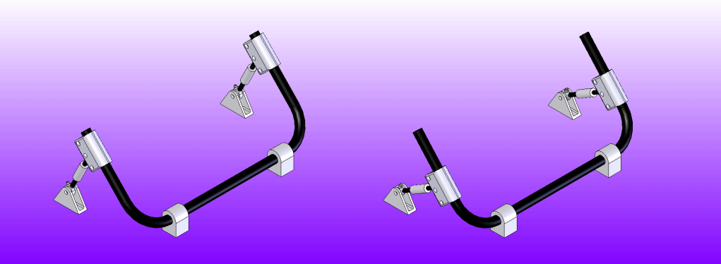
The reason for them is that they act as a movable point of attachment for the sway bar. I drew this up for purposes of comparison. Its not exactly to scale, but it is close enough to illustrate the concept.
Also, yes it is a zerk fitting.
Here you can see conceptually how the system works. In the image on the left, the sliders are moved outboard from the sway bar pivot, in the image on the right they are adjusted inboard.
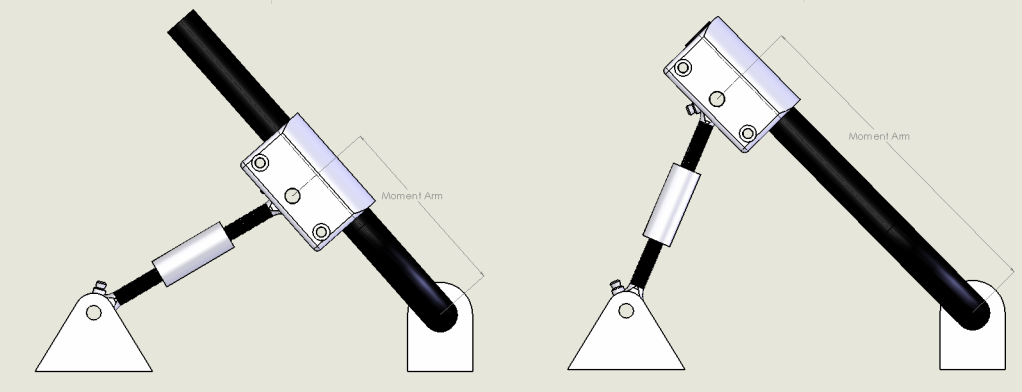
Here you can see how this affects the moment arm of the sway bar system. Basically when the moment arm is shorter, the sway bar will act stiffer, when it is longer, it will act less stiff.

 Reply With Quote