Enter your username:
Do you want to login or register?
  • Forgot your password?

    Login / Register


    Results 1 to 16 of 16
    1. #1
      Join Date
      Apr 2007
      Posts
      175

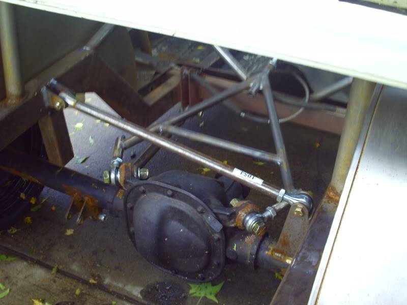
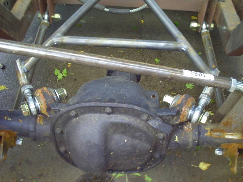
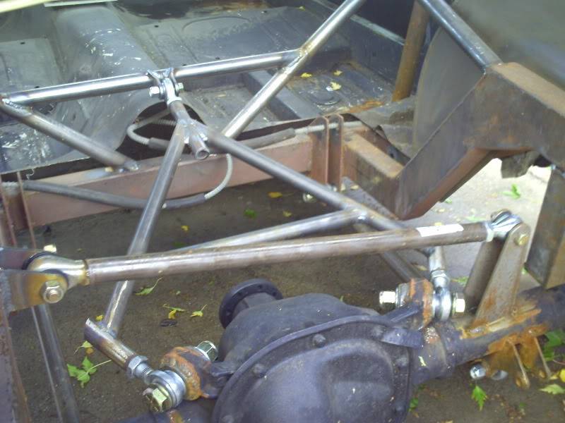
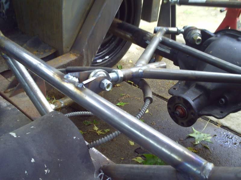
      3-Link for my 65 Mustang

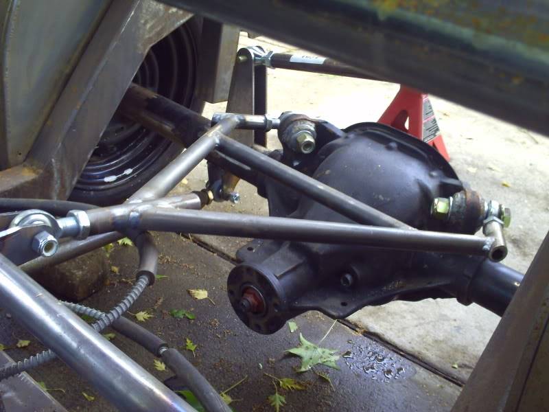
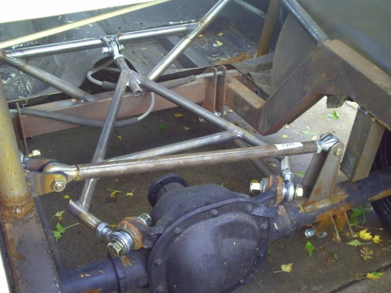
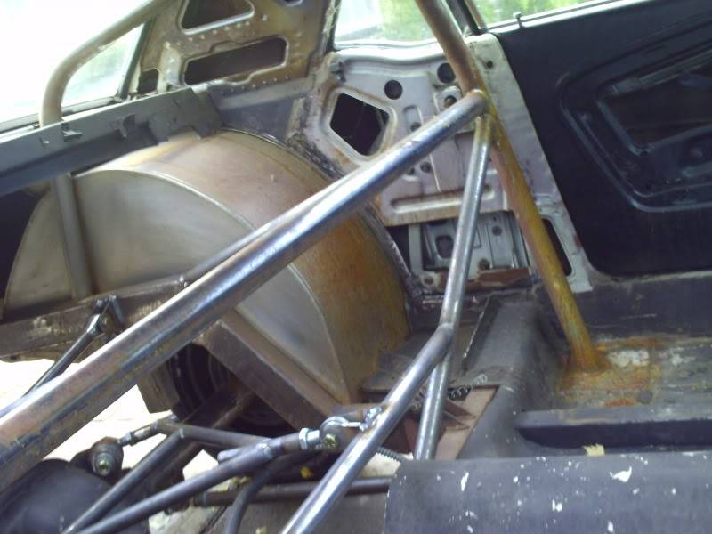
      Heres some new pics
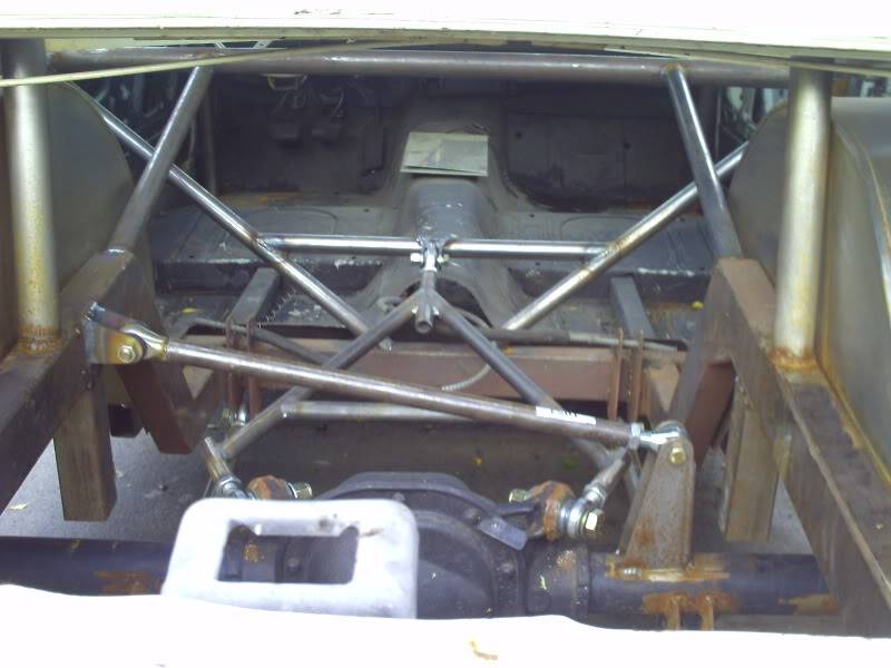


      Last edited by baggins; 10-14-2009 at 06:13 PM. Reason: title


    2. #2
      Join Date
      May 2007
      Location
      Orlando, FL
      Posts
      215
      This is going to cause a lot of confusion with that other thread!

      Are you certain you can use that high a roll center?

      What antisquat range do you cover with your adjustment holes?

      At what antisquat percentage do you get total driveshaft torque cancellation?

      Don't forget that single lower link is carrying about double the load a single upper link would carry.

      Others will probably pick at you on strength issues, but, as far as function is concerned, it looks great.
      http://www.racetec.cc/shope

    3. #3
      Join Date
      Aug 2004
      Posts
      2,413
      I see two lowers and a wishbone upper Billy.

      I also saw that panhard way up there and thought it was to high..
      Mine will be at the bottom even with the lowest most point of the pumpkin so I can still get a jack under it.

      Strength issue ad the point where the upper link connects to the crossbar in the center. It should be triangulated at that point. And the heims are of the budget type. Will wear fast and arent very strong. othere than that looks like a plan.
      Nothing says "I built this" better than tool marks and dykem blue..

      Follow my 3 link build. https://www.pro-touring.com/forum/sh...ad.php?t=61592

    4. #4
      Join Date
      Jul 2007
      Location
      Olathe, KS
      Posts
      1,158
      Country Flag: United States
      I would agree about the high roll center. I'd be interested to know the logic behind it.
      Looks like you made good use of the factory mounts on the rear. Is that a fox body 8.8?
      What are you planning on doing for springs/shocks?

    5. #5
      Join Date
      May 2007
      Location
      Orlando, FL
      Posts
      215
      Quote Originally Posted by LowBuckX View Post
      I see two lowers and a wishbone upper Billy.
      These old eyes are failing me. The last picture shows that lower left link.
      http://www.racetec.cc/shope

    6. #6
      Join Date
      Jun 2001
      Location
      Orlando, FL
      Posts
      10,604
      Country Flag: United States
      For performance handling, the high panhard is a show-stopper. It needs to be 3-5" below the axle centerline.

      jp
      John Parsons

      UnRivaled Rides -- Modern upgrades for your ride.

      UnRivaled Rides recent project -- LS9-powered 69 Camaro

    7. #7
      Join Date
      Aug 2004
      Location
      Boston MA
      Posts
      686
      You've taken a 4 link drag clip and scabbed a top link on to it. What's the purpose/ goal of the car?

      Irrespective of the short/ high panhard bar and the third link that appears to be angled upward, it's structurally scary. I'm not going to list the reasons but if you make 300hp on a 8" rear wheel, you'll destroy the thrid link and it's mount.

      This is a pretty famous thread that will provide you with the concepts needed to build car-bits that are safe. http://www.corner-carvers.com/forums...ad.php?t=27556

      Maybe some one can suggest a good book on basic structural design theory?
      1967 #s RS

    8. #8
      Join Date
      May 2007
      Location
      Orlando, FL
      Posts
      215
      A lot of the strength issues would be dismissed if all that triangulation business was eliminated and a center mounted rear support was fabbed for a simple single upper link.

      Again, pardon the old eyes, but I can't make out any alternate mounting holes for the fronts of the lower links. This presents a problem if the car is sitting at ride height and that upper link is indeed angled upward, for it appears the lower links are angled downward. Now, there's nothing wrong with intercepting the desired antisquat line at a point forward and up (except for roll oversteer problems, that is), but you've got to give the lower links a chance to make the connection.
      http://www.racetec.cc/shope

    9. #9
      Join Date
      Apr 2007
      Posts
      175
      i guess i should have stated this is still a work in progress. I appreciate all the input and for sure some changes are going to be made. But i can say that the car is not at ride height.

      Also I have not seen any pictures of an 8.8 with just a regular center upper link can somebody post a picture

      Thanks Nick

    10. #10
      Join Date
      Apr 2006
      Posts
      134
      Well, here's my DIY. Tough to see.


      http://members.shaw.ca/pekpress/3Lin...sandstuff.html

      That upper is going to flex near the rod ends. Would the rod fit on the insides? Even so, unconventional.
      Upper should also be 2/3 the length of the lowers.
      Lowers should be out as much as possible.
      Roll Center way too high.
      Geometry should be calculated out to give you the performance you want.

    11. #11
      Join Date
      Dec 2007
      Location
      Carlsbad, Ca
      Posts
      1,213
      Country Flag: United States
      i think it would work a little better if you tied the two ears together to make a solid mount over the center, or slightly offset, of the pinion. you could then tie your link into this mount, and it would eliminate the wishbone. with the current angles, there is no way for that link to fully articulate without binding. it may work for the given travel range, but i would look at designing it a little different.

      if it were me, i would scrap that housing all together and get one that you can weld to.
      Tim

      The WidowMaker: Garage Built 70 Chevelle

      Special Thanks To: Rushforth Wheels, MuscleRodz, Kore3 & SC&C

      Build Thread Link

    12. #12
      Join Date
      May 2007
      Location
      Orlando, FL
      Posts
      215
      "terryr" should have directed you to the page at his site where the bracket is shown that he used for the rear mount (about 1/5 of the way down the page):

      http://members.shaw.ca/pekpress/3Lin...sandstuff.html

      I would strongly recommend that you look at his site. Like me, he's starting with free site space. He's an excellent writer and even your wife or girl friend would find it interesting. (Except when he starts talking about his 13 inch member.)

      I'll try to clear up the confusion on antisquat about 4/5 of the way down terryr's page: The percent antisquat is the percentage of the weight transfer that is carried by the links during forward acceleration. This means that, if you multiply the slope of the line of action of the tire patch force vector...as deterrmined by the horizontal force component and a vertical force component defined by the vertical load carried through the links...by 100, you have the percent antisquat. When considering ONLY the dynamic forces carried through the links, the resultant will ALWAYS pass through the instant center. So, the percent antisquat can be determined by the location of the instant center. If the instant center is above a line passing through the tire patch and the intersection of two other lines, one a vertical line through the front tire patch and the other a horizontal line through the center of gravity, the percent antisquat is greater than 100; if below, less.

      The above assumes that the weight of the rear axle assembly is negligible compared to the overall car weight. If this is not the case, the 100% antisquat line passes below the rear tire patch at a distance equal to the tire radius multiplied by the ratio of rear axle assembly weight to the weight of the remainder of the car. (This effect is usually ignored, even in automotive engineering reference books.)

      And, of course, all of the above pertains to a RWD beam axle car.

      Incidentally, terryr, my site has a free instant center spreadsheet. No pretty pictures, though. I don't know why there should be so many different answers. It's just high school algebra.
      http://www.racetec.cc/shope

    13. #13
      Join Date
      Dec 2007
      Location
      Carlsbad, Ca
      Posts
      1,213
      Country Flag: United States
      terryr's bracket is the style im talking about. still not perfect (a new housing would be perfect), but much better and a TON less flex.

      Tim
      Tim

      The WidowMaker: Garage Built 70 Chevelle

      Special Thanks To: Rushforth Wheels, MuscleRodz, Kore3 & SC&C

      Build Thread Link

    14. #14
      Join Date
      Jun 2001
      Location
      Orlando, FL
      Posts
      10,604
      Country Flag: United States
      I think the upper frame bracket can be fixed by tying it into the driveshaft tunnel in a load spreading method.

      But the high panhard has to go.

      jp
      John Parsons

      UnRivaled Rides -- Modern upgrades for your ride.

      UnRivaled Rides recent project -- LS9-powered 69 Camaro

    15. #15
      Join Date
      Apr 2006
      Posts
      134
      Quote Originally Posted by BillyShope View Post
      (Except when he starts talking about his 13 inch member.)

      Incidentally, terryr, my site has a free instant center spreadsheet. No pretty pictures, though. I don't know why there should be so many different answers. It's just high school algebra.
      http://www.racetec.cc/shope
      The women might find that more interesting.

      I've used formulas from several people including yours. Why they don't agree is a good question. Y'all get together and sort it out.

      From a practical point of view, the 3rd link has been in for 11 months and I'm happy with it. So no more changes.
      For now I'm going to work on my turbo-encabulator.

    16. #16
      Join Date
      May 2007
      Location
      Orlando, FL
      Posts
      215
      Quote Originally Posted by terryr View Post
      The women might find that more interesting.
      Yes, I realized later that I had stated that backwards.

      Terry, I've sent you a PM.
      http://www.racetec.cc/shope


    Advertise on Pro-Touring.com