


Results 21 to 40 of 41
-
03-30-2005 #21

 Starting The Transformation
- Join Date
- Aug 2004
- Location
- CA
- Posts
- 452
I think your car will look good with splitters, rear wing, and diffusers (seriously). Kinda like LMP car with vintage Mustang body. You'll probably want them when you unleash 800hp at PR anyway. BTW, your car is far from jalopy. It's one of my favorite early Mustangs for sure, and the fact that you use your car like it's intended makes it even better!
I seem to recall reading something about deep hats causing some unwanted rotor deflection or cracking or something. But the info is probably outdated, as I'm pretty sure it was in either Donohue's or one of Caroll Smith's books. Both design and metallurgy have improved. FWIW, TA cars are just like yours - tall hats, monster Brembos, and rims with as much + offset with not much (if at all) caliper overhang. It's probably easier to design spindles that way (bearing/pin loading, spindle rigidity, etc), easier to change tires (centerlock nut more outboard), and perhaps there's slight advantage in brake cooling with the rotor being closer to ducting. EDITOops, never mind. Rotor will be in the same location for given rim and scrub radius.
Late model OE bearings are much different. The pin is a part of hub forging, and sealed bearings are pressed into the bearing housing, which bolt on to the knuckles. I'm sure you know all that. The pin is rather short - I think it works b/c rim offset is designed such that wheel centerline falls near the centerline of bearings. IMHO, using neutral offset rims with those bearings, like many Corvette transplants on street rods, is a big no-no. But then again, I've seen a late model S10 4x4 with negative offset rims getting pounded offroad w/o bearing failure so what the hell do I know? The advantage of this design is it accepts wider range of rims, I guess, as there's no pin snout to stick out (just registering boss). Possible disadvantage is heavier rotating mass since the pin rotates (though it's damn near the centroid), and you're stuck with steel hubs as opposed to aluminum. But then again, shallow hats are lighter too.
With either design, caliper mount usually ends up close to the main body of knuckle, if things are designed right. I guess these are just different ways to accomplish the same goal for the most part.
Now if you can get rims with +3" or more offset with good overhang clearance, you'll be able to use shallow SAI and still end up at very small scrub radius...But more than likely the improvement is nil, and wheel spokes sticking too far from tire sidewall would hinder aerodynamics rather badly and designing rigid A-arms with rim clearance would be a major bitch.
I wish I had unlimited money and resources to conduct extensive R&D...All this stuff really fires up my curiosity.
Now this is a good tech talk! Where are Mean69 and Norm when we need their perspectives?
Would you let me know when you go out to track next time? Shoot me a PM over at CC.com. I definetely would like to check out your car. I'll be in WA until summer.The first step of becoming a better driver is to attend a track event, time yourself, and realize the fact you really suck.
Signed,
A driver who laps Big Willow at 1:42.6 in a 134hp BMW - and I am still considered mediocre.
-
03-30-2005 #22
Registered User
- Join Date
- Dec 2004
- Posts
- 333
Thanks for the education - I knew the Corvette style hubs bolted on but I didn't realize how different the construction was from what I did, and hadn't even considered all the engineering ramifications. Like I said before even if you understand this stuff it seems like there's always lots to learn. I did base the car a lot on TransAm style construction so that's probably how I ended up making the right decisions. I know one thing that Sierra Caliper I have is pretty damn wide. I"m thankful for everything I've learned but if I started over I'd just build a C5 based setup, I don't see where my design really gained me much in the end other than clearance for 12" wheels.
Car does have the small splitter already and rear diffuser. For now I leave the underengine and underaxle flat panel out for cooling and noise reasons when I need the extra lap time I'll start experimenting with it. At one time I was gonna do a front diffuser but without testing/CFD it would be pointless and I needed the real estate for the IC.
Splitter comes off easily so I could easily put something much bigger on for the track and I have hard points to support it with heim links on the bumper mounts.
I"m glad you mentioned the wing thought I've been really torn between just putting a big adjustable spoiler on it or a wing. If a wing it would be a real TransAm wing or some such. Just not sure if it would work on the vintage stang. Even a big spoiler would look really race car-ey - other option is just put on the standard Maier fiberglass trunk lid with small spoiler for aesthetics. Steel trunk lid weighs 30 lbs so the fiberglass lid is sort of on my list anwyay. Of course I would like an electric ram controlled spoiler so I could have an air brake !!
I guess I know the wing is much more efficient in the long run, probably best combined with the small Maier spoiler, but just worried about how it will look. I mean, it will look cool regardless, but I want it to match the styling of the car properly.
I'll try to let you know if I'm going out - thrashing to make the SCCA this Saturday at Bremerton not sure if I'll make it.
-
03-30-2005 #23
Registered User
- Join Date
- Aug 2004
- Posts
- 957
Hey now! I like the direction (er, hijack) that this thread is going!
You know, this is the biggest fear that I have in planning the "next" project. Making it too pretty, and too special to actually drive the poopy out of it. There's a gentleman doing a 65 Mustang with complete SN95 Cobra underpinnings, I think he's in the show car rut, which is not where he originally wanted to go. If I were John, I'd be very careful if I drove the car. Proud, but darned worried. Gee, John, time to build a sister car to beat on!!!John will sit along side in his lounge chair sipping a diet Sprite and telling everyone how it's so fast you could'nt reach a 100 dollar bill on the dash when he launches.
Regarding the front spindle, hub, caliper, rotor deal, I am about at wit's end. With the present car and donor parts (first gen Camaro, Alcon rotors, "reasonably" priced rotor hats/rotors, stock hub, and huge positive offset wheels), I can only say that a "proper" solution needs to be engineered. A "proper" solution is going to require a very specific set of design requirements up front (it's the ole' compromise thingie), it seems to be very vehicle specific.
It feels to me that satisfying the suspension geometry comes first, making it strong enough comes second (well, parallel with requirement #1, don't mean to belittle this, it is of primary concern), then making it light comes last. Obviously a compromise is needed, but if you aren't already buying the absolute lightest wheels you can buy, then saving a pound or two of unsprung weight through spindle weight loss, etc, is probably an expensive endeavor. I'd have to look at more examples of the caliper overhang, etc, deal you guys mentioned, interesting, but down on my list of "crap" right now. I just want to make it all fit, the Alcon's are HUGE. I'll try to steal some ideas at Cal Speedway this weekend (Rolex Grand Am Race, yippee!!!! Riley's, Crawford's, Doran's, Fabtech's, I'm so happy).
I can tell you that some of the noteworthy Trans Am guys use a "modified" stock car spindle setup. Fabricated, like Preston's, ~10 degree KAI, ~9" or so spindle height. Now, the F1 guys, well, some seem to be experimenting with Carbon Fiber. Heck, if they can make a gear case out of the stuff, why not spindles?!?! Gulp! I still feel really comfortable with Timken (tapered) bearings for the front hub pack.... Sorry for the lack of tech, I'm still learning!
John, don't paint the car. Build it all up, bolt it together, go have a ton of fun with it, then strip it down and paint it.
Mark
-
03-30-2005 #24
Registered User
- Join Date
- Aug 2004
- Posts
- 540
Upright Design Requirements and Compromise
Very informative posts Katz, Preston, and Mark. Thanks for showing me more of what I don't know

I will try to articulate the design process on the uprights. For any of you working in an engineering or product development environment this is nothing new, but we all bring something to the table so I will try to share some of what I know and what we learned.
JP or Brian feel free to correct me as I am fuzzy on some of the earlier work flow.
JP and Katz worked out the design requirements for the front suspension and then Katz derived the geometry. Once the suspension geometry was nailed down, Katz worked with John and Brian to model up a manufacturable upright.
At this point I became involved as John was rightfully concerned about the durability of a machined aluminum upright. At this time John was concurrently procuring a cast stainless steel upright that would be sufficiently overkill that he wouldn't have to worry about Finite Element analysis (FEA).
As I didn't have access to an FEA package at this time we turned the analysis task over to our buddy Glenn Estelle who was able to perform preliminary static analysis. Glenn's analysis revealed weak areas in the upright which called for minor design changes. Once the changes were incorporated into the model, additional conservative analysis cases were run followed up with cyclic analysis to determine the fatigue life of the billet AL part.
While forged aluminum would be ideal for this particular spindle design, the costs were well beyond the budget, this left cast stainless steel or the billet aluminum piece as options. By now John had received a pair of gorgeous cast stainless parts, but they were pretty heavy.
The results of very conservative analysis gave us confidence to run a machined Aluminum part, but with the understanding that the fatigue life would not allow unlimited mileage. The upright would be safe for tens of thousands of miles, not the hundreds of thousands you can expect from an OEM forged first gen part. Given the car would probably not see more than five thousand miles a year, this should not be a problem for years down the road.
If we had the opportunity to do it over, I think we could design a cast stainless part with the aid of FEA for a reasonable weight and essentially infinite fatigue life.
In addition to the suspension loads we were also concerned about the interface at the tapered ball joint and the bolted joint at the steering arm and hub.
Bolted joints are almost always neglected and generally people get away with murder in this area of design because they typically oversize the hell out of the fastener and are usually working with steel which is less compressive than AL. Given the dissimilar,materials we had to take a close looks at the fasteners involved and do some basic calculations to assure ourselves we had sufficient torque to properly stretch the fastener to provide adequate clamping force in the joint.
IIMuch should never see salt and very little rain, so corrosion should not be a big problem, but galvanic corrosion is still a possibility from the use of dissimilar metals, so appropriate protective coatings are still required.
Finally the improvements were worked into the solid model which was converted to a format Brian Schien could ultimately distill down to G codes to run his "state of the art" 3-axis maching center.
The amount of machine time would be drastically reduced if these uprights were made in a production environment, but then JP and Brian would not have enjoyed quality time in the garage freezing their nuts off together.
And for the record, I think paint chips rule.
-
03-31-2005 #25
 Registered User
- Join Date
- Mar 2003
- Location
- Fallston, MD
- Posts
- 564
You pretty much got the time line right. The one major change was in the steering arms witch original only bolted to the front hub bolt and the outer flange. They were made to bolt to both hub bolts and the flange but then caused some hub interference.
I still have the stainless pieces in my garage unmachined the way around 17 pounds if my memory is correct. the AL pieces are less then 3.
I am confident that with a real CNC mill such as a haas or fadel you could make on of these upright in 3-5 hour range. My little Bridgeport CNC is well just slow it cant take much of a chip load with out throwing the head out of whack chattering like hell or stalling.
Brian
-
03-31-2005 #26
 Registered User
- Join Date
- Jan 2003
- Location
- Arizona
- Posts
- 5,394

I sure wish we could move this hijack over to the suspension topic where we can go into greater depth.
So basically we have two narrow track cars: an early Mustang and a 67 Chevy II. Neither car offers a lot of room for modern suspension. MUSTANG: One builder, Preston, worked around his packaging issues by pushing the wheels out and covering them with flares (which look totally hot by the way). Unencumbered by the limits of stock fenders, Preston was able to use Coleman spindles.
CHEVY II: II Much is restricted by the fenders. These packaging restraints led to the desing of custom uprights (among other things). If II Much were a Chevelle, you may have been able to incorporate off the shelf spindles into your design.
Is that the case? Or did you guys just whip up a pair of uprights because the mood struck you upside the head?________________
Steve Chryssos
-
03-31-2005 #27
 -ɹoʇɐɹǝpoW-
- Join Date
- Jul 2002
- Location
- Mesquite, TX
- Posts
- 4,941
Trying something spiffy with the "Split Thread" option. If this works, the hijack will be properly moved per your request. Originally Posted by streetfytr68
-
03-31-2005 #28
Registered User
- Join Date
- Jan 2004
- Location
- NW Suburbs, Chicago
- Posts
- 560
I wanted to jump into this topic a while ago, but im not very knowledgeable about a lot of the topics being discussed here...
However Im very interested in the world of solid modeling and making parts like your uprights. Very cool stuff... I was wondering how did you do your FEA analysis? I know that programs like Unigraphics and Pro-E have FEA built into it, but I dont know just how accurate stuff like that is and I was wondering if thats what you had used or if you had just gone about it by long equations and such? I would presume that the programs would be pretty high quality analysis considering the price you pay for them but I was more or less curious as to how you guys go about this.
Also which one of you guys did the solid modeling?
-
03-31-2005 #29
 -Moderator/Sponsor-
- Join Date
- Jun 2001
- Location
- Orlando, FL
- Posts
- 10,604
I have the complete Power Point output Glenn Estelle produced for the FEA on the uprights and steering arms. It is many pages long, but shows the stress "hot spots" graphically. It is very interesting and points out the problem areas that Katz addressed by adding more material to the steering arm and an additional bolt.very interested in the world of solid modeling and making parts like your uprights
I'll post it up (either here or my website) when I return home from vacation this weekend.
I was torn for a long time on the material for the uprights. I wanted the security of stainless steel, but the performance of the aluminum. As Brian mentioned, the difference is over 10 lbs unsprung weight. The aluminum version needs to be considered a one-off (or two-off) part, and I think a manufacturer would used the cast stainless steel version. More analysis and engineering effort can cut the weight difference down some, I would expect.
jpJohn Parsons
UnRivaled Rides -- Modern upgrades for your ride.
UnRivaled Rides recent project -- LS9-powered 69 Camaro
-
03-31-2005 #30
Registered User
- Join Date
- Jan 2004
- Location
- NW Suburbs, Chicago
- Posts
- 560
Id definately like to see it...
I havnt gotten into any structural analysis yet, only surface and mold flow. So this would be interesting.
Is Glenn Estelle on this site as well?
-
03-31-2005 #31
Registered User
- Join Date
- Dec 2004
- Posts
- 333
Another data point - My coleman steel spindle weighs 12 lbs. They make an aluminum version (with bolt on steel pin) that weighs 7 lbs. I've thought about using that one, but the brake plate is also bolt on and I'd have to think about that a little bit - be nice to adapt it to radial mount calipers I don't think my Sierras will work with 14" rotors which is the upgrade path.
FEA is cool I don't know anything about it though.
Another downside to the "deep rotor hat" style of design is you lose room for ackermann on the steering arm, I have some but not as much as I would like but hey everyone disagrees on what proper ackermann is anyway.
One note on track width - The main reason I went wide was because lateral weight transfer is a product of CG and track width, wider is better. I'm still 4" narrower than a TransAm car or Ferrari Enzo but the flares would have looked ridiculous at that point and it barely fits on the trailer as it is. The secondary reason was long control arms for a very stable RC. Packaging really didn't have anything to do with it although it turned out later that it was a huge advantage when trying to fit all the turbo stuff in etc. I actually started out dreaming of keeping it inside a Maier fender flare envelope but the radical lowering of the car body made that impossible.
YEah sorry I didn't mean to hijack the thread but its been some really good information exchange eh ?
I as well am really jazzed about the PHR article part II. John's stuff is way more porn worthy than mine.
Probably another couple years before II Much hits the streets though ?
-
03-31-2005 #32
Registered User
- Join Date
- Aug 2004
- Posts
- 957
Preston, I have stated it before, and I'll state it again. Looking over your design approach on the front (especially) really inspired me to gain an education into all of this stuff. It'll be fun to compare notes when I (we) do the front of my 69. What is your overall width front/rear (i.e. tire width)? I am sure I read it somewhere, but don't recall. One of the things I'd like to do on the Camaro is to keep things tucked under in the front, I thought about flaring things, but want to try to stay away from that. The basic body width is about 72" and the new wheels are 9.5" with a 7" backspacing. I'd really love to go bigger, but a 275/285-ish front tire is probably all that will fit, with a reasonable turn radius, and not going to nutso in the engine compartment. Anyway, that is the thought for now, but this is subject to change. It is going to have to happen sooner than later though, I will need to run about 1.5" of wheel spacer to make thing fit in the interim. I am not terribly happy about that, but it will be worth it in the end.
The 65 Mustang project is going to be sinister, maybe not as much as yours, but darned serious in every regard. One of those "build it around the wheels you have" projects. 305's front, 335's rear. I want to keep the weight under 2600 lbs.
12 lbs is pretty stout, I think the stock early Mustang spindles weigh about 5 lbs, maybe a bit more. Those things must be beef, which is generally the case for circle track parts anyway. Unsprung weight? Huh?
There are two great racing events closeby the next two weekends that I hope to gain some current race setup tech at. This weekend the Rolex/Grand Am serie(s) are in town, next weekend is the Long Beach GP, with T/A and of course, the Champ Cars. To say that I am excited is an understatement. Of course, what works on a stripped down race car, with huge slicks, very little roll due to huge roll resistance, low CG, wide track, doesn't necessarily work so well on the average PT type car that will see any street usage. Sometimes it is easy to lose that perspective. I'll take my licks on the street, as long as the car gets after things on the track!
Mark
-
04-03-2005 #33
-Moderator/Sponsor-
- Join Date
- Jun 2001
- Location
- Orlando, FL
- Posts
- 10,604
Stress pic
Here's a graphical representation of the FEA done by Glenn Estelle on my uprights.
Based on this analysis, we thickened the steering arm and added a bolt location to it. That removed the red spot, making the part acceptable. But as has been mentioned before, no OEM would field a car with this sort of margin. The uprights ought to be replaced somewhere in the neighborhood of 80K to 100K miles. Imagine if you took delivery of your new Z06 and the dealer told you that an expensive suspension component needed to be replaced very 5 years or 50,000 miles. Many of us would be unhappy about that.
The neat thing is that the analysis shows the parts that need to be rigorously inspected.
jpLast edited by parsonsj; 06-07-2008 at 09:24 PM.
John Parsons
UnRivaled Rides -- Modern upgrades for your ride.
UnRivaled Rides recent project -- LS9-powered 69 Camaro
04-03-2005 #34
Registered User
- Join Date
- Jan 2004
- Location
- NW Suburbs, Chicago
- Posts
- 560
very cool stuff... Looks like a triangulated export on an STL model... not that that means anything to some of you. But its interesting to me. Hmmm maybe ill have to go and play with FEA for a little wihle this week...
04-03-2005 #35
Full Blown G-Machiner
- Join Date
- Sep 2004
- Location
- PA.
- Posts
- 935
That FEA is very interesting. Question,does it show the areas of relative stresses or the areas of relative strength/weakness of the component? It would seem the most likely failure point would be the thin cross sections above and below the first bolt hole with the edge of the hole acting as the most likely stress riser. I assume these holes are all radiused? At any rate,very nice work guys!!! John,that`s surely one of the trickest Chevy IIs goin.
Marcus
04-03-2005 #36
Registered User
- Join Date
- Jan 2004
- Location
- NW Suburbs, Chicago
- Posts
- 560
Im not positive, but i think you can input forces on specific features the part and then do the FEA with forces input on the upper and lower balljoints and the steering arm. at least thats how it appears with the arrows pointin inward on those three holes.
04-03-2005 #37
Registered User
- Join Date
- Aug 2004
- Posts
- 540
The screen shot and resulting comments are a good example of why most companies will never show FEA results. The results you see above only tell the final 1% of the problem.
FEA is a difficult tool to use by those with experience, and the results can be manipulated or misinterpreted far too easy. One only has to change the scale to make areas exceeding yield (red areas), disappear or appear.
Assumptions are made by the analyst regarding the loads, constraints, material properties, model simplification, type of analysis, mesh, and many other areas. And this is before he starts to interpret results.
An experienced analyst will do hand calculations to determine if the FEA results are in the ball park and also look at areas of high or low stress with a very critical eye to assure he/she is not tricked by artifacts or mistakes.
I have about three years of experience running Pro/Mechanica working with some top notch people. This experience has taught me what I don't know about the tools and theory, far outweigh the little I do know.
FEA is a dangerous tool in the wrong hands as it is way too easy to see what you want to see. Even an experienced Mechancial Engineer shouldn't be trusting his life to an FEA package unless he has had proper training in the use of the tool.
04-03-2005 #38 Registered User
- Join Date
- Jul 2003
- Location
- Anaheim Hills, CA
- Posts
- 11,967
You know what.. you should write an article on scrub radius for Popular Hot Rodding.. and maybe you should work with someone on it.. someone at a suspension company.. HEY! how about Craig Morrison??? Originally Posted by Salt Racer
Just an idea.. ignore me if it sounds lame ;)
FYI.. the story came out great! People will enjoy it in the June Issue.. and you are now a magazine model.. ;)"A ship in port is safe, but that's not what ships are built for."
1968 Track Rat Camaro:
https://www.youtube.com/watch?v=SGHJ5c1yLIo&t=2s
1971 Chevelle Wagon with a few mods:
https://www.youtube.com/watch?v=WBVPR3sRgyU
04-03-2005 #39
-Moderator/Sponsor-
- Join Date
- Jun 2001
- Location
- Orlando, FL
- Posts
- 10,604
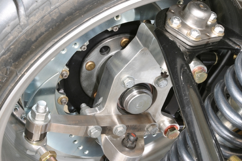
Yeah, as John says, the FEA is a dangerous weapon in inexperienced hands. It requires training and experience even for real mechanical engineers (which I'm not). This one slide was 1 of 30 different looks at the upright and steering arm. Glenn spent countless hours working on this in his spare time.
The resultant design change thickened the steering arm by 1/4" and added radiused bolt holes. You can see the difference in this picture of the actual upright/steering arm.
jp
 John Parsons
UnRivaled Rides -- Modern upgrades for your ride.
UnRivaled Rides recent project -- LS9-powered 69 Camaro
04-03-2005 #40
Registered User
- Join Date
- Jan 2004
- Location
- NW Suburbs, Chicago
- Posts
- 560
that looks sooooo incredibly incredible... wow...
and ive heard the same about FEA, I would NEVER trust what i do in FEA with my life. I just think it would be cool to check it out and see how it works. That would be something id leave to an engineer.
In the FEA, it looks like the steering arm is part of the upright, but obviously they are seperate parts. So there has to be a way to test assembly models like that with "clamping" forces of the bolts figured in as well. Or am i missing something?
Could i possibly get a copy of the power point? Im very interested and would like to see more of this.

 Reply With Quote


