


Results 41 to 60 of 146
Thread: chassis jig design
Hybrid View


-
01-21-2008 #1

 -Moderator/Sponsor-
- Join Date
- Jun 2001
- Location
- Orlando, FL
- Posts
- 10,604

Guys, this is a great discussion, even though the personal stuff is a bit on the edge. Two points from the mods:
1. The OP doesn't own the thread, but it is considered discourteous to change the subject.
2. It is a rare thread where a "spirited" discussion changes the minds of the participants. However, the technical data and interchange is often useful to other members of the board, even when the participants get a bit frustrated that others disagree with them.
Please watch the personal stuff, and carry on.
jpJohn Parsons
UnRivaled Rides -- Modern upgrades for your ride.
UnRivaled Rides recent project -- LS9-powered 69 Camaro
-
01-21-2008 #2 Registered User
- Join Date
- May 2002
- Location
- Northern California
- Posts
- 10,716
There is no hard feelings towards Mathius, he has his opinion and I agree with it and see his point. I have no idea why he is pushing it we can discuss that eles where.
But yes lets move on.
Jake, how mobile is that set up? Would weight be a hinderance? Would a flat section of floor be a necessity? And lastly...I don't see your Camaro on it...I hope that is atleast the frame for it. How is business?MrQuick ΜΟΛ'ΩΝ ΛΑΒ'Ε
01-21-2008 #3
Registered User
- Join Date
- Apr 2006
- Posts
- 1,027
vince, i need to get some wheels on it one of these days, however 2 floor jacks moves it pretty easy. its 18 ft 12 inch i beam, production made jig. you can shim the individual legs to level it however my shop is 3 yrs old and i had a good concrete guy pour the floor. Originally Posted by MrQuick
business is ok, alittle slow right now, doesn't help we have goten over 100 inches of snow already this winter and its -5 right now, lol
01-21-2008 #4 Registered User
- Join Date
- Nov 2007
- Location
- northern california
- Posts
- 388
finally picked up some new material to build one- I decided on some 6 inch i beams. We are gonna steal a buddies design to make it mobile by welding casters to the bottom of the i beam and then using acme thread that can pick up and level the table where ever it is. THat way you can use a lift to mount and dismount a car and then roll it over into a different area.
Scotts Speed and Custom
norcal1320.com
01-21-2008 #5
Registered User
- Join Date
- May 2002
- Location
- Northern California
- Posts
- 10,716
Cool Scot, make sure you post pictures of your monstrocity. Castors, perfect.
Art, that would be good. Might be abit over kill but sure. You can use 2 ton bottle jacks too. Might be cheaper.
Jake, tell me about it. Its like the next ice age...it was like 49 degree tody. burrrrrrrr LOL hope it picks up for you. everyone is slow.MrQuick ΜΟΛ'ΩΝ ΛΑΒ'Ε
01-21-2008 #6
Registered User
- Join Date
- Nov 2007
- Location
- northern california
- Posts
- 388
where in norcal are you? Im in discovery bay and the shops in livermore
Scotts Speed and Custom
norcal1320.com
02-24-2008 #7 Registered User
- Join Date
- Dec 2007
- Location
- Simi Valley, CA
- Posts
- 16
Jig Pic
heres a quick shot of mine.

02-28-2008 #8 Registered User
- Join Date
- May 2007
- Posts
- 249
figured I would ask here instead of starting a new thread, I going to be building a one time table for my project, and planned to use 4x4x1/8" or should I use something thicker? Plan was about 6 legs, 4'x16' 5 crossmembers and adjustable rubber feet to level it off. Would 1/8" be substantial enough? I won't be building my whole truck on this, just jigging the frame while I fabricate it.
02-28-2008 #9
Registered User
- Join Date
- May 2007
- Posts
- 249
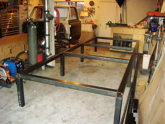
for example (not mine) just where I got the idea, from there I would put the stock frame on it, jig everything up then pull that frame and build the tube chassis. Just don't want to use 1/8" if people are going to think it's way to thin, just trying to do what's best for a small fortune since it's a one time table, plus I don't have anywhere to store it once I'm done with it.
02-28-2008 #10
Registered User
- Join Date
- Jun 2005
- Posts
- 543
Just read something somewhere (maybe PHR?) about Project X, the 57 Chevy GM is building. They had a chassis jig that I thought was very unique. The jig covered the whole floor, and had tracks and you could attach different fixtures within the tracks and move them around. The track held everything in place, but the point was, you could move the fixtures around to wherever you needed them.
There was a name for the type of jig, but I can't recall. Maybe you could build a smaller scale version if you could get a good look of how the tracks work?
Try a search for Project X. Might help.
Mathius
03-01-2008 #11
Registered User
- Join Date
- Dec 2007
- Location
- Simi Valley, CA
- Posts
- 16
heres another one
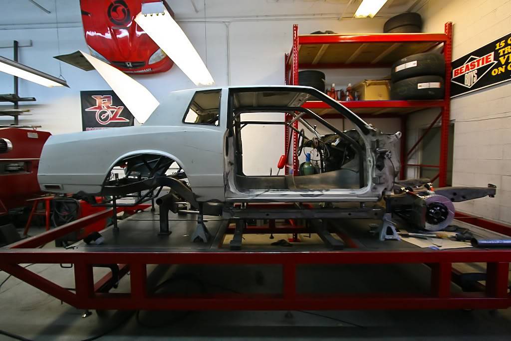 Nick Miserendino
Used to be known as redzone001
03-22-2008 #12 Registered User
- Join Date
- Apr 2001
- Location
- Rockford Illinois
- Posts
- 3,949
I just saw this thread for the first time and can say that the only important factor is that everything you measure off of or level up to is in the same plane.
I made my own jig out of 2 x 3 rectangular tubing and just used a welded nut and some bolt to level with. Yes I had to check it from time to time to make sure it was level because my floor would shift but it was more than accurate enough as long as I used the same reference points to level back to.
On another note I read an article years back in Car Craft I think that showed how to do a tube chassis and suspension install that just used a wire strung through the car at the center and all measurements started from there. It worked well and it kept it all in the same plane even if you were to have it on a rotisserie or stand it on end.
I also used a laser level for ceilings when I put my quarters on because I could measure up to the red line where it was impossible to measure from the fixture below. This made it very easy to do and you could do it with shims and a tape measure to level the car to start with and you can recheck everytime you start in about 5 minutes. I actually could have done the whole car that way if I would have wanted to. You just can't rely on a bubble level to install things if you are not level to the ground/world.
Hope this gives others a differnet perspective of some less expensive but more time consuming ways to accomplish the same thing. A good laser level can be bought for about $200 or rented from any rental place. Just ask for a drop ceiling laser and you will get the right tool for the job. Sears has a few that are even less expensive now that will also do the job well.
You can go to my cars site and see the basic fixture in some pics. The nice thing was that I could permanently weld my supports in and know that they didn't move. Now I have the extra tubing to build something else someday if I want and it doesn't take up space since it could be unpinned ( dowels so it would be stable) unbolted and stored away.
Goodluck and have patience
03-22-2008 #13 Registered User
- Join Date
- Jul 2005
- Location
- Eastern Virginia
- Posts
- 3,963
Hey Nick,
Got any more pics of the Monte on the table?Scot
86 Monte SS

03-28-2008 #14
Registered User
- Join Date
- Dec 2007
- Location
- Simi Valley, CA
- Posts
- 16
heres a few tell me whatcha think. Originally Posted by Samckitt
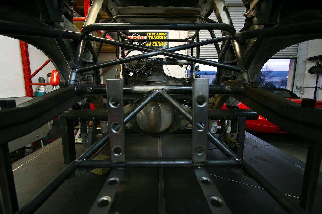
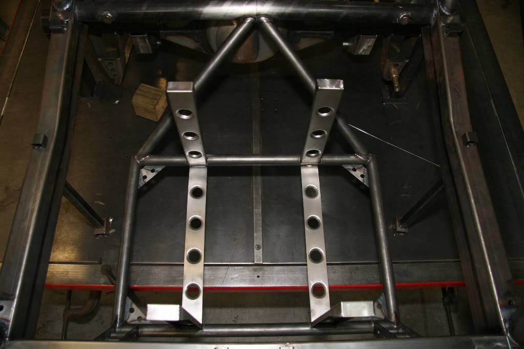
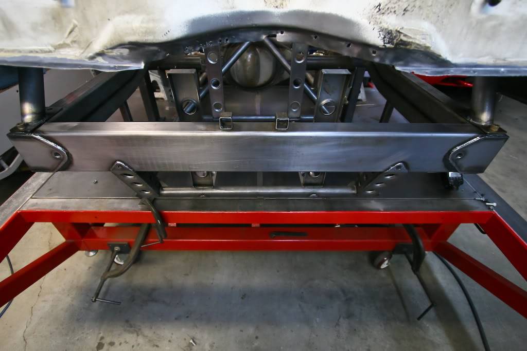 Nick Miserendino
Used to be known as redzone001
04-06-2008 #15 Registered User
- Join Date
- Nov 2005
- Location
- Motorcity, Canada
- Posts
- 292
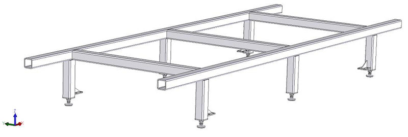
I just noticed this thread - what a coincidnce as I started build one for myself over the weekend. The goal here was to build something I could use in my garage, and something that could be built on a budget. I ended up making my own since it was clear it would be very expensive to purchase one complete. Since myself and a friend are building identical cars, and both have modern suspensions, this was the best way to make sure everything is in the correct place. This will also make car #2 much easier to set up quickly.
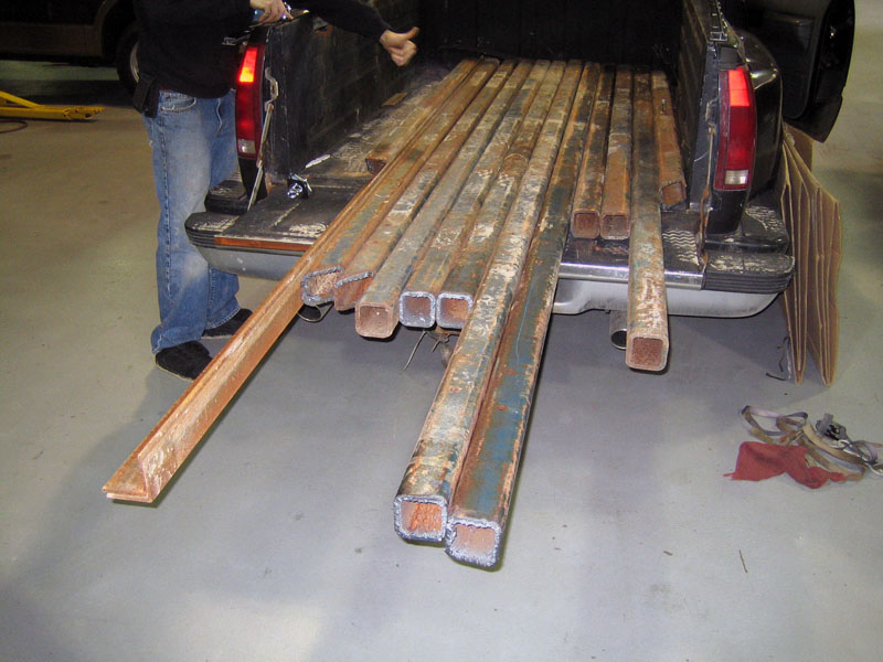
After looking at a couple of other designs out there, this is what we came up with. After looking for some steel, and realizing this would not be cheap to make, a wanted add was placed on Craiglist for steel (this past Thursday). On Friday we received a call from someone who had just taken down a billboard and was looking to sell the material (used of course). Saturday morning the steel was loaded up and in our possesion. The best part here is the budget. The only thing required now was time.
Cost:
~100ft 3"x3"x1/4" steel: $100 (Leftover steel will likely be sold to recover some cost)
Leveling feet for base of legs 5/8x11 & nuts for legs: $70
Paint and misc shop supplies: $35
Total cost: $205
Here is the initial concept in CAD:
Saturday morning after picking up steel.
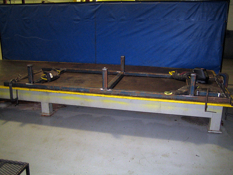
Sunday just before calling it quits (helps to have access to a surface plate to make sure our version is perfectly flat):
I have not really posted much online as I have not really done much actual fabrication on the car to be able to show major results. I will be posting more often once things get up and running. Now that I almost have the chassis jig completed, things will start falling into place. Most of the time to date has been in collcting parts.
04-07-2008 #16 -Moderator-
- Join Date
- Apr 2001
- Location
- Central CA USA
- Posts
- 6,114
SVTforme, Welcome to our forum! Hope to hear lots more from you.
I have no jig table and haven't really worked on a chassis on one, I've built lots of farm equipment on the floor though! But before taking that jig home, I'd weld some triangulating braces out of smaller tube to hold it flat. A better triangulation would be looking at it upside down in the photo, I'd run a framework parallel to the frame around the top of the legs sticking up forming a box, then add at least one diagonal brace per "box" section.
I would have made it slightly taller in case I needed to get underneath, plus with bracing, you will lose even more room. I wouldn't make it wider than the average car frame rail width, then use cut pieces of tube clamped across the jig to support the chassis or body.
David
Here's a link showing a jig table: http://www.circletrack.com/techartic...ech/index.htmlLast edited by David Pozzi; 04-07-2008 at 09:30 AM.
David Pozzi http://www.pozziracing.com67 Camaro RS that will be faster than anything Mary owns.
04-07-2008 #17
Registered User
- Join Date
- Nov 2005
- Location
- Motorcity, Canada
- Posts
- 292
Thanks for the input - I really appreciate it!
The design of this was based on the smaller version of the one you are referring to (Uni-Jig) as shown here. http://www.unijig.com/ . Is the extra bracing for stiffness to prevent the structure from parallelograming? What you mentioned will definitely stiffen up the structure, I am just trying to determine how much is enough.
The overall height of it was set to around 18", which should give plenty of room to get under the car to work on it (hopefully).
04-08-2008 #18
-Moderator-
- Join Date
- Apr 2001
- Location
- Central CA USA
- Posts
- 6,114
The one in your link appears to have large rectangular main tubes which are more rigid. My worry is the smaller tube (2" square?) you are using may not stay level when on the floor. We bent a similar sized tube just by welding a bunch of brackets on one side. The brackets were about 6" apart but the tube was heavy wall 2X3 tube and you could see a definite bow in it. Just welding on the legs can distort the tube and it won't show up until you release it from being clamped, it will spring back.
The "Y" shaped braces shown below are a nice addition. Personally I"d do something similar but minimize welding area and heat to reduce the of smaller material and only tacked on to the sides of the legs and main tube. Running a brace along the floor connecting the legs (left to right in the photo) would also help along with diagonal braces, but reduce access room underneath. 18" height sounds pretty good. The legs need some kind of height adjustment or you will need to shim them to adjust to the floor.
I altered the photo to show two ideas.
black lines running left/right along the floor are braces you could add to the legs, this forms a "box" section along with the legs and top rail.
1.Then the diagonal line on the right breaks the box into two triangles, this is much stronger and stiffer. Add another on the left side as a mirror image - have it going up and out to the left from the center leg, this forms a truss of sorts, quite strong/stiff.
2.The alternate for more access room would be on the left, two diagonals, three triangles, I kinda like this one the best. The braces could be 1 1/4" square or round tube.
IF the legs are bolted to the floor, then they are constrained from moving and the whole structure is much more rigid, the original frame seems to be intended for that method of installation. What I'm saying is, if you are not going to bolt it to the floor, then more bracing is going to help a lot. I'm not too worried about diagonal bracing when looking down from above, but some diagonal pieces of tube or rod would help if it seemed to be needed. If you do the braces I drew in, then you don't need the braces they are using.
Last edited by David Pozzi; 04-08-2008 at 10:06 PM.
David Pozzi http://www.pozziracing.com67 Camaro RS that will be faster than anything Mary owns.
04-09-2008 #19
Registered User
- Join Date
- Apr 2001
- Location
- Rockford Illinois
- Posts
- 3,949
I didn't have a lot of room at the time I built mine and I decided to make my jig a bolt together design and used dowels to locate the braces. It was nice to be able to remove the braces once some of the tacking was done to make more room to get comfortable. I weld a lot better when I can get comfortable.
$200 is a great deal for that much steel, that is what I paid for lighter gauge tubing a long time ago before the new increases went wild.
I did not bolt mine to the floor and had to relevel everytime I did something critical but it would only take about 5 minutes to recheck once the routine was down. You do not want to bolt it to the floor unless you have a slab of concrete that won't move, mine changed with the seasons as the foundation expanded and contracted. I also had a crack in the floor that would let me know when it was moving.
I also made mine bolt together so that it could be assembled square and not worry about distortion from welding on it. It also makes it more universal. I bolted to my suspension mounting points which are not the same for another car if you want to reuse the jig and made the supports with a specificaly welded bolt in brace. It wasn't very long working on the frame and I could have put it on jackstands sooner but it was supported at points that allowed a lot of the work to be done before I had to take it off of the jig.
One other thing I did was make the leveling bolts spaced every 2 ft, but my base was right at floor level which made it a bit harder but I did not have any way to raise the car more than 22" anyway without hitting the support beam in the garage. I also had no way to get it out from under the car once I was done and unbolting it made it as easy as putting the car on jackstands and removing the jig from under the car piece by piece. this is an important thing to think about, you don't have a forklift or hoist to move a car around. Do you?
There is a lot to think about before you get carried away and the biggest thing is to keep it simple and just check it more often if you have to. Remember LEVEL is LEVEL no matter if it cost $200 or $20,000 and the car will never know the difference. And it has to just work for you since you won't make a living with it !
Goodluck and I hope some of my obstacles that I had to work around help you design what is best for you.
04-09-2008 #20
Registered User
- Join Date
- Aug 2003
- Location
- Southern Louisiana
- Posts
- 377
My problem was I needed a body cart, a surface plate, and a chassis jig, but only have room for one. So I made one that I could do everything on. I made mine out of 2x2x.125"wall. Topped it with 3/8"plate. It's 10'x6' and I wish I had made it longer. It has a line down the middle I pull all my measurements from. When I bought the 10x6 plate, it had the outside edges slightly rolled from the milling process as all plate does. I cut the plate down the middle, flipped the halves around, and when butted back together, had a nice straight line down the middle. Beat having to have it machined in.
I was going to put screwjacks every couple feet, but found it didn't need it. Just ended up with them at the four corners, and in the center. And even the center one I don't really use. If I crank on the center jack the whole thing lifts. And it's flat and true. I think I went overkill on the 2x2 frame, but it does what it's made to do very well. Total weight came in around 2500lbs. I think the plate is just under 1000lbs
I mounted the gutted shell to the table (C/L of body over C/L of table, plumb bobs for square, set ride height,etc.) and did my layout of the bottom part of the chassis on the plate. This works out great because if I needed a measurement from the body, it was just above when I'm doing the layout. Welding isn't a problem because the body is high enough not to be in the way.
Here's a pic of where I'm at now. The lowest part of the chassis is set at ride height with the body. I'm doing the rest of the spaceframe out of round tube, just tacking it. When it's time to weld everything I'll lock it back down to the plate.
I've been really happy with it so far. With the castor's, I think I have around $1000-$1100 into it. I do think if I was putting a lot of weight on it, I would need to add more screwjacks.
Kevin

 Reply With Quote


