

Results 161 to 180 of 261
Thread: First-Gen S10 Corner Carver
-
05-24-2013 #161

 Registered User
- Join Date
- Sep 2006
- Location
- New York, NY
- Posts
- 458

My friend Karlo installed 4 corner Walbro pickups in the fuel tank to prevent fuel starvation under cornering when fuel levels are less than full.


Anybody have tech on whether installing fuel foam or other baffling like this (http://www.pirate4x4.com/forum/14907722-post1.html) is worth the trouble? The 4 corner pickups should eliminate any fuel delivery issues so the additional foam or baffling would only help reduce weight transfer from fuel slosh. The downside is foam breaks down and either solution would require a rather expensive tube-style fuel level sender replacement for the float type sender currently installed.
-
05-25-2013 #162
Registered User
- Join Date
- Aug 2007
- Location
- Albemarle, NC
- Posts
- 1,151
so what all dod you get to make the pickup system? i want to build one, and youre the first guy ive seen actually do it. id rather copy what you used and tweak it for my tank than reinvent the wheel...
and from what im thinking, the foam will not be necessary with the 4 corner pickup. i cant see weight changing enough to make a difference without it, and fuel sloch problems are almost eliminated with the 4 corner system.
michaelMichael Crawford
1970 plymouth Duster back under construction:
https://www.pro-touring.com/showthre...uring-makeover
1987 GMC S15 https://www.pro-touring.com/showthre...ct-drivabeater
05-26-2013 #163 Registered User
- Join Date
- Nov 2006
- Location
- Ma.
- Posts
- 5,569
Nice job.
Wayne
Car FINALLY home !!!!!! lol
Project FNQUIK https://www.pro-touring.com/showthre...ghlight=FNQUIK
05-26-2013 #164
Registered User
- Join Date
- Sep 2006
- Location
- New York, NY
- Posts
- 458
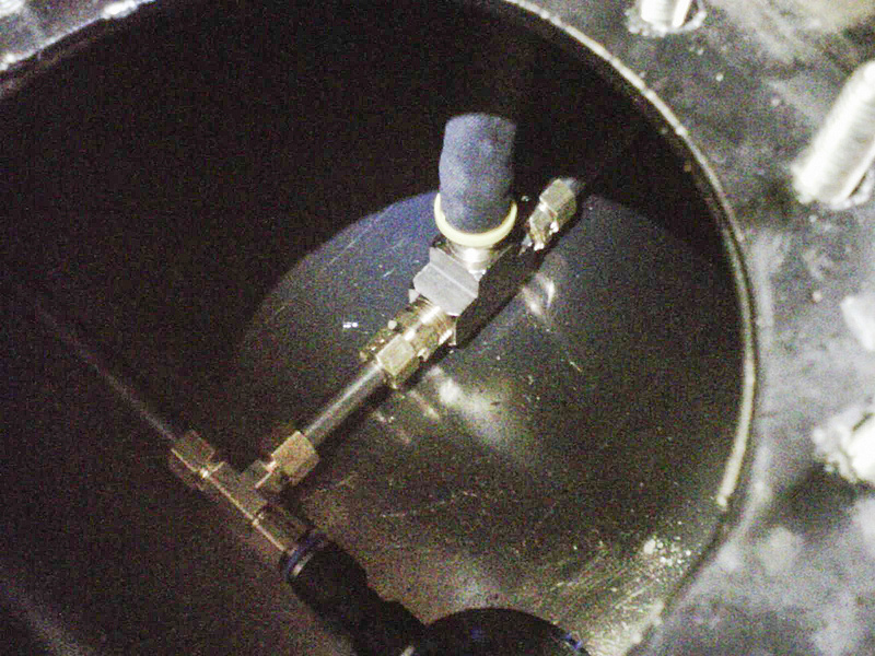
There are 3 walbro MP-12 pickups and 1 MP-13 pickup. You'll need an access hole (the fill neck flange on most tanks is big enough) and will need to assemble the tubes together inside the tank. Originally Posted by dusterbd13

Here is the description from the vendor:
They make kits for all the RCI tanks but I am sure you could tell them the dimensions of your tank and the pickup location and have them send you a custom kit. They aren't cheap though and if you are starting from scratch I would fully price out a fuel safe or ATL cell since that will have a bladder for additional safety. This route is still cheaper but not by as much if you start adding foam and a tube-style sender.These Walbro in-tank pickups have a 70 micron mesh that serve as a pre-filter. When submerged, the pickups flow fuel through as normal. If there is a shortage of fuel where the pickup is, they shut preventing air from entering the fuel system. Generally they are plumbed in systems of 3 or 4 pickups, usually one in each corner depending on the size of the fuel cell. Tall skinny fuel cells such as RCIs 2161a can get away with just two pickups. If there is any chance that the vehicle these are installed in might run completely empty, Walbro recommends at least one pickup in the system to have a bleed hole. MP-13s and MP-15s have a bleed hole in them, MP-12, MP-14, and MP-16 do not.
MP-12s and MP-13s are dead end style pickups meaning there is a single 5/16 fitting on the top. MP-14s, 15s, and 16s, are flow through style and are meant to be installed inline in the system. The MP-16s are a 90* flow through.
These pickups are approximately 3 inches in diameter and 2 inches tall.
I'm still working out how to get the fuel to the carb. I'm considering a Bosch 044 external pump to an Aeromotive 13204 regulator (bypass). Anybody used the Bosch pump before or have other recommendations? I am thinking of doing an EFI pump and a return line so that it is easier to go EFI in the future. The thinking behind doing an oem style pump is that they should be quiet and reliable while being considerably cheaper than something like the Aeromotive A1000.
05-27-2013 #165
Registered User
- Join Date
- Aug 2007
- Location
- Albemarle, NC
- Posts
- 1,151
so what did you use for the brass and t-fittings? inverted flare fittings and brass usinions from gas water heaters? im not starting from scratch. im starting with a stock tank that im converting to EFI. but its a used stock tank.
actually, iull be doing this twice. once with the 70 duster, once with the 64 el camino.Michael Crawford
1970 plymouth Duster back under construction:
https://www.pro-touring.com/showthre...uring-makeover
1987 GMC S15 https://www.pro-touring.com/showthre...ct-drivabeater
07-16-2013 #166
Registered User
- Join Date
- Sep 2006
- Location
- New York, NY
- Posts
- 458
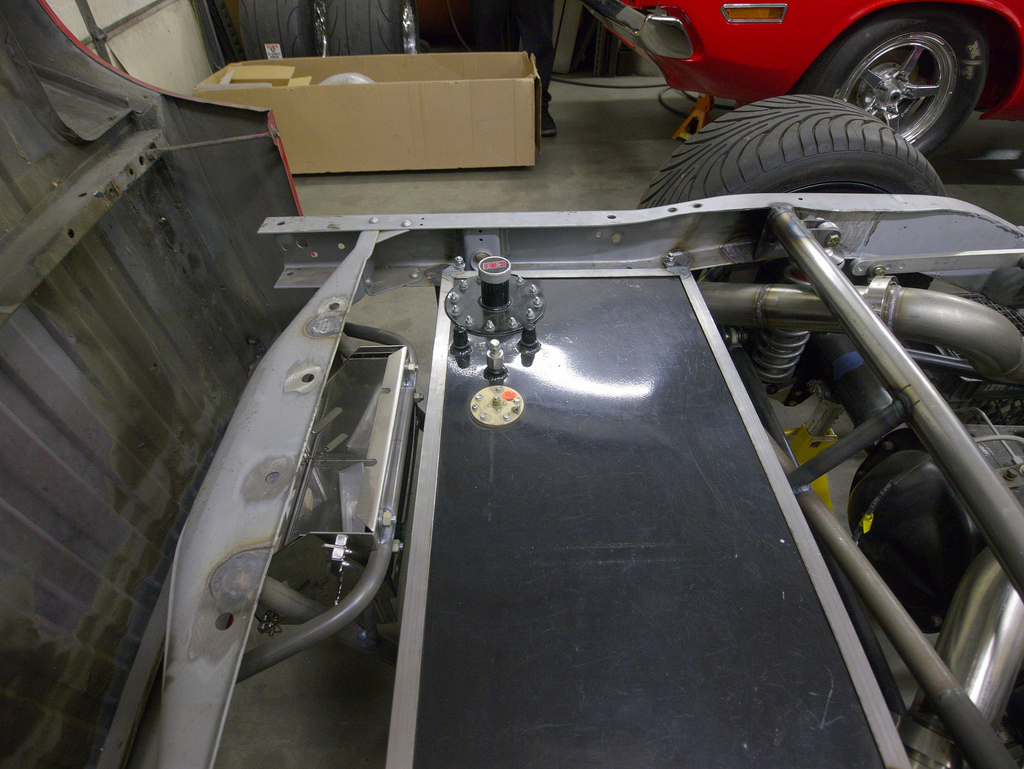
New center structure:
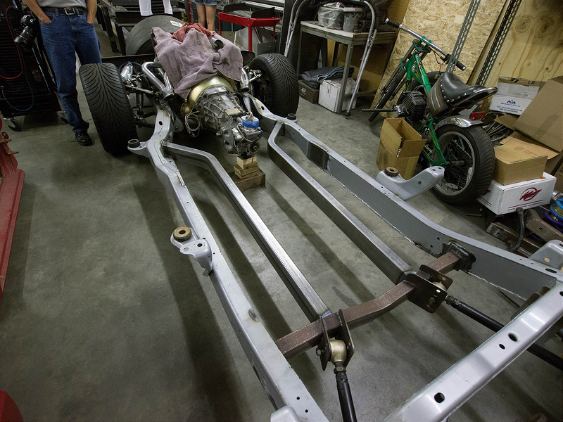
Clearance for straighter exhaust path
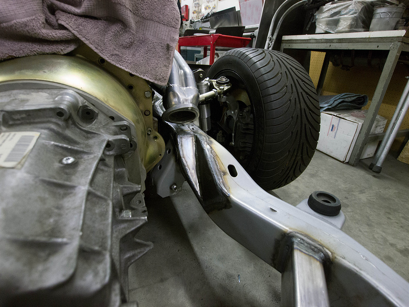
New fuel tank mount (straps to be added above):
New rear coilover crossmember
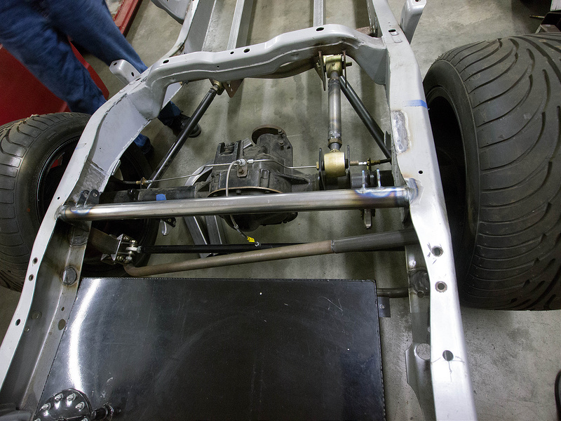
Front coilover mount with quad adjustable varishocks:

07-16-2013 #167
Registered User
- Join Date
- Jul 2012
- Location
- Iowa
- Posts
- 399
Im so glad to see how you did your frame. That is exactly how im setting up the front half of the frame and I wasnt sure if that was a smart way to do it or not. A few more cross braces will be in there but your not done with your frame yet either.
Miles Boyer
The car hobby is dangerous,if the speed doesn't kill you, the cost of parts will.
91 V8 S10
88 Cutlass Pro-Tour
97 Chevy lifted Z-71
96 Corvette
07-16-2013 #168 Registered User
- Join Date
- Nov 2008
- Location
- NC
- Posts
- 583
Wow, that looks great, awesome job.
Keep up the good work man.
07-27-2013 #169
Registered User
- Join Date
- Jul 2012
- Location
- Iowa
- Posts
- 399
I was looking at my frame this weekend and Im wondering what are you going to do for a E-brake? Id like to keep the stock set up but without getting over fancy I dont see how that would work. I think Ill find a hand brake to put on the trans tunnel and see how that works but I was wondering what your thoughts on that are.
Miles Boyer
The car hobby is dangerous,if the speed doesn't kill you, the cost of parts will.
91 V8 S10
88 Cutlass Pro-Tour
97 Chevy lifted Z-71
96 Corvette
07-28-2013 #170
Registered User
- Join Date
- Sep 2006
- Location
- New York, NY
- Posts
- 458
I will probably use the lokar trans tunnel mounted one Originally Posted by silvermonte
09-17-2013 #171
Registered User
- Join Date
- Sep 2006
- Location
- New York, NY
- Posts
- 458
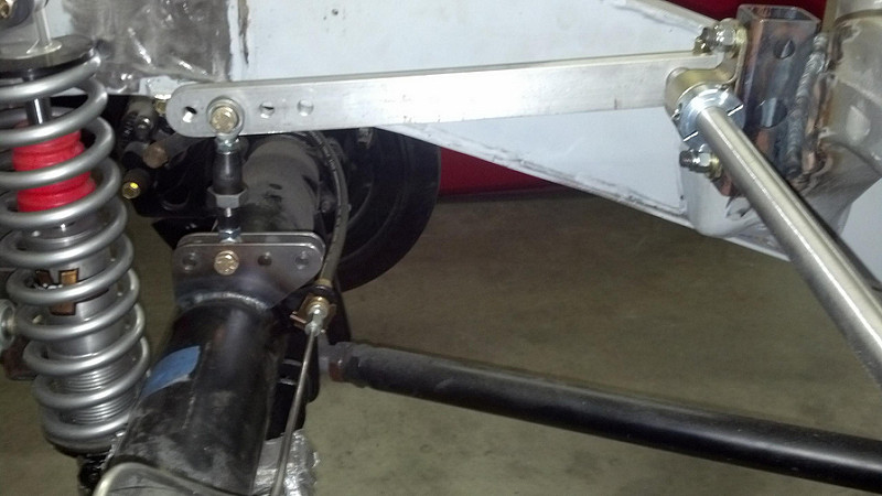
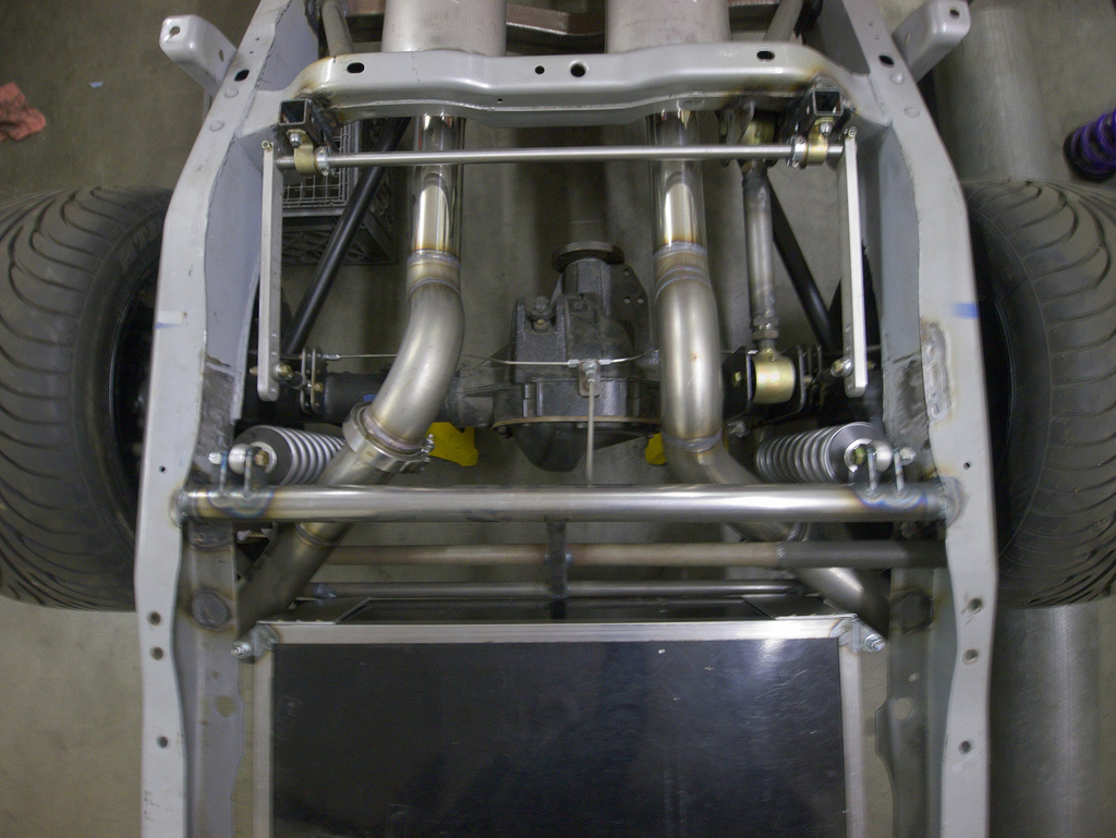
Rear anti-roll bar with 3 inches of adjustment
10-08-2013 #172 Starting The Transformation
- Join Date
- Sep 2008
- Location
- Sacramento, CA
- Posts
- 410
Hey Jerome, I just found your thread. Glad to see those Q4R VariShocks mocked up. Can't wait to see what you do with this truck, looks like it's gonna be awesome!
Originally Posted by jerome
Carl Ogren - Sales and Tech
Email us to get your Chassisworks/TCP Equipped vehicle featured on Facebook!
Chris Alston's Chassisworks - Phone: 888.388.0297 ext 247
Chassisworks - TCP - Varishock - Component Drive Systems - KP Components
10-08-2013 #173 Registered User
- Join Date
- Apr 2005
- Location
- Chicago
- Posts
- 2,788
Man I look at this thread and I really miss my truck. Hurry Up I need to see this thing on the road.
marty-mj
GarageScene.net High Speed Welding KDHotrods RecoveryRoomInteriors WegnerAutomotive Autometer Ride-Tech
10-09-2013 #174 New to Pro-Touring
- Join Date
- Sep 2013
- Posts
- 31
badass truck. love what your setting it up for. keep updated please.
10-10-2013 #175
Registered User
- Join Date
- Sep 2006
- Location
- New York, NY
- Posts
- 458
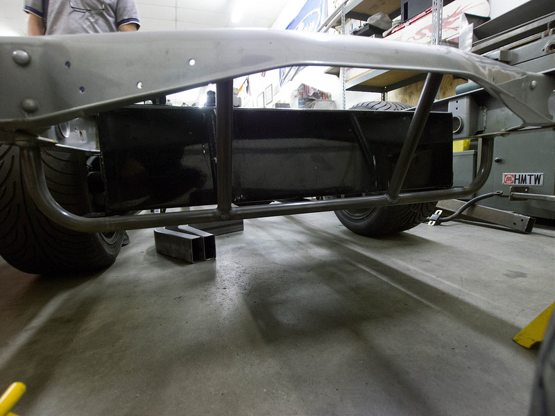
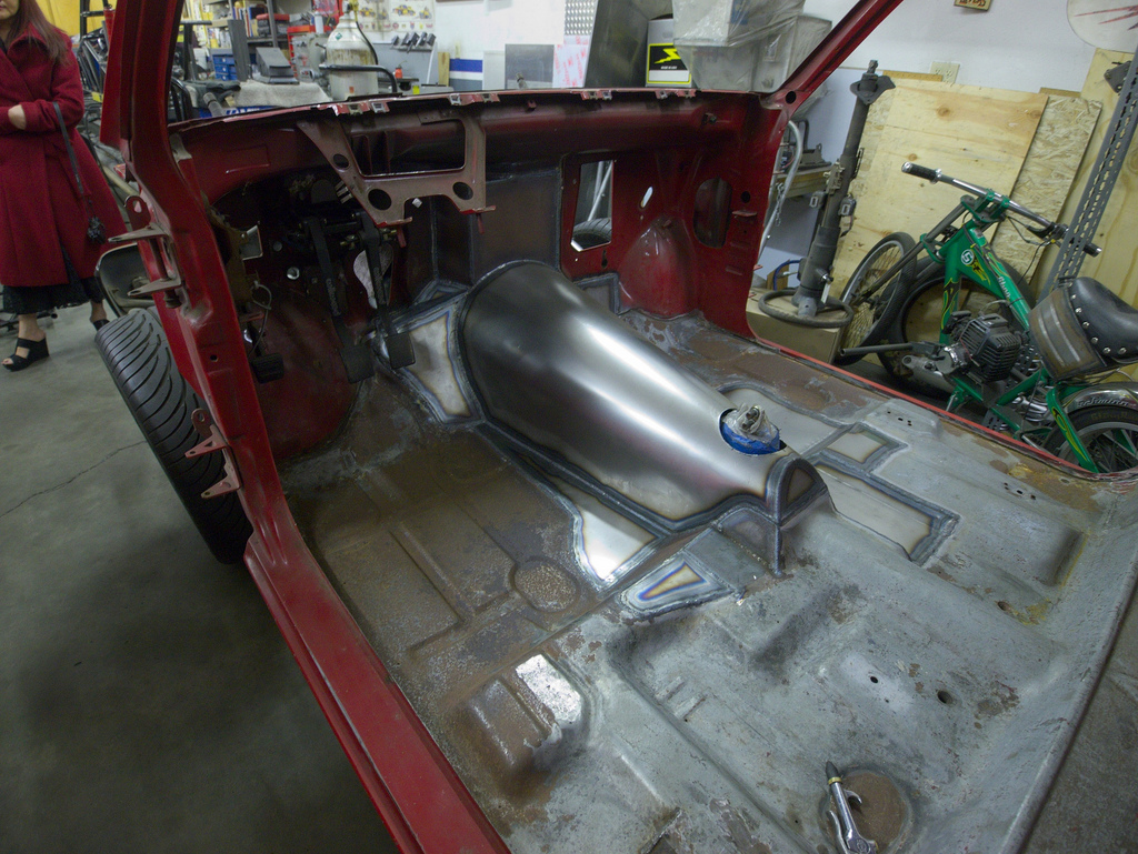
Thanks for the comments guys. Looking forward to some faster progress now that racing season is over for Randy (my builder). Here is a pic of the fuel tank hold-down. You can also kind of see the exhaust snaking around it, unfortunately no pictures of it yet.

10-10-2013 #176
Registered User
- Join Date
- Apr 2005
- Location
- Chicago
- Posts
- 2,788
Keep em coming
marty-mj
GarageScene.net High Speed Welding KDHotrods RecoveryRoomInteriors WegnerAutomotive Autometer Ride-Tech
10-10-2013 #177
Registered User
- Join Date
- Sep 2006
- Location
- New York, NY
- Posts
- 458
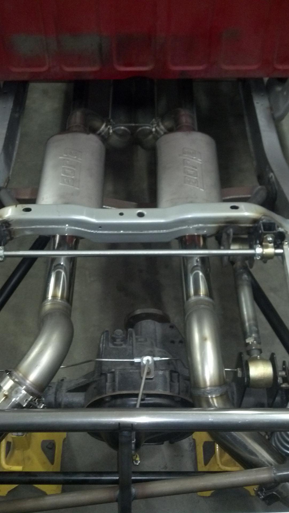
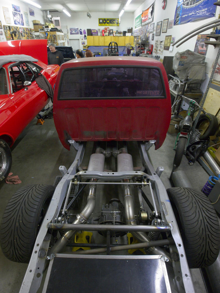
Just got this picture of the exhaust from Randy. If you look at the top of the picture under the cab, you can see a pressure wave termination box. I've put it 40" behind the collectors (as determined by Pipemax simulation). It's an attempt to have a tuned secondary length that maximizes power by taking advantage of exhaust pressure wave reflections to scavenge exhaust. The concept is that the exhaust "thinks" it is entering free air when it enters the big chamber. This is the theoretical end of the secondary and everything after that does not affect the pressure wave reflection characteristics anymore. Mufflers are Borla XR-1's. Originally Posted by syborg tt
You can read more about pressure wave theory here. It may not be worth much horsepower, but I've decided to build it in after reading up alot on it. Unclear how it will change the exhaust sound, but I'm guessing it will sound similar to an x-pipe exhaust. Happy to explain more if you guys are interested.
http://www.popularhotrodding.com/eng...h/viewall.html
10-11-2013 #178
Registered User
- Join Date
- Aug 2013
- Posts
- 7
 I would definitely utilize the baffles from Wayne at Alltech. They are absolutely worth it, a half-full tank of fuel hammering back and forth is not good for weight distribution nor is it safe. Stay away from foam at all costs!! Wayne's baffles do the job and will not break down overtime. My buddy has had them in service in his Ultra4 car for almost a year now with zero degradation. Originally Posted by jerome
10-18-2013 #179
Registered User
- Join Date
- Sep 2006
- Location
- New York, NY
- Posts
- 458
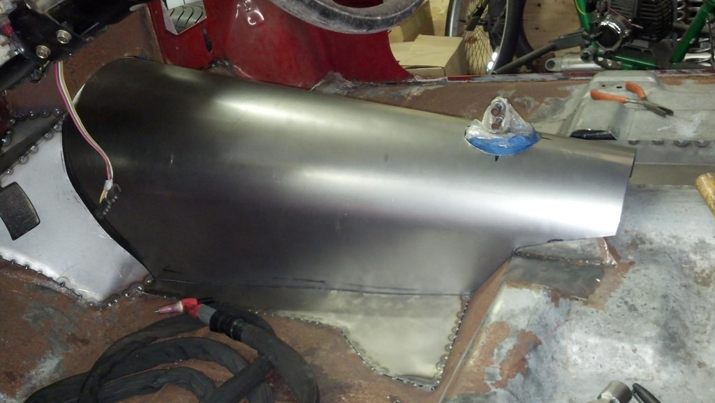
Transmission tunnel taking shape:
01-03-2014 #180
Registered User
- Join Date
- Sep 2006
- Location
- New York, NY
- Posts
- 458
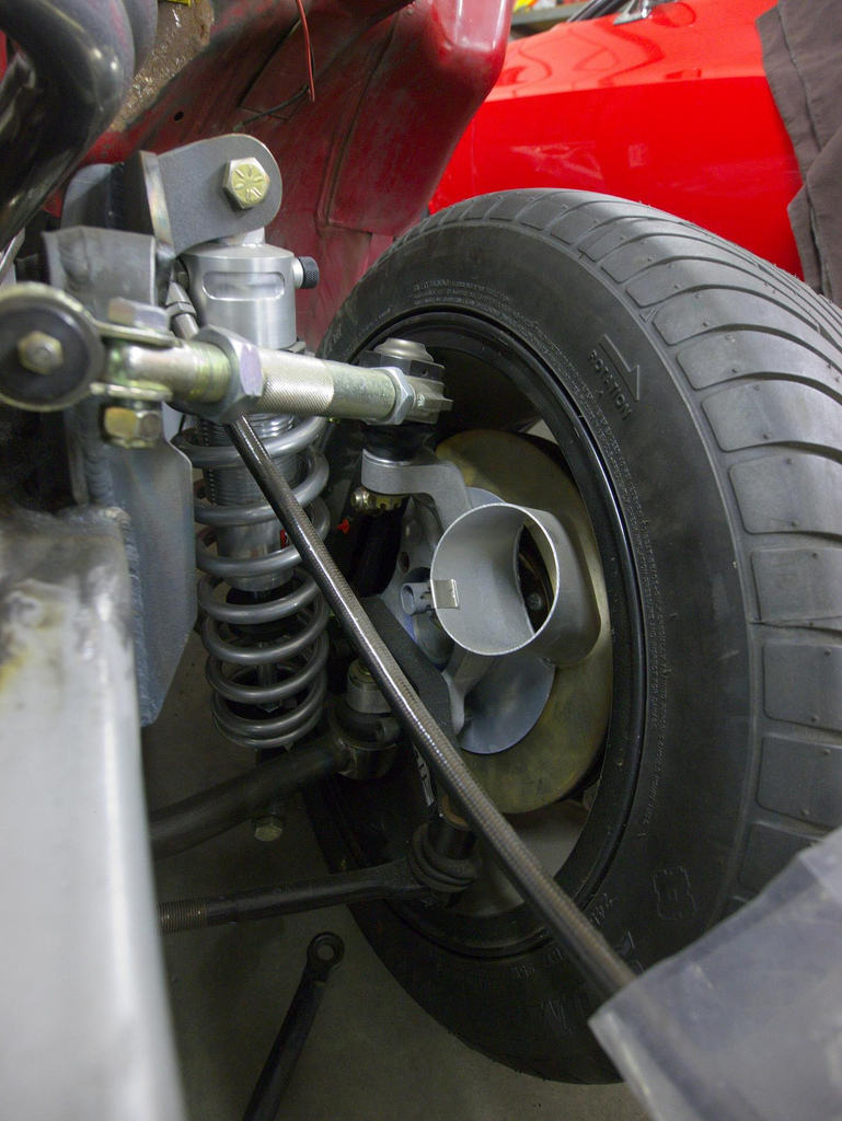
Brake cooling duct plate mounted on the spindle, replacing the ABS speed sensor mount plate.

Went to Wilwood SL4 (4 piston) calipers instead of stock C5 calipers for ease and cost of pad replacement. Staying with C5 rotors for low cost of replacement.
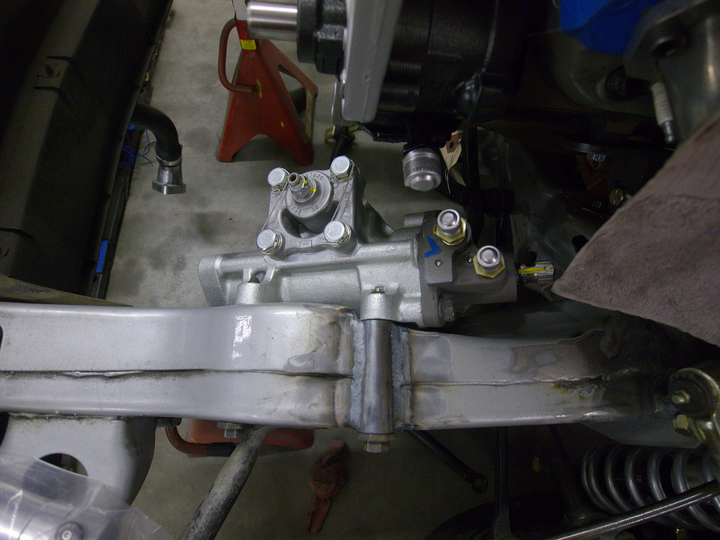
New 670 steering box from Lee Mfg mounted. S10 steering boxes only have 3 bolts, so a sleeve was added to the frame to accomodate the 4th bolt on the 670 boxes. Above it you can see the steering pump that was converted to an external reservoir and matched to the box. This is a 12.7:1 box, it is 6.5lbs lighter and it has some rack and pinion technology in the valve that is supposed to make it feel much more like a modern rack than the steering boxes that came in older muscle cars. I don't fully understand the tech, but these get positive reviews across the board.
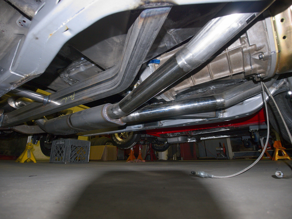
Here is a shot of the pressure wave termination box. It is a hollow chamber that is 16X the volume of a cylinder. It has 3 internal ribs that should keep it from getting blown apart by the exhaust pulses and resulting vibration. 16X is the general guideline on minimum volume for it to be effective at stopping the exhaust pressure wave. The idea is that it gives you a secondary length that is unaffected by anything after the box. So you could put whatever muffler or tailpipe length as long as it is capable of sufficient flow to support the engine. The actual secondary length was approximately 40", which is what Pipemax spit out as optimal. I have no way of verifying if all of this works, but I figure if I am going to build an exhaust system, I might as well build one that is theoretically optimal (setting aside the shorty headers).
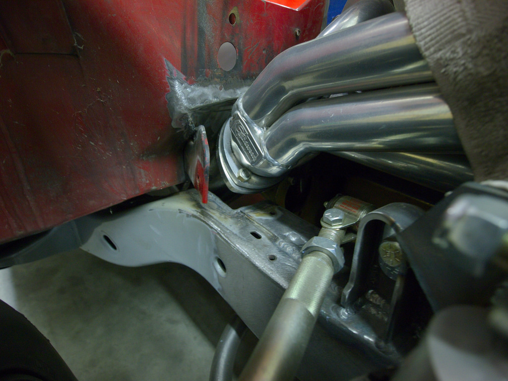
Clearance needed in cab and frame to allow the headers to work
You can see the drop down battery box on the left of the picture. It is very far back, but it will be protected somewhat by the trailer hitch. Trading better F/R weight distribution for less responsive polar moment of inertia. Fuel tank has a round tube cage underneath it and straps and hold down bolts securing it from above. It will only be serviceable by removing the bed (6 bolts and 2 people).
Exhaust routing is very tight between the corners of the fuel tank and the tires. You can also see the roll bar in this shot. There are 3" of adjustment along the arms and rearend brackets to allow for rate change.
You can see the two Borla XR-1 mufflers in this shot. These are the multicore ones which are supposed to be a bit quieter than the sportsman models. I am hoping these will be quiet enough for daily driving, but if they are not, I am trying to figure out a way to use an electric exhaust cutout valve in-line to try to quiet it down. I would put one in-line on the driver's side exhaust after the termination box. When closed, it would force all the exhaust through the passenger side muffler. I don't know enough about the physics of sound to know whether this would actually make it quieter, but it will not be hard to plug one side to test this out once the engine is running.
Transmission tunnel welded up
The driveshaft has not been ordered yet because the current driveline angles are not going to work unless I use a CV shaft joint at the front of the driveshaft. The engine is currently at 5 degrees down front to back and with the pinion at 3 degrees up towards the front, the driveshaft would be parallel to the ground. This means 5 degrees of working angle at the front and 3 at the back of the shaft. The recommended range is 1 - 3 degrees. Unfortunately, the transmission tunnel won't allow the back of the transmission to come up any, so the engine mounts will have to be reworked to come down. I will shoot for 1 degree working angles at both front and back. Because of the length of the shaft (63" from output shaft to face of companion flange) and the 4:10 gears, to get a reasonable top speed (above 100mph), I'll need to go with an expensive carbon fiber shaft. The other alternative is a 2 piece shaft, but the potential for added vibration, the cost of fabricating a carrier bearing crossmember and the extra weight make the carbon fiber shaft a more attractive alternative.
Next step is to get the roll bar installed. I have gone back and forth on roll bar mounting. It is tricky because it will need to go through the cab where the body mount bushing is:

What I have decided is that I will have the roll bar tube pierce the top side of the floor and extend to the underside of the "pedestal" that rests on the body mount bushing. I will weld a plate with 4 perimeter bolt holes to the bottom of the body mount pedestal. The roll bar will weld to the top side of this mounting plate. A custom mount will have to be made from the frame with a matching 4-bolt rectangular plate. The effect of this will be that the roll bar will be connected to the frame with 4 bolts at each corner. In a perfect world, I want to keep the body removeable and retain the body mount bushing. However, the compromise for a rigid roll bar mounting is increased vibration from not having a bushing.
2 Cobra Suzuka seats have been ordered and should be delivered in the next couple of weeks. I went with the wide width for comfort daily driving even though I am 5' 9", 150lbs. I ordered them in black vinyl for durability.
After the seats are installed, it is time for fuel system and brake plumbing before it all gets blown apart to paint/powdercoat the frame and get ready for final assembly.

 Reply With Quote


