


Results 61 to 80 of 97
-
10-27-2006 #61
 Registered User
- Join Date
- Jul 2006
- Location
- Chesapeake, VA
- Posts
- 677
I see your point. What if the structure closing the bottom of the tunnel has sturdy tabs on it so that it fits snugly up into the tunnel and cross-bolts horizontally as well as vertically?
-
11-14-2006 #62
Starting The Transformation
- Join Date
- Jun 2005
- Posts
- 379
Just got back from SEMA and an extended vacation in Aruba. Had a great time at both, but, I am happy to say, it is now time to get back to business. If we are going to get both of these cars ready for the Detroit Autorama, we are going to have to get our butt's in gear. :-)
In regard to the original subject of this thread, I just spent about an hour talking to Chris over at Maximum Motorsports. He told me that they did some before and after testing on Fox body sub-frame connectors.
And the results are....
Sub-frame connectors have little to no effect on improving torsional stability. They do help improve “beam” deflection of the frame rails, but do nothing to reduce torsional deflection or "twist".
There you go. Sub frame connectors will help stiffen up and help reduce "sag" or "bounce" in the beam direction, but do little, if anything, to reduce chassis twist.Bob
http://sn65.com/
11-14-2006 #63 -Moderator-
- Join Date
- Apr 2001
- Location
- Central CA USA
- Posts
- 6,114
 Thanks, It's as I suspected.
 Originally Posted by SN65
I remember the Herb Adams "Silverbird" Trans Am race car, - it had a long panel underneath that closed in the trans tunnel. I see Alston Chassisworks has an underbody brace system for first gen Camaros that is for torsional stiffening. Too bad we have to have things like driveshafts and exhaust systems underneath the car...
DavidDavid Pozzi http://www.pozziracing.com67 Camaro RS that will be faster than anything Mary owns.
11-17-2006 #64
Starting The Transformation
- Join Date
- Jun 2005
- Posts
- 379
New update at the site
http://sn65.com/Fire%20&%20Ice%20uni...nforcement.htm
Check out the fuel door we are currently evaluating.
With that said, it is time for the suspension gurus to chime in and help with the front end geometry.
Here are our issues....
We are going with a strut front suspension. We intend to use the early Mustang lower control arm and the front strut.
When we set the suspension at ride height, we have about 1" of suspension travel before the lower control arm buries itself into the frame rail.
Is this enough? I don't think so.
To gain more suspension travel we can modify the lower control arm and front strut or we can go with a 2" drop fox body spindle and strut.
If we alter the lower control arm assemblies by sectioning and "bending" we will end up with about a 1" rise from the control arm mounting position to the ball joint pivot point. If we go with the 2" drop spindle we will end up with about a 1" drop from the control arm pivot point to the ball joint pivot.
I am thinking that it will be better to go with the 2" drop. I can always relocate the control arm mounting point down a bit if the goal is to end up with a true horizontal plane from the inner pivot point to the center line of the ball joint.
Any input would be greatly appreciated.Bob
http://sn65.com/
11-17-2006 #65 Registered User
- Join Date
- Mar 2004
- Location
- Mid-Michigan
- Posts
- 2,764
Modifying the LCA is probably your best bet Bob. Leave the inner and outer pivot points where they are and build a new arm to connect the dots.
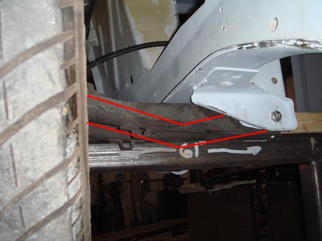
Dropping the inner pivot isn't a good idea because then you start getting into steering problems. Bumpsteer, ackerman, that kind of stuff. If you can build a new arm to hit the old points and clear your frame you will be heading in the right direction.
Figure out how much travel you have and then add about a 1/2" to that for clearance.
MarkMark:
"Bad Ast" Astro Van. Just because I did it... Doesn't mean it's possible...
This my Bad Ast thread...
https://www.pro-touring.com/showthre...roject-Faze-II
This is my Fotki album...
http://astroracer.fotki.com/
11-27-2006 #66
Starting The Transformation
- Join Date
- Jun 2005
- Posts
- 379
This weekend we finished up all the chassis mods. Just some grinding and sanding and we should be ready to drop her back on the frame rack for the final torsion test.
Here is a link to the latest photos.
http://sn65.com/Fire%20&%20Ice%20uni...nforcement.htm
It will be interesting to see what the final numbers come in at. I am guessing that we will have reduced torsional deflection by somewhere in the 80 to 90% range. Not to bad for a car without a cage.Bob
http://sn65.com/
11-27-2006 #67
Starting The Transformation
- Join Date
- Jun 2005
- Posts
- 379
Hummm....
We just performed our final torsional test and the numbers have not changed from the last test.
Hummmm.......
We are currently at 70% reduction in torsional deflection. I would have guessed that all the welding and the last few mods would have netted us some gain, but evidently not.
However....
We did cut the lips off the rear quarter panel / wheel opening in preparation for the fender flares. Right now, the quarter is not attached to the outer wheel housing. And, the quarter draws tight on the side under pressure and loosens up on the side under compression.
This must be throwing off the numbers. I guess we will have to weld the quarters back up before we can finish the test.
It is funny how little things can have profound effects.Bob
http://sn65.com/
11-29-2006 #68 Registered User
- Join Date
- Jul 2003
- Location
- Anaheim Hills, CA
- Posts
- 11,967
Would the subframe connectors (ala DSE) help more with torsional/twist rigidity more than ones that hang below the floor?
I would think that having them through the floor would help with body twist to some degree."A ship in port is safe, but that's not what ships are built for."
1968 Track Rat Camaro:
https://www.youtube.com/watch?v=SGHJ5c1yLIo&t=2s
1971 Chevelle Wagon with a few mods:
https://www.youtube.com/watch?v=WBVPR3sRgyU
11-29-2006 #69
Registered User
- Join Date
- Jul 2006
- Location
- Chesapeake, VA
- Posts
- 677
I think you'll find those wheel housings to be pretty important once you weld them back together and retest.
11-30-2006 #70
Starting The Transformation
- Join Date
- Jun 2005
- Posts
- 379
Originally Posted by Steve1968LS2
Originally Posted by Steve1968LS2
Hi Steve,
From what I have seen in our testing and from conversations with the engineers at Maximum Motorsports, I would have to say that all subframe connectors will help in regard to beam deflection, but none will have much impact on torsional deflection.
I would guess that the DSE items would be a step up from the hang below the floor variety, but without any comparative testing, it is difficult to say just how much of an improvement you would see in the real world.
I really like the subframe connector design by Maximum Motorsports. If you look at their design, they tie the middle of the SFC to the seat pans with a cross brace. This stiffens up the structure by reducing the unsupported length of the SFC by 50%.
It is interesting to me that no one publishes any test data on their structural modifications. Everyone and their brother (or sister) makes a subframe connector, but no one publishes any data on what the actual improvements may, or may not, be.
When dealing with a group of car fanatics who will pay thousands and thousands of dollars to improve performance in any way shape or form, you would think that testing and publishing the data on chassis modifications would be a no brainer. We pick just about every component in our cars car based on some kind of quantifiable performance improvement, but chassis mods are picked based on recommendations and "empirical" data.
Has anyone out there seen any type of published data on chassis modifications?Bob
http://sn65.com/
11-30-2006 #71 Registered User
- Join Date
- Jul 2001
- Location
- Calgary, AB
- Posts
- 1,826
 Would that not suggest that the DSE style SFC, which is welded to the floor along their entire perimeter, would provide superior support as there is no unsupported portion of the SFC? It seems to me that the benefit of the cross braced connector would be the actual cross brace itself being perpendicular to the SFC. Originally Posted by SN65
Just an observation
James
11-30-2006 #72
Registered User
- Join Date
- Jul 2003
- Location
- Anaheim Hills, CA
- Posts
- 11,967
I happen to be doing a story on installing a set of DSE SFCs.. I talked to Kyle yesterday and mentioned this thread. He said their test showed that their SFCs do help with torsional twist. He also said they will have data on this available soon. Originally Posted by reboot04
I let him know about this discussion, so hopefully he will chime in.
The cross brace deal is nice but hard to package with stock stuff like a driveshaft and exhaust. Most of us are not building race cars so how stiff do we need it?"A ship in port is safe, but that's not what ships are built for."
1968 Track Rat Camaro:
https://www.youtube.com/watch?v=SGHJ5c1yLIo&t=2s
1971 Chevelle Wagon with a few mods:
https://www.youtube.com/watch?v=WBVPR3sRgyU
11-30-2006 #73
Starting The Transformation
- Join Date
- Nov 2005
- Posts
- 180
If rollcage is tied into dse sfc,it will also aid in torsional deflection?
Camtender,Privateer by choice
Member of Hot Rod Power Tour Long Haul Gang 03'
Winner of the 2nd annual Pro-Touring.com Run Thru The Hills drag racing event sponsored by Musclerides.com 06'
2nd in class @ Big Bend Open Road Race 07' http://www.youtube.com/watch?v=Nti3UarUwzU
Record holder @ The Texas Mile 08' for 1st gen. camaros http://www.youtube.com/watch?v=lvEzlnnAB8I
http://www.youtube.com/watch?v=6L0sYaMnni4
12-01-2006 #74
Starting The Transformation
- Join Date
- Jun 2005
- Posts
- 379
What we are finding (on the early Mustang) is that the structure rear of the drivers seat is much more stable than the area in front of it.
The above revalation probably comes as no surprise to anybody.
I question how much any SFC will help with torsional stability or "twist". They will help quite a bit with beam deflection. It will be interesting to see, and I look forward to, their before and after test results.Bob
http://sn65.com/
12-01-2006 #75
Starting The Transformation
- Join Date
- Jun 2005
- Posts
- 379
Well..... I would say yes and no. it depends on the location and configuration of the brace. Originally Posted by the camtender
I try to picture the load path in my minds eye. If you push up on one corner, where is the metel going to move and how can we modify the structure so that the loads all transmit to the major unibody structure. To me these areas are the frame rails, the rockers, the floor, the cowl firewall, the roof, etc...
You will also note that I am doing nothing to the structure in front of the shock towers and nothing behind the rear axle. If I were using lief springs I would be looking at picking up the rear spring mount, but we arn't so I am basically ignoring that area. I think it is important, for safety issues, to keep modifications in between the front and rear suspension. Maintain those crumple zones, such as they are, as much as possible.
Hope this makes sense.Bob
http://sn65.com/
12-06-2006 #76
Starting The Transformation
- Join Date
- Jun 2005
- Posts
- 379
Well... Things are moving along.
We have the fender flares roughed out. We won't be able to do the final fit until we test fit the 3 link rear end.

Also we have finished boxing the motor mount reinforcements.
Bob
http://sn65.com/
12-15-2006 #77
Starting The Transformation
- Join Date
- Jun 2005
- Posts
- 379
We have been working hard on areas of the car you will never see.
Here is the cowl before we started....
Here is the completed cowl....
We just have to weld up all the holes we are not going to use and we will be sending it off to the media blaster.Bob
http://sn65.com/
07-13-2007 #78
Registered User
- Join Date
- Jan 2006
- Location
- Rockford, Il
- Posts
- 157
just my .02 and i am just spitballin here. on the duster we cut 2x3 tube into the floorpan and opened up the rear frame rails, inserting the tubes and then welding everything solid. so mine come up through the floor. and then we jacked up the car at the front leaf spring mount and it lifted the entire side of the car up, with eyeball measureable difference in Sag(twist) we then did the xv motorsports front outer wheelhouse mod ie tying in the firewall to the shock tower and inner fender structure. we then jacked the car up again at the same location. it actually lifted 3/4 of the car, the only tire on the ground was the front tire diagonal from the jacking point. sorry there is no scientific data or measurements but you could see the difference. i still intend to triangulate my subframe connectors out to the rockers. it should be fairly stiff once she hits the track. thanks for letting me share my truly unscientific and unsupported observations. Dan

07-14-2007 #79 Registered User
- Join Date
- Sep 2006
- Location
- Southern Indiana
- Posts
- 4,709
OK you guy are the shiznit on racing and performance but get back to what your working with.
Production Uni-body cars.
Unit Body contruction. The only thing connecting the front to the back are rockerboxes, floor pans and the roof.
Now while you guys all go in different ways to achieve the same thing the one thing I learned when I went through and extened performance driving/tuning/building class was that you HAVE to stiffen a box to make it handle,,,, period.
Every car we worked on and drove(teams had different cars) there were 6 people to teams and we had a laundry list of parts to install ,,,kind of like the Forsa Motorsport Challenge. But we made changes as we talked them through and learned.
The 68 Camaro we drove was a very low miles car with a stout 355 and a 4 speed(it was in the 80s) and I thought it handled real good and actually laid down almost as good as the instructor but then he told me things as we went that made sense. We first put in the bolt in subframe connectors, then the roll bars. Then as I was in tech school at the time we talked alignments and we really got a lot of insite into that too. Then new springs and shocks. A better set of bushings frot the front end then the trick of redrilling(or moving the bolt) the spring cups to raise the front of the spring.
We also ran 1/4 mile times too to see how thae cars bettered ot flatered.
We only lost times once in straight line as we went to a custome set of "road race headers" the Vette guys had a ball and made good work of a 78 Vette (we got second by .10 of a second in final competition. AND the Fox Mustang(79 ) was right behind us by .15 sec.
When we started the car was all floppy and sloppy andwhen we jcaked it up to swap tires we found the whole side of car would come up after tieing it to gether.
Dont forget you still have a small drag race taking off or your doing doughnuts.
Torsional rigidity is as important as the flex of the car bending on take off.
Too much rigidity will allow the car to actually lift the inside tire off the ground,,and on soem cars this makes them fast and loose as when you lift a inside tire is isnt giving traction nor control.
BUT now adays we can adjust the chassis much better to allow for it so I would rather have a stiff frame and adjust the bolt ons.AND the stiffer car is safer in my opinion at least for a racing.
I built a set of connectors for a guy who had as car (I forget what it was) but the connectors ran next to the trans tunnel and we ran out riggers to the rockers but we made cutouts for the exhaust and other items, heck we even ran the pbrake cable through hole in the connectors we wleded pipe into to to close it up. the car was a completely different car.
He had only made basic changes in the chassis and when I tied it together and his mkid plate and motor plate tied to it the car was fast and handled so good he drove it for 2 yrs with old 4 cyl before building a bigger engine. The connectors were still 2x3 x.125 steel but the tubes going out made Xs underneath. and were welded to the floor and rockers completely and I welded up some panels that were only spot welded.
It was some forien car (european ) but was a limp wimp before and he was told it would never run good.
also the subframe connectors will keep high powered Uni-body car from cracking where body panels are joined like T-Top TAs and such.
Good luck to all.
07-31-2007 #80 Registered User
- Join Date
- Nov 2002
- Location
- state of confusion
- Posts
- 1,499
Buried in the above post is a pretty good illustration of the effectiveness of "X" bracing in stiffening a shallow box against torsional loading. Short of honeycombing the whole volume, it's about as good as you can get. There's actually a simple derivation in Blodgett's "Design of Welded Structures" book (Lincoln Arc Welding, IIRC) of a simplified formula that you could use to estimate how much improvement you get, which you might be able to use to optimize the details a bit.
When you build in a lot of extra torsional stiffness, you do have to re-visit the springs and sta-bar package, as the stiffer chassis will transfer more lateral load transfer to the one end than the original flexi-flyer did. In the Pro-Touring context, that usually reads "less understeer / more oversteer".
Norm'08 GT coupe, 5M, suspension unstockish (the occasional track toy)
'19 WRX, Turbo-H4/6M (the family sedan . . . seriously)
Gone but not forgotten dep't:
'01 Maxima 20AE 5M, '10 LGT 6M, '95 626, V6/5M; '79 Malibu, V8/4M-5M; '87 Maxima, V6/5M; '72 Pinto, I4/4M; '64 Dodge V8/3A

 Reply With Quote


