


Results 21 to 40 of 97
-
10-09-2006 #21
 Starting The Transformation
- Join Date
- Jun 2005
- Posts
- 379
Opps, sorry... Originally Posted by High Plains Mopars
Here is a link showing all the mods made to date.
http://sn65.com/Fire%20&%20Ice%20uni...nforcement.htm
Here are some photos showing the rocker, floor pan mods

Here is a photo showing the cowl, firewall, shock tower reinforcements.
We need to add the final shock tower brace and weld the floor to the rockers before we can take our final "test". After that, we can add the cage and see just how much we gain at that point.
Also, we are working on a modified Monty Carlo bar that not only helps maintain the distance between the shock towers, but also helps reduce overall front clip deflection.
Bob
http://sn65.com/
-
10-09-2006 #22
Registered User
- Join Date
- Apr 2002
- Posts
- 777

Testing Methods
Bob, if I understand yor technique, you jacked up the car and measuredan amount of "sag" on one (opposite?) side of the car. And yoursubsequent measurements after improvemnts are reducing that amount of"sag"??
--JMarsa
10-09-2006 #23 Registered User
- Join Date
- Aug 2005
- Location
- Hamilton, NJ
- Posts
- 4,317
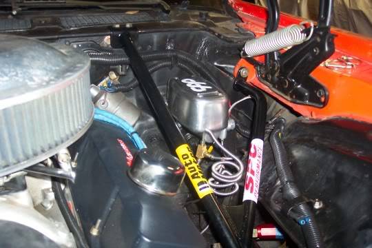
Like this, or do you need someting more substantial? Originally Posted by David Pozzi
 Scott from NJ.
Vent Windows Forever! ...
Feather-light suspension, Konis just couldn't hold
I'm so glad I took a look inside your showroom doors
10-09-2006 #24
Starting The Transformation
- Join Date
- Jun 2005
- Posts
- 379
What we did was support the car at all 4 suspension mounting points. We locked down 3 points and left the front drivers side float. We apply 10 PSI pressure (as read on the pnumatic lift's pressure gage) to the structure that supports the drivers side. This "pressure point" is actually 20" away from the frame rail. We then measure the amount of lift at a set point near the frame rail.
Bob
http://sn65.com/
10-09-2006 #25 Registered User
- Join Date
- May 2005
- Location
- Fontana, CA
- Posts
- 4,960
To add something to the Xbrace idea, Hotchkis makes this for convertibles. Wonder how well it would work in other applications. It seems to be in line with the ideas presented here.
http://www.hotchkis.net/cgi-bin/EDCs...catalogno=1404Nick R.
69 Camaro - 383, 700R4, 12 bolt 3.55, Hotchkis, Bilstein, Global West, Morris Classic
08 HHR SS - Still Stock for now
Do you still believe in all the things that you stood by before? Are you out there on the front lines, or at home keeping score?
Do you care to be the layer of the bricks that seal your fate? Would you rather be the architect of what we might create?
10-09-2006 #26 -Moderator-
- Join Date
- Apr 2001
- Location
- Central CA USA
- Posts
- 6,114
Bob,
Thanks for posting the links to your page. I really like your approach to the project.
BonzoHansen,
I'm familliar with those braces. I believe Herb Adams was the first to come up with them. The only thing I don't like about them is having to work around them. I'm wondering if there is a way to brace the sub without having tubes in the way of the engine. They also attach to the A arm bolt so you have them to deal with when aligning the car.David Pozzi http://www.pozziracing.com67 Camaro RS that will be faster than anything Mary owns.
10-09-2006 #27 -Moderator-
- Join Date
- Jul 2005
- Location
- Mountain View, CA
- Posts
- 9,583
Bob, Originally Posted by SN65
The stuff you've done looks nice, but all of the frontal changes leave a "dead path". Meaning they take the load from the strut tower and transmit them to the upper cowl, then the only path for that force is via the floor. It seems that distributing those loads from the cowl to both the SFC's and a cage via a-pillar bars would distribute the loads over a wider area and mitigate the bending force placed on the floor by the forces entering the upper portion of the cowl.True T.
Whats new with Project 1/2-Trak?
Follow my wisecracks on Sports, Food, Politics and other BS on Twitter.
My blog
When they kick out your front door, How you gonna come?
With your hands on your head, Or on the trigger of your gun?
10-09-2006 #28
Pro-Touring Veteran
- Join Date
- Aug 2004
- Location
- NY
- Posts
- 1,070
By adding all your reinforcement to the cowl forward and then the rear torq boxes back aren't you causing a soft spot in the center of the car. If you ever hit something the outer portions strength will crush the center section? Kind of the reverse of what most unibody mfg's due for safety?
I did a similar test on a 1st gen F body. I attached the front sub and measured movement as it was jacked from the front crossmember. The subframe connectors didn't really stop any flex from the cowl forward. Adding front cage struts just about eliminated all movement. Are you doing tests with front sheetmetal and doors attached? Just curious.
Weren't subframe connectors designned to strengthen the weak link in early unibody floors which lies between the front and rear rails. Some of the better designs have side to side ties.
10-09-2006 #29
-Moderator-
- Join Date
- Apr 2001
- Location
- Central CA USA
- Posts
- 6,114
For drag racing it makes a lot of sense to more directly couple the subframe to the leaf spring front mounts. I'd say it's good for any car with a lot of power but I did discuss it with Herb Adams once and he didn't think it was a important for handling on a coupe. He did recommend the front braces he designed.
Some of the fourth gen subframe connectors have diagonal bracing.David Pozzi http://www.pozziracing.com67 Camaro RS that will be faster than anything Mary owns.
10-10-2006 #30
Starting The Transformation
- Join Date
- Jun 2005
- Posts
- 379
Originally Posted by Damn True
Originally Posted by Damn True
Hi DT,
My plan was to transmit all forces to the cowl and then attempt to reinforce the cowl in such a manner that all the forces are then transmitted to the rockers.
If you look at the cowl bracing, it all originates from the major firewall reinforcement and then runs to the rockers and the "A" pillar. Instead of concentrating on sub frame connectors, we are attempting to transmit as much force as we can to the rockers.
So far, we have reduced deflection by 70%. Once we are finished with the basic modifications we will test the chassis one last time and then start on the cage.
Also, we are going with a 3 link rear. It will have two lower control arms, a torque tube and a watts link. All of the rear suspension forces will be carried by the coil over’s. We have modified the cage design to reinforce the shock mounting areas.
We have two goals here. First is to see just how much deflection we can take out of the chassis without the addition of a cage. Second, is to see just how much improvement we get with the addition of a cage.
If we can achieve a 75% to 80% reduction with just the chassis mods and the cage nets us an additional 10%, then we will consider the design a success. At that point, it becomes a matter of refining the design.Bob
http://sn65.com/
10-10-2006 #31
Starting The Transformation
- Join Date
- Jun 2005
- Posts
- 379
Originally Posted by BRIAN
Originally Posted by BRIAN
Hi Brian,
We have made quite a few changes to the floor structure. We have more than doubled the strength of the rockers and also the center of the floor with the addition of modified convertible items.
Yes the center section is the weakest area of the car but, other than adding a cage (which we plan on doing) there really is not much we can do. If you have any ideas, I am open to suggestions.
Weren't subframe connectors designed to strengthen the weak link in early unibody floors which lies between the front and rear rails. Some of the better designs have side to side ties.
Bob
http://sn65.com/
10-10-2006 #32
Starting The Transformation
- Join Date
- Jun 2005
- Posts
- 379
Hi David, Originally Posted by David Pozzi
We are going to see a lot of force at the front leaf spring mount (now a lower control arm mount) but those forces are going to be more horizontal than verticle. We are just going to beef up the mounting point a bit and allow the rockers to take most of the force. In addition to that, we will be locating one of the legs of the cage right on top of this area.Bob
http://sn65.com/
10-10-2006 #33 Registered User
- Join Date
- Nov 2002
- Location
- state of confusion
- Posts
- 1,499
The closer that you can get the LCA axes to align with the rocker axes the less the bracket compliance will be, and the smaller the bending moments applied at the ends of the rocker structure will be . . .
Norm'08 GT coupe, 5M, suspension unstockish (the occasional track toy)
'19 WRX, Turbo-H4/6M (the family sedan . . . seriously)
Gone but not forgotten dep't:
'01 Maxima 20AE 5M, '10 LGT 6M, '95 626, V6/5M; '79 Malibu, V8/4M-5M; '87 Maxima, V6/5M; '72 Pinto, I4/4M; '64 Dodge V8/3A
10-10-2006 #34 Registered User
- Join Date
- Sep 2001
- Location
- Accord, NY
- Posts
- 2,295
Are those Herb Adams? I have a set to install and have some questions. Thanks.
Originally Posted by BonzoHansen
69 Camaro convertible, 410, M22, 8-pt cage therapy program. SOLD.
68 camaro - SOLD
67 Bel Air - New street project with perfect floors, frame and trunk!
10-10-2006 #35
Starting The Transformation
- Join Date
- Jun 2005
- Posts
- 379
Exactly, we have the LCA meeting the chassis near the bottom of the rocker and just under the bottom of the axle. I think the LCA will be close to horizontal, but will likely run uphill a bit from the axle to the chassis. Won't know for sure till we set the car at ride height, possition the axle and fit up the control arms. Originally Posted by Norm Peterson
Bob
http://sn65.com/
10-10-2006 #36 Registered User
- Join Date
- Mar 2004
- Location
- Mid-Michigan
- Posts
- 2,764
Just an observation on my part.
You have, essentially, made your outer rockers into subframe connectors. Tying everything together as you have does "just about" the same job that a set of connectors would do other then directing the stress path into a circuitous, round about, route through the rockers. As much work as you have done to beef them up could probably have been accomplished by a simple tube tying the front cradle directly rearward into the front leaf pocket. I am not saying this won't work as it will probably be fine. The point to be made is that, in getting around installing "subframe connectors", you have actually installed "subframe connectors"... Whether you realized it or not...
Just me thinking out loud... Anybody else?
MarkMark:
"Bad Ast" Astro Van. Just because I did it... Doesn't mean it's possible...
This my Bad Ast thread...
https://www.pro-touring.com/showthre...roject-Faze-II
This is my Fotki album...
http://astroracer.fotki.com/
10-10-2006 #37
Starting The Transformation
- Join Date
- Jun 2005
- Posts
- 379
Hi Mark, Originally Posted by astroracer
You know... This is the way I originally thought. But I came to the realization that you have to look at the entire structure when it comes to a unibody.
I look at the chassis as a whole with the center body section as the major unibody structure. The roof, "A" & "B" pillars, firewall, cowl and rockers form the major structure of the chassis. The frame rails need to tie back to this structure.
If you look at the rockers, especially in our case, they are the heaviest structural item in the entire car, and the basis of all other assemblies. Even if you added a sub-frame connector that was as structurally sound as our rockers (about a 6"x6" section), I doubt that that assembly would be as stable as ours. You would not be taking advantage of the rest of the structure. And, you would still need to tie this sub frame structure to the rest of the chassis through more than the floor pan.Bob
http://sn65.com/
10-10-2006 #38
Registered User
- Join Date
- Mar 2004
- Location
- Mid-Michigan
- Posts
- 2,764
Hey Bob, you are exactly right of course, which is why "most" subframe connectors are tied into the roll cage at a couple of points.
Don't take me wrong here. I am not arguing your method. I think it will work just fine. In your initial post you asked "what do subframe connectors do?" All I am doing is making the point that a simple connector would probably do the same job you are drafting the rockers to do. Of course the connectors would HAVE to be tied into your structure as you mentioned and would probably require just as much work as rebuilding the rockers to make them work as hard.
MarkMark:
"Bad Ast" Astro Van. Just because I did it... Doesn't mean it's possible...
This my Bad Ast thread...
https://www.pro-touring.com/showthre...roject-Faze-II
This is my Fotki album...
http://astroracer.fotki.com/
10-10-2006 #39
-Moderator-
- Join Date
- Jul 2005
- Location
- Mountain View, CA
- Posts
- 9,583
Let's take a second to draw a distinction between a subframe connector that bolts to the front and rear and one that welds into the front and rear AND is welded into the floorpan between the two.
Bob's setup clearly emulates the latter and should by far exceed the former.True T.
Whats new with Project 1/2-Trak?
Follow my wisecracks on Sports, Food, Politics and other BS on Twitter.
My blog
When they kick out your front door, How you gonna come?
With your hands on your head, Or on the trigger of your gun?
10-10-2006 #40 Registered User
- Join Date
- Nov 2005
- Location
- Mesa, AZ
- Posts
- 133
I have been dying to try out that structural foam in the A pillars and roof structure for a while now. I will be interested to see how easy it is to work with and the results.
I have also been toying with building a similar style of brace as your front shock tower brace except as a backbone on the center console. What I mean is leave the original sheetmetal there, and weld a tubular structure onto it to form a backbone from the firewall area to the backseat area. Have you considered this? I believe this will cut down on torsional deflection without intruding into the passenger compartment like a cage would. I would be interested to see how this would work.
I like the idea of the beefed up rocker panels for various reasons, the first being crash safety. A subframe connector does nothing to help you in the case of a side impact, but a beefed up rocker panel could very well minimize intrusion. It also as you have stated, ties into the structure of the body which is nice. It might be beneficial to beef the rockers up AND install subframe connectors in a car like a camaro or firebird where there is a subframe that bolts to the middle of a flat panel. Keep thinking outside the box!-Dennis
56 DMAX GMC
http://www.cardomain.com/ride/2135587
1968 Firebird
http://www.cardomain.com/ride/2135556
1966 Suburban
http://www.cardomain.com/ride/2135589

 Reply With Quote


